
Can I make an automatic card dealer? (PCB Part #2) #
Group Assignment #
For our group assignment, we learned how to manufacture the boards that we designed in the previous week, using MODS, which is a program that takes png of our board outlines and makes gcode for the Carvera, which is the PCB milling cnc we are using this week.
Individual Assignment #
Now that I have my designed PCB board, it is time to mill and solder!
I used the Carvera desktop cnc mill and a copper and FR1 composite to make my board. I used Quentin’s handy gerber to png converter to get the png files for my traces and board outline.
Board outline png: #

Trace png: #
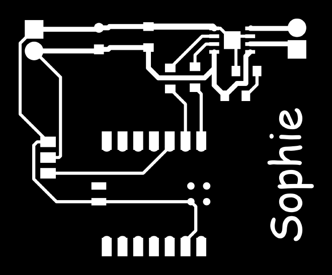
Next, I uploaded the pngs to the mods website and downloaded my gcode files for milling!

Here is my final gcode file! I folled Quentin’s helpful Carvera documentation for the milling process.
Milling in Action #
I used a 6 mm offset in both the x and y directions to mill my board on the copper and FR1 composite. I made sure to check the outlines and see that nothing intersected with the clamps or would cut out of the boundary. I uploaded it to the machine to mill and it came out quite nice!

Finishing Touches #
I gathered my components that I designed into the footprints: the 100 uF capacitor, the two 0.1 uF capacitors, the 0 Ohm jumper resistors, the motor driver, the power input and outputs, the terminals, and my microcontroller, the Xiao rp2040. I started soldering. I used tin solder and a bit of flux on all of the pads to help with flow. The soldering process was pretty smooth overall, but I had a short on one of the traces for the motor driver. I was able to fix it with some solder wick and a sharp razor blade.


I connected a DC motor to the pcb and used a 5V power supply with a 0.4 current limit to test. (I couldn’t find a servo but when I do I will test it very soon!)

The system integration definitely needs some work, but this is just for testing for now. The H bridge in the motor controller works great, and changing the PWM signals allows me to drive the motor forward and reverse! Using the scope to inspect, we can see that the sign of the voltages does change when we switch the values for IN1 and IN2 in the code!


I used micropython to write a simple script to run the motor in different directions at two second intervals.
Reflections #
- I realized I should have put the rp2040 on the edge of the board so the USBC connector dangles off and connects more easily. Oops!
- I should have changed the big capacitor to smd instead of through hole because I realized the Carvera did not include drilling on the toolpath. I was able to solder the smd one directy onto the footprint fine though, and the capacitance did read through on the scope through the time delay seen on the voltage!
- Flux is very helpful, but you do not need to use that much solder! I was a little gratuitous with my solder usage initially which caused some overflowing and shorts.