week 5
electronics design
designing a PCB
The assignment for this week was to use an EDA (electronic design automation) tool to design a development board to interact and communicate with an embedded microcontroller.
I have very little experience in electronics and this was my first time designing a PCB, but I was looking forward to this week as it has a lot of application to my final project.
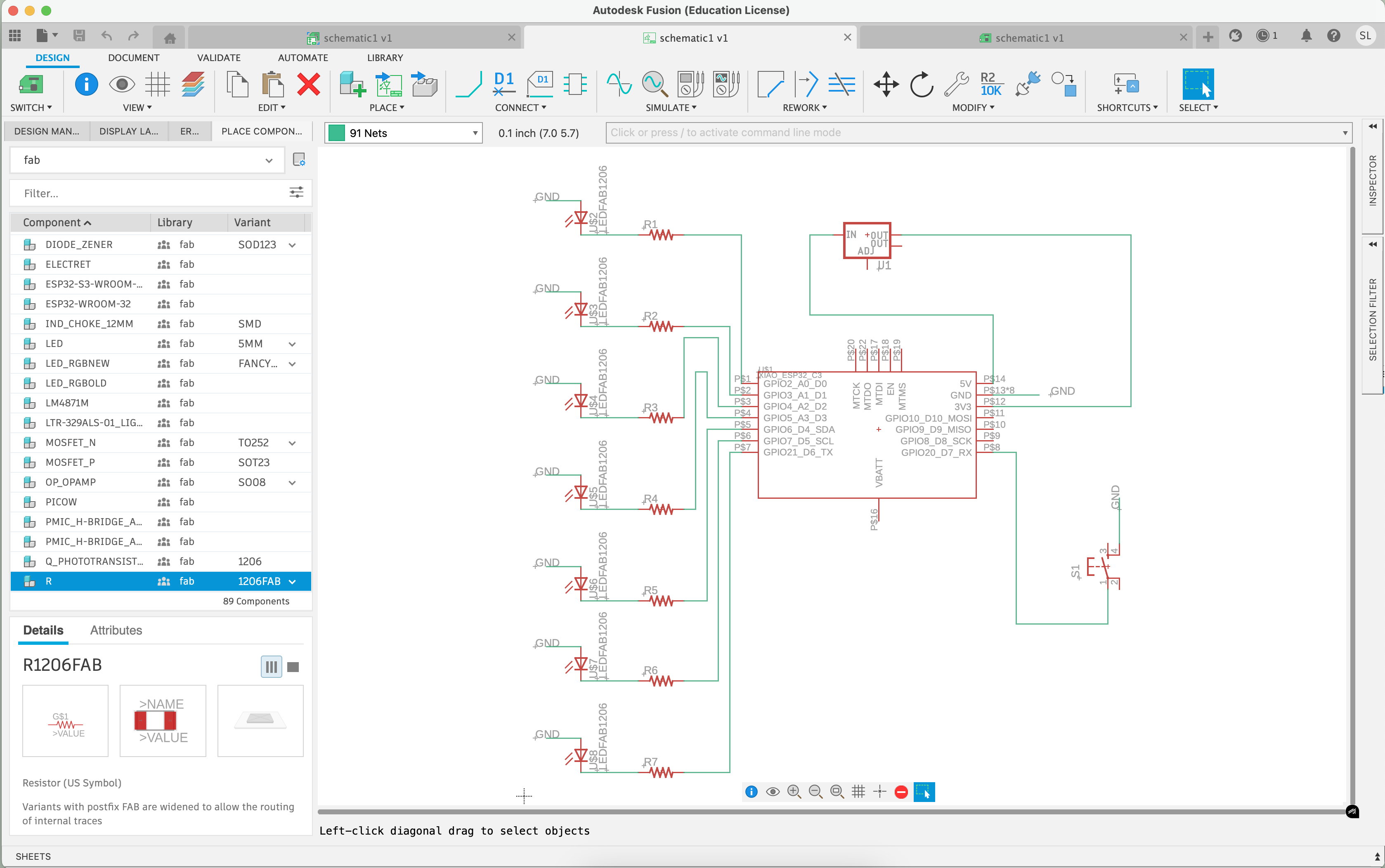
I decided to use Fusion to design my board. like week 3, I decided to stick with the XIAO ESP32C3 for its WiFi capabilities (also because I am somewhat familiar with this particular microcontroller and its pin setup now), which will be important in the coming weeks. For this project, I wanted to design a PCB involving LEDs. I relied on the inital knowledge from the Wokwi simulation in week 3, where I learned about things like connecting the LEDs to resistors, and the LEDs to GND, and GND to the button, etc. I first very crudely drafted a schematic of this:
Our TA Yuval very kindly pointed out that I was missing a resistor, so I added one:
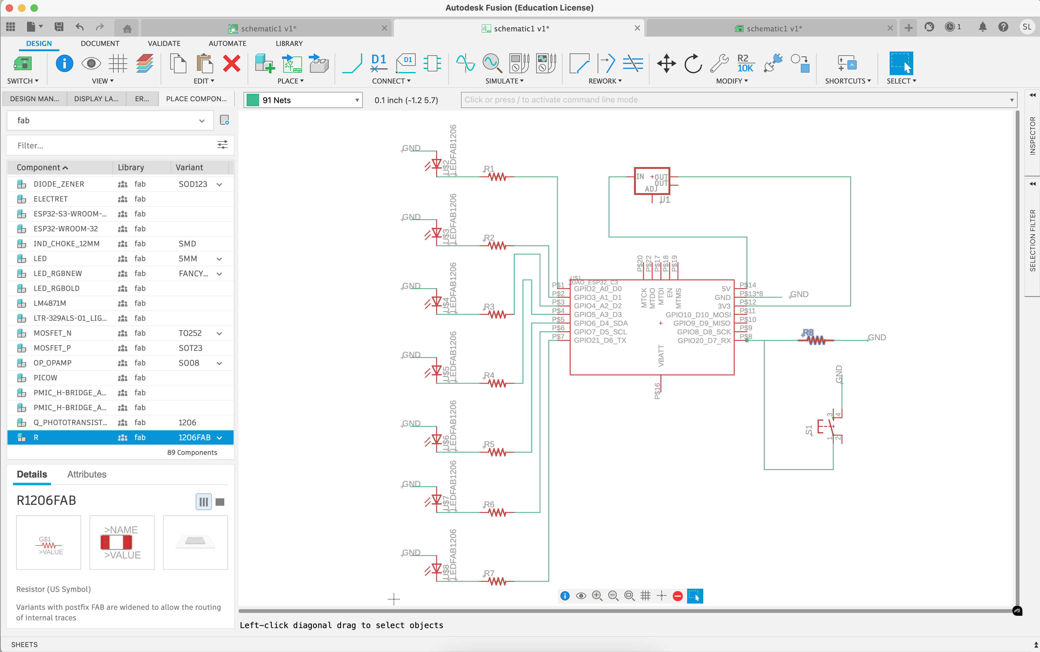
I decided to add 7 LEDs and a button for my PCB. I'll program it next week, but the idea is that once the button is pressed, the LEDs light up in some sort of pattern and the lights can do a little dance.
The schematic generally looked OK, so I went ahead and switched the views
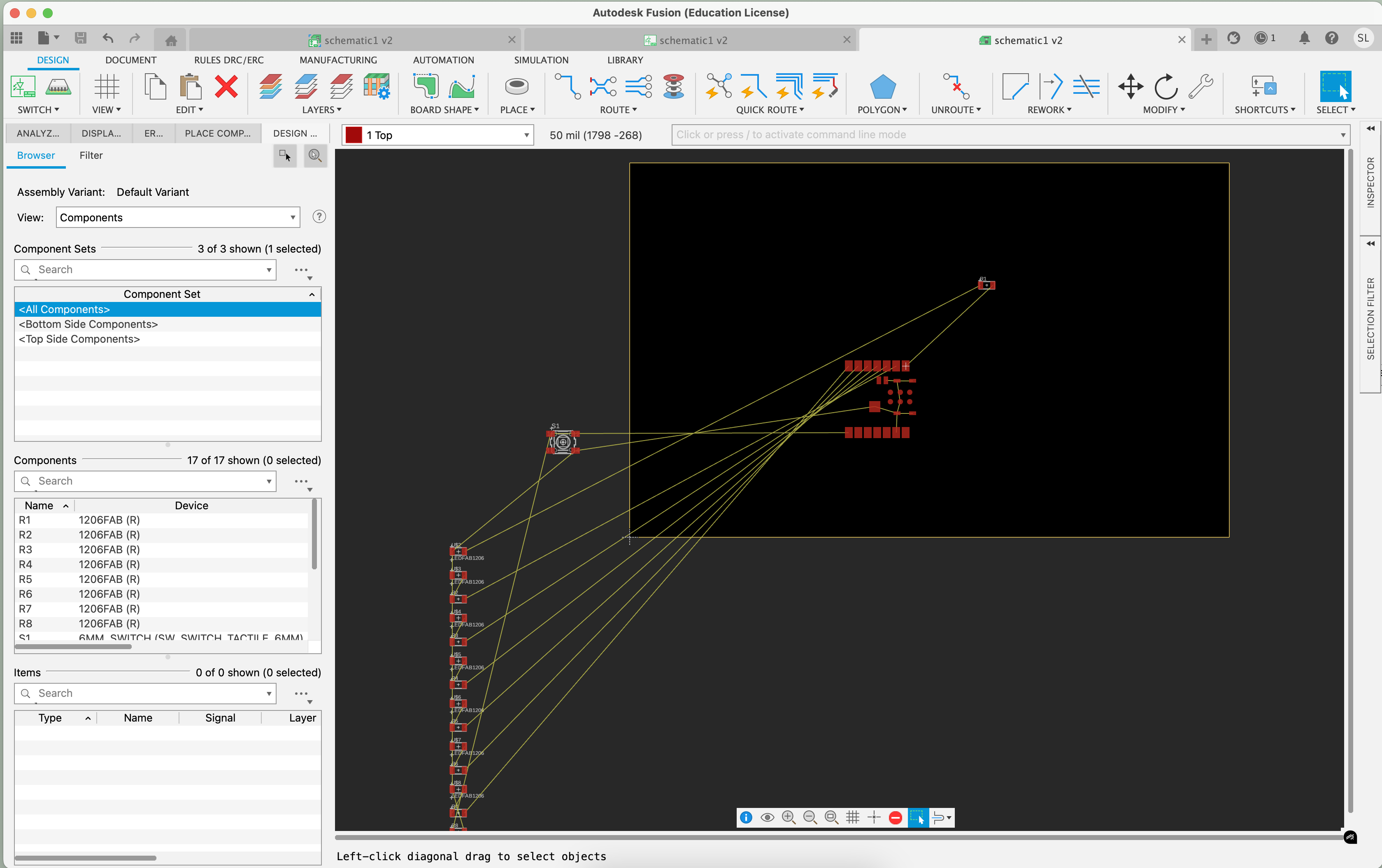
It didn't look great. I was wondering what happened, but Yuval assured me that it was fine and I could adjust the view by dragging and designing the different elements. I understood that the schematic just outlines the overall and logic and the relationship between the different components to each other, but I thought it would transfer over slightly better to the design by default
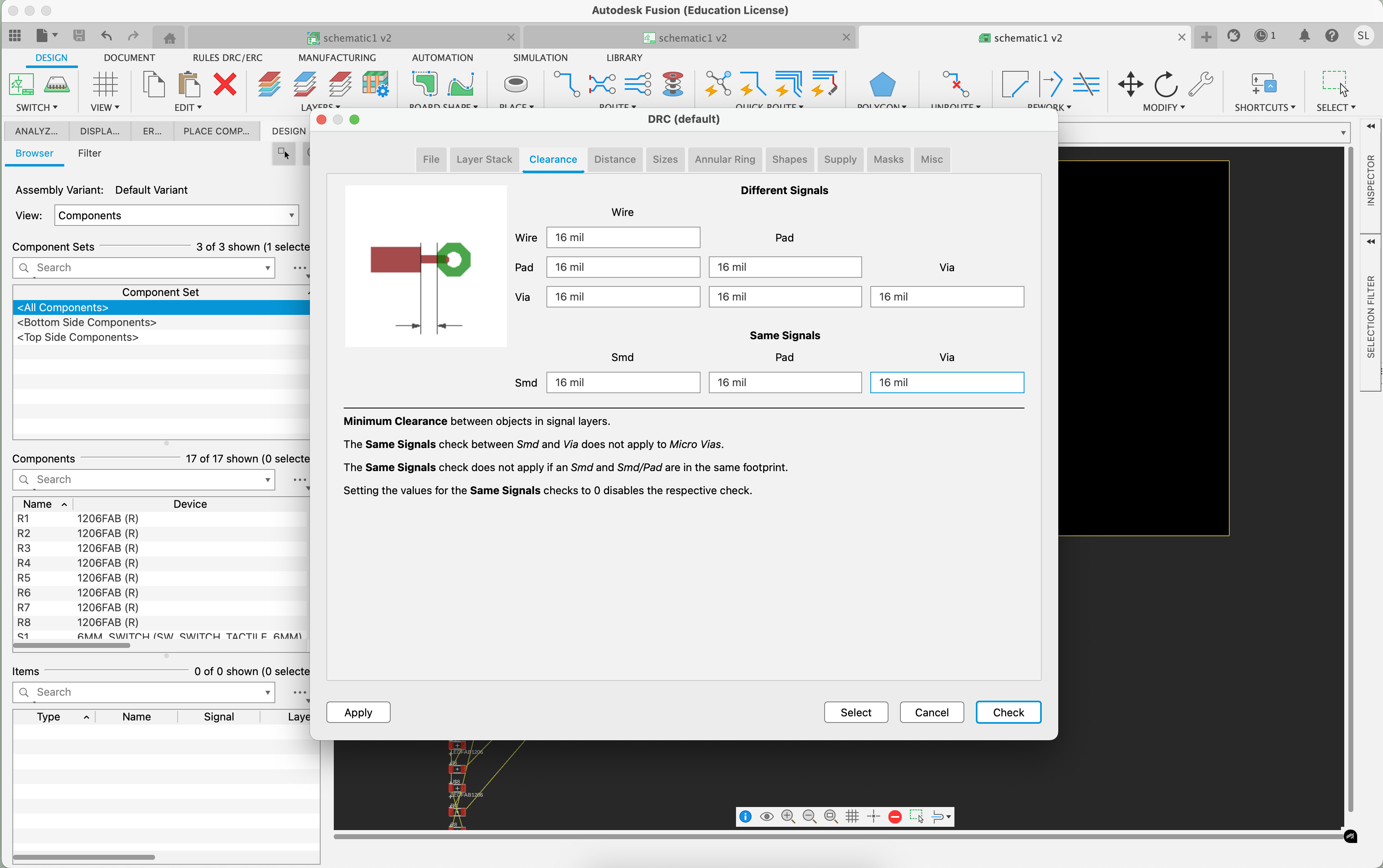
In this step, I made sure to adjust the DRCs, which will be important when we actually mill the PCB next week.
Next, I started moving the different components around on the board, being cognizant of how this would look like on an actual milled board.
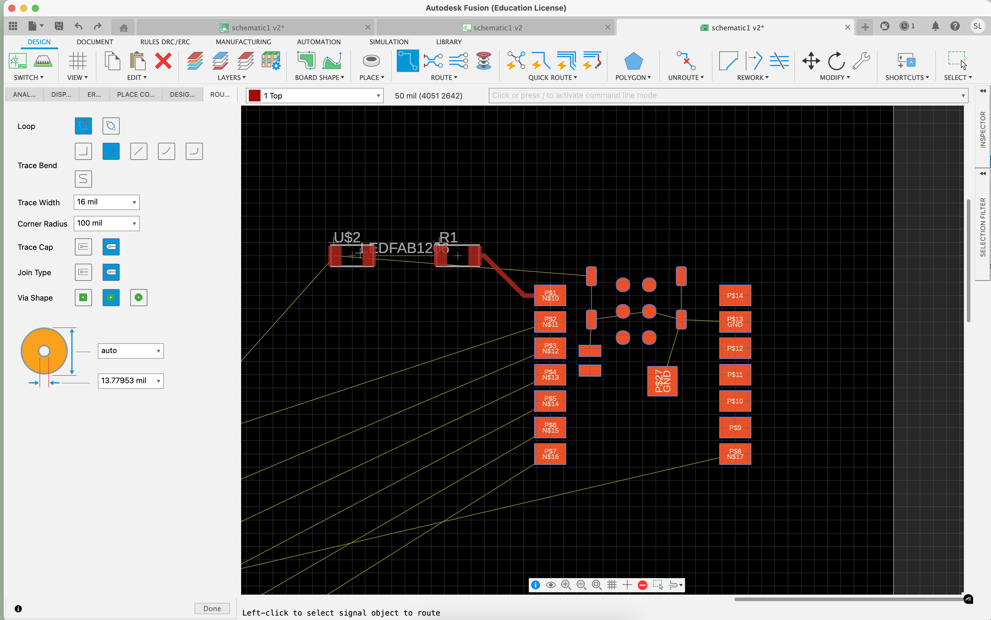
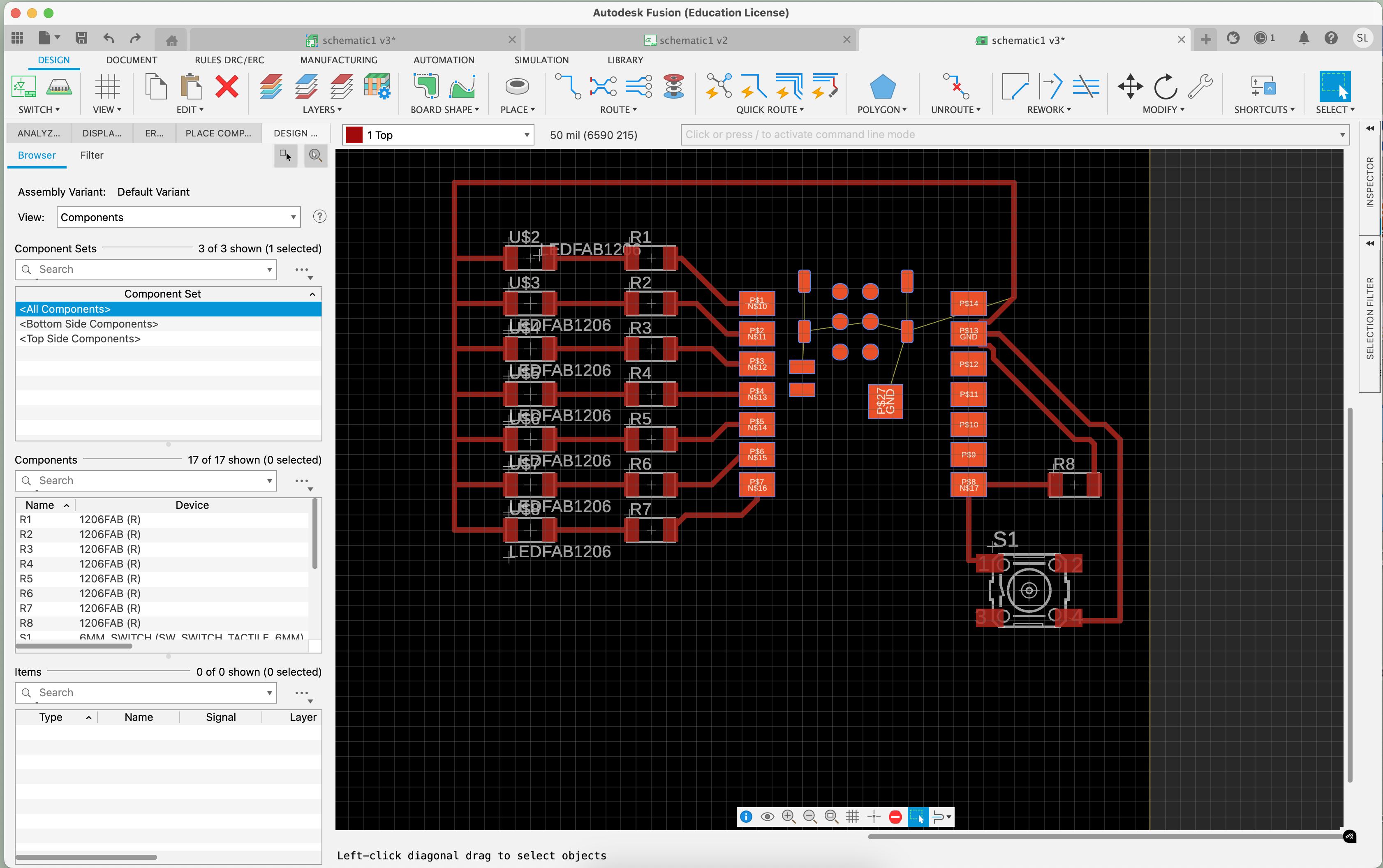
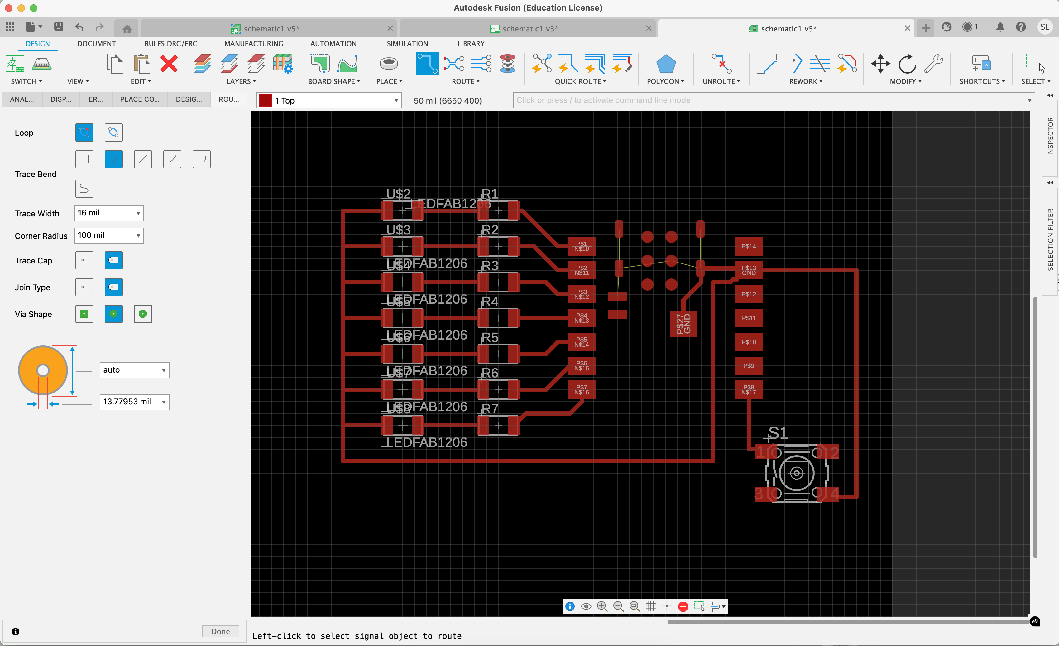
A better looking PCB design in progress:
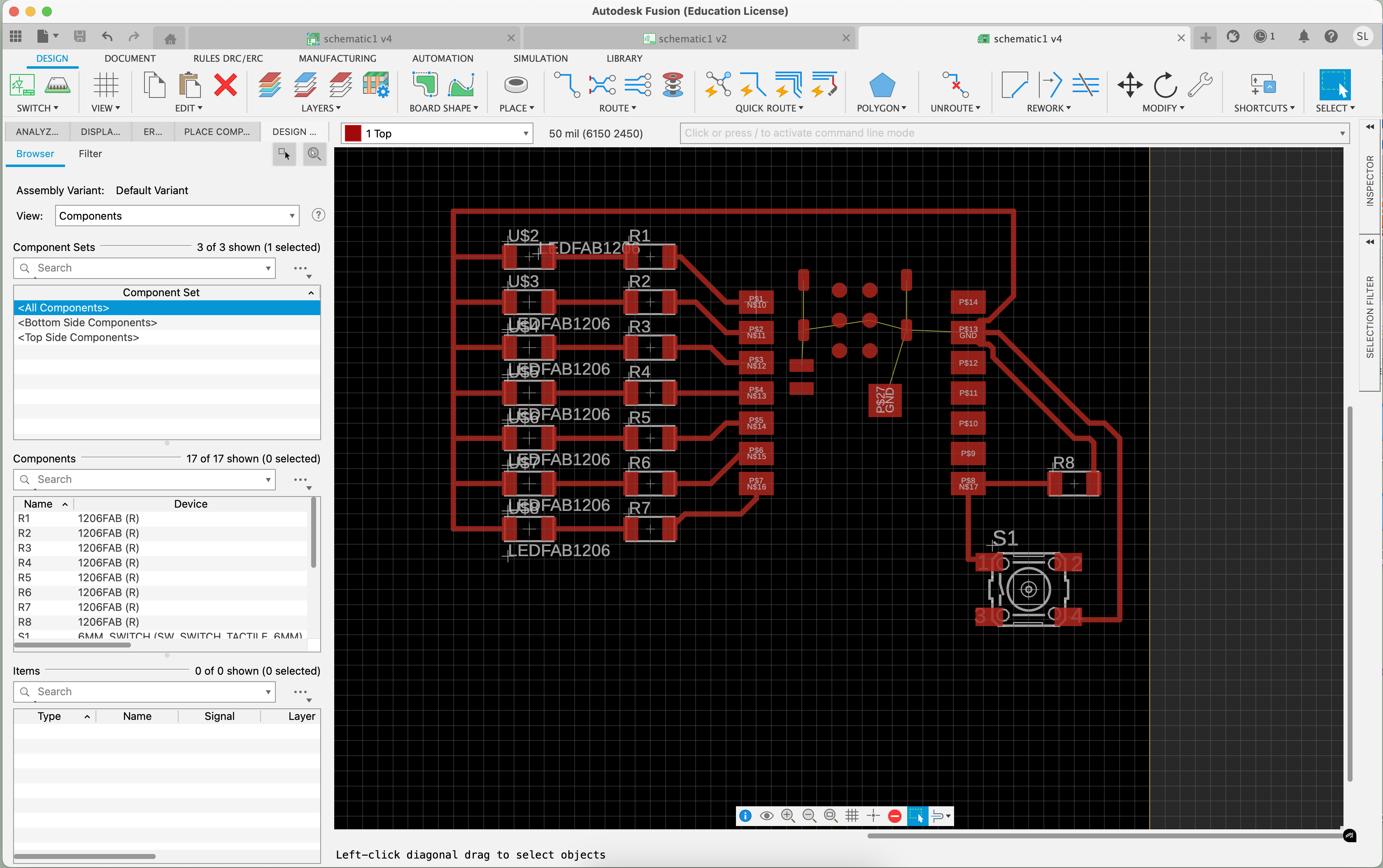
Midway, Anthony gave me some feedback and said the ground connector going around the top may cause problems next week, so I decided to move it underneath the ESP32 and connect the components that way instead. He also mentioned that I could get rid of R8 on the right side and not lose any capabilities, so I got rid of it for now:
