week 6
electronics production
making a microcontroller development board
The individual assignment for this week was to make and test a microcontroller development board that I designed. I decided to use the PCB that I designed last week.
However, I decided to change the design of my board so I could make a miniature version of my final project... this is where things went wrong and led me to lose several hours (and I ended up pivoting in the end. Such is life). The PCB design I made last week was fairly simple: it featured an ESP32, 7 LEDs, and a switch button. I had originally planned to program it so that when the switch is pressed, the LEDs light up in some sort of predetermined pattern.
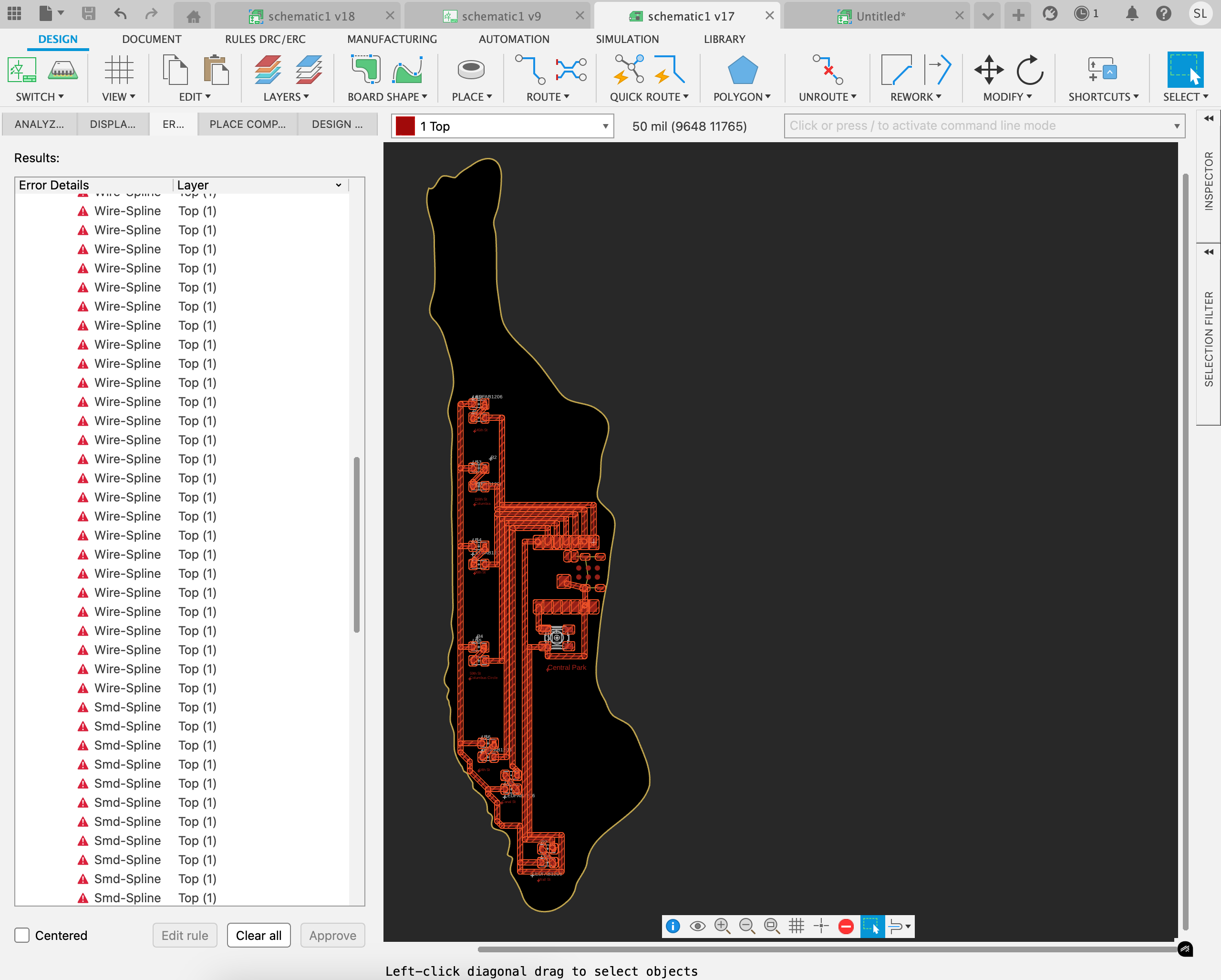
I wanted to keep things fairly simple as I'd be traveling for a good chunk of this week and thus would be away from lab, but I decided I wanted to make it a little more interesting, so I reconfigured my design so that it would look like a silhouette of Manhattan. I positioned each of the 7 LED-resistor pairs on the 123 subway line (I chose the locations of 7 different stations on this particular line, which runs northeast to the southern tip of the city) so that each "station" would light up when the subway arrives. I planned to fetch the arrival data from the MTA API. I figured this would also be useful for my final project.
Well, I figured adjusting the design would be pretty simple but it actually ended up causing a lot of problems. Clearly I'm still bad at using Fusion. Thanks to Yuval and Anthony, we sort of (?) figured it out (we decided to ignore the 240 error flags that popped up), but then milling issues ensued.
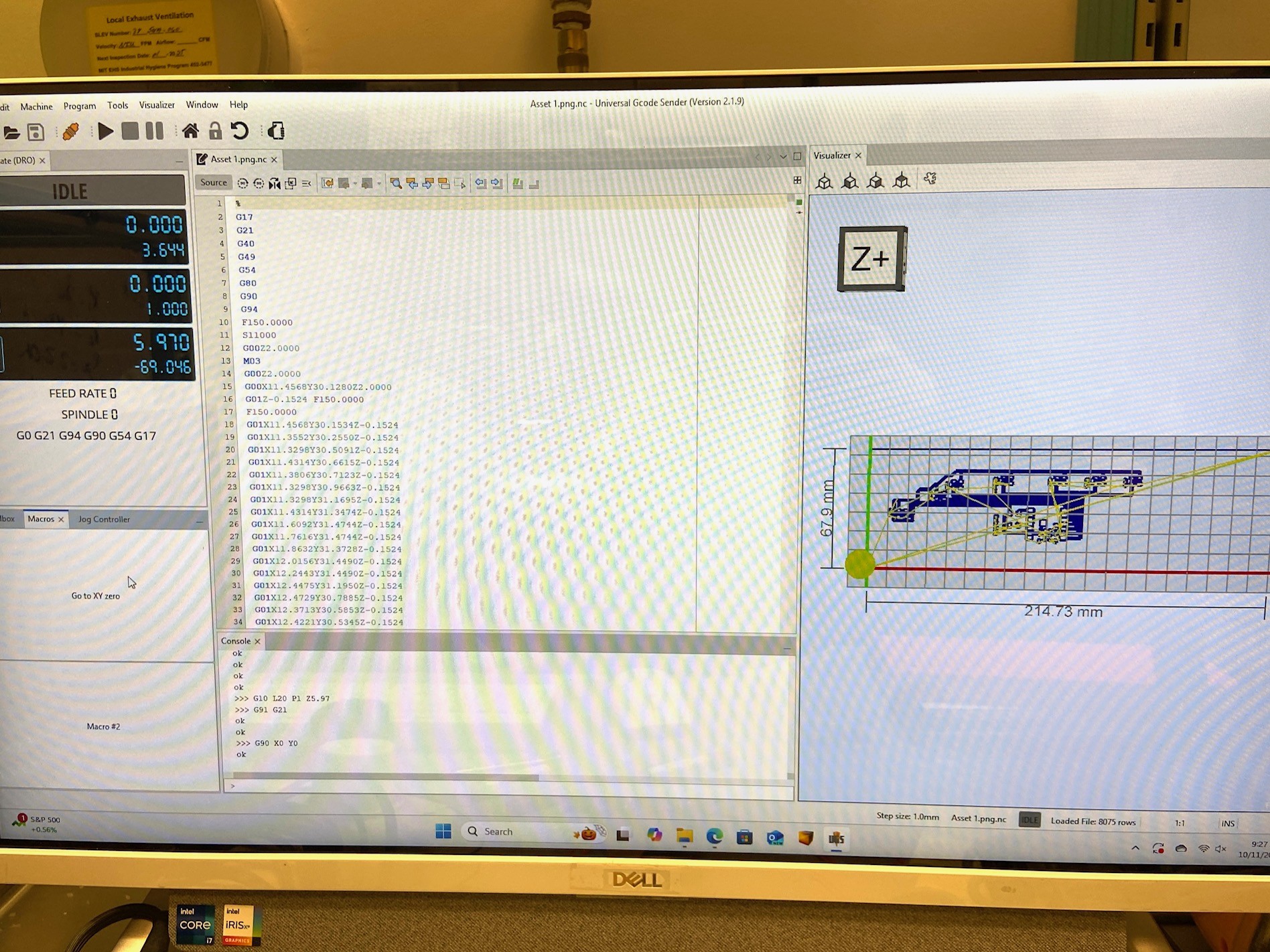
I had to use the bigger "less friendly" milling machine as my design was a bit bigger at 7 inches.
Setting up the board
Milling the board
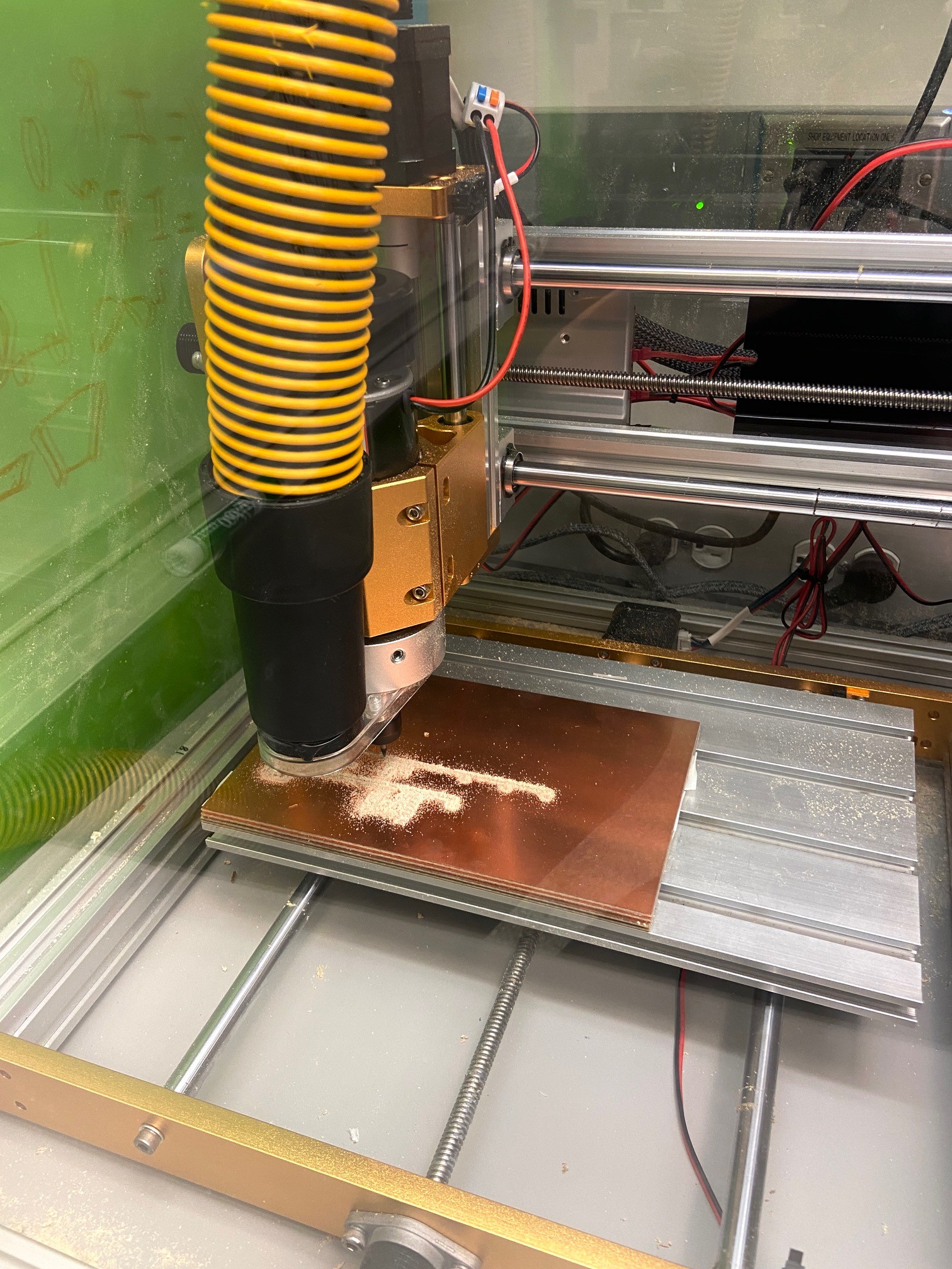
This machine took much longer than the other one (Bantam Tools desktop PCB milling machine) we had in lab. I returned after an hour to pick up the completed, milled PCB, only to see that it had failed:
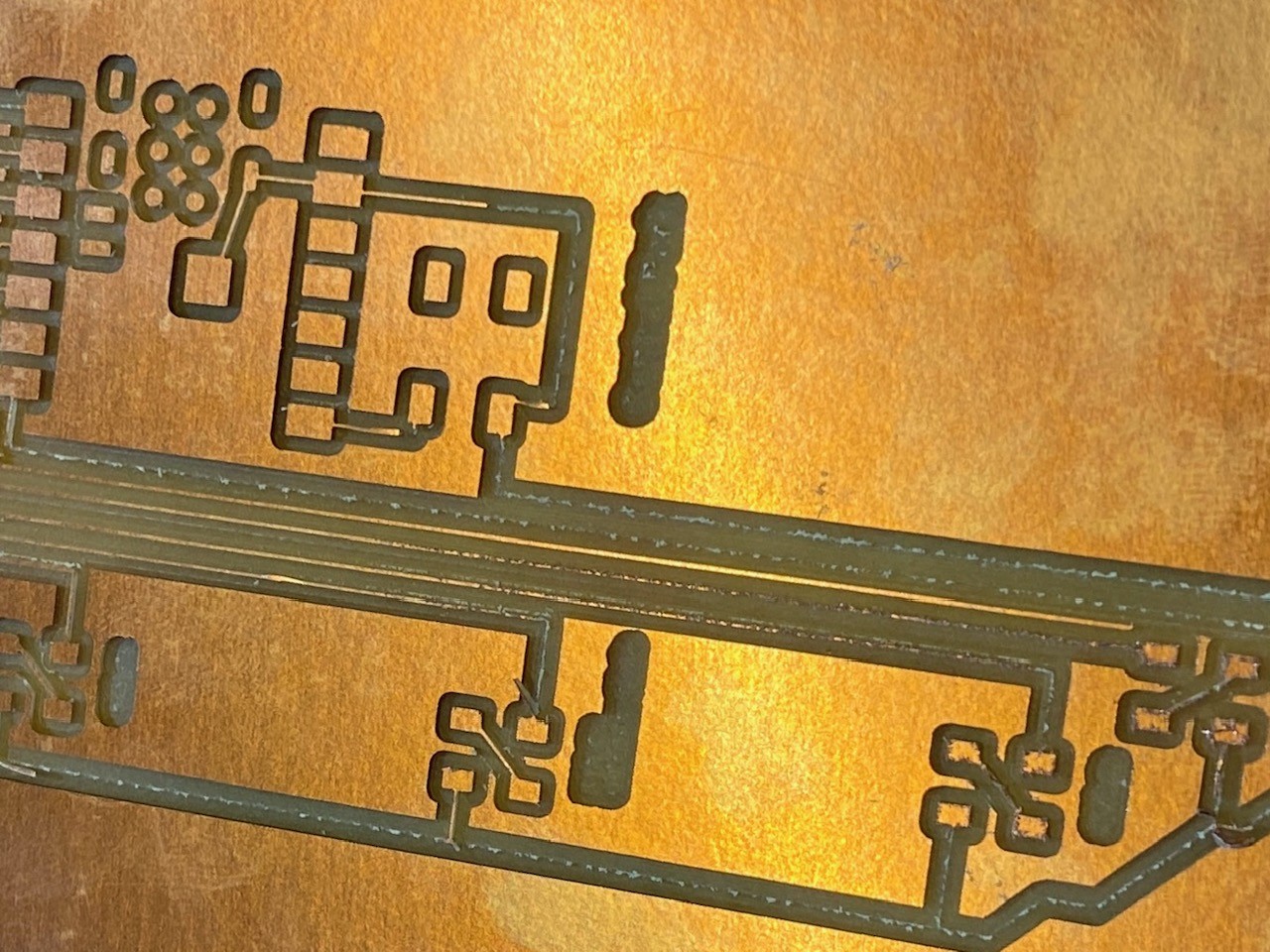
What happened?
I re-checked all of my design rules and consulted Anthony, but the design was compliant and neither of us could detect any issues.
I reverted to my original design for the time being due to time constraints, and was able to use the Bantam Tools desktop PCB milling machine as this one was a much smaller board. I used the 1/64'' and 1/32'' flat end mills. The milling process was pretty straightforward -- thankfully, there were no milling problems this round (thanks to Emma for her help in setting up the machine).
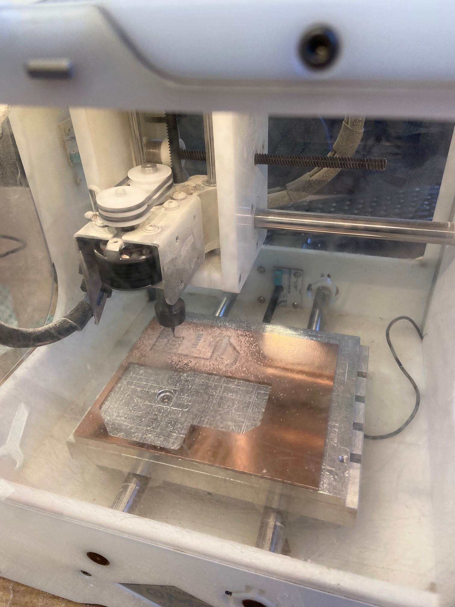
My milled PCB, pre-cleaning. The edges were a bit rough, but it quickly smoothed out after taking some sandpaper to it.
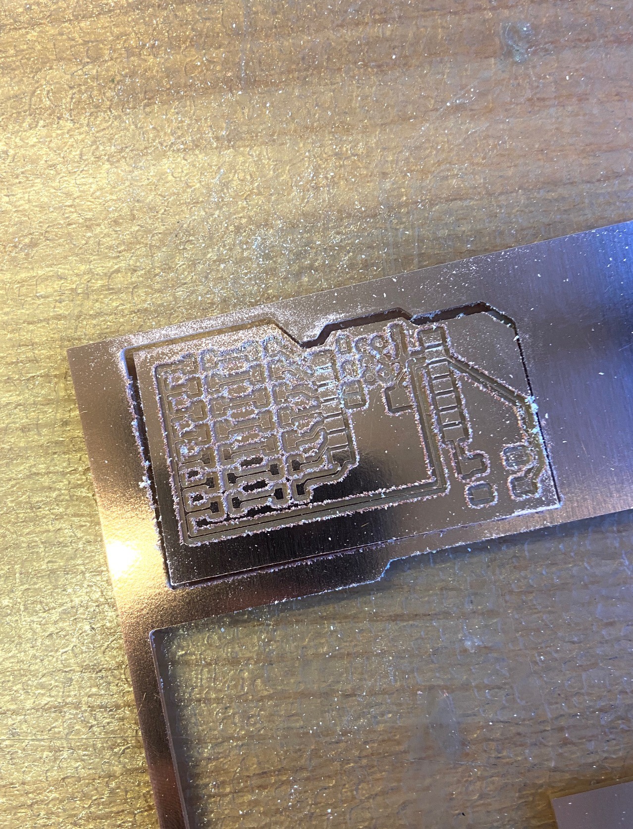
Soldering my PCB. This was my first time soldering! It's a skill that I've always wanted to learn. I started off with the switch (the lab ran out of the square switches, which is what's on my board / what I designed with, but this shape worked fine, albeit looking a little funky). The soldering process went pretty smoothly, though it took longer than expected. I thought I'd toasted some of my LEDs, but they ended up working just fine -- I checked the connections using a multimeter to ensure everything was working correctly, and proceeded to solder the rest of the board after confirming. While everything worked fine, the soldered joints just looked... ok-ish. I'd definitely like to become more efficient and precise at soldering.
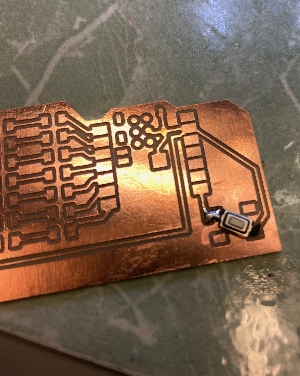
My completed PCB, all parts soldered


I realized that I chose red, white, and green LED colors, so I decided to program the LEDs to light up in the pattern of the main chorus of "Jingle Bells." This was done in Arduino IDE, and ChatGPT was used to debug.
    // Define the pins for the LEDs and button
    const int ledPins[] = {2, 4, 5, 12, 13, 14, 15}; // Pins on the left side of ESP32
    const int buttonPin = 0; // Pin for the button
    int buttonState = 0;

    // Define timing for the song rhythm (in milliseconds)
    const int shortNote = 300;   // Short note duration
    const int longNote = 600;    // Long note duration
    const int pauseBetween = 100; // Short pause between notes

    // Colors: red, white, green, white, red, white, green (from ledPins array)

    // Map the lyrics to the LED colors
    void playJingleBells() {
      // "Jingle bells, jingle bells" (Both Red LEDs light up for "Jingle bells")
      for (int i = 0; i < 2; i++) {
        // Jingle (both red LEDs)
        digitalWrite(ledPins[0], HIGH); // Red LED 1
        digitalWrite(ledPins[4], HIGH); // Red LED 2
        delay(shortNote);
        digitalWrite(ledPins[0], LOW);  // Turn off Red LED 1
        digitalWrite(ledPins[4], LOW);  // Turn off Red LED 2
        delay(pauseBetween);

        // Bells (White and Green for "bells")
        digitalWrite(ledPins[1], HIGH); delay(shortNote); digitalWrite(ledPins[1], LOW); delay(pauseBetween); // White LED
        digitalWrite(ledPins[2], HIGH); delay(longNote);  digitalWrite(ledPins[2], LOW); delay(pauseBetween); // Green LED
      }

      // "Jingle all the way" (White, Red, White)
      digitalWrite(ledPins[3], HIGH); delay(shortNote); digitalWrite(ledPins[3], LOW); delay(pauseBetween); // White LED
      digitalWrite(ledPins[4], HIGH); delay(shortNote); digitalWrite(ledPins[4], LOW); delay(pauseBetween); // Red LED
      digitalWrite(ledPins[5], HIGH); delay(longNote);  digitalWrite(ledPins[5], LOW); delay(pauseBetween); // White LED

      // Short pause between phrases
      delay(500);

    void setup() {
        for (int i = 0; i < 7; i++) {
            pinMode(ledPins[i], OUTPUT);
        }
        pinMode(buttonPin, INPUT);
    }

    void loop() {
      // Read the state of the button
      buttonState = digitalRead(buttonPin);

      if (buttonState == HIGH) {
        // Play the "Jingle Bells" LED pattern when the button is pressed
        playJingleBells();
      }
    }
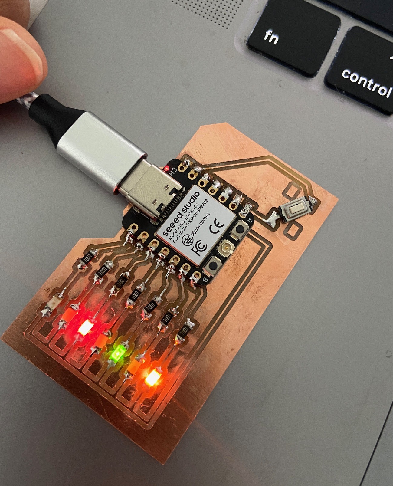
Many thanks to Anthony for his seemingly unending patience! As a next step, look into LED multiplexing as I work with more complicated and higher volume LED configurations. Once I figure out LED multiplexing for my final project, I plan to design and make that board as soon as possible. I'm wondering how I'll be able to solder nearly 500 LEDs...