week 8
input devices
This week's assignment is to measure and read something by adding a sensor to a microcontroller board that I've designed.
I saw that next week we will be doing output devices. After scrolling through what would be covered in both input and output weeks, I figured that it would make more sense to combine these two weeks to make a PCB that would handle both input and output.
To start, I looked through the different types of inputs and outputs that we could experiment with, and I also parsed through Neil's example boards as inspiration. Input devices and sensors actually aren't too relevant for my final project, so I decided that I would just do something I found interesting.
I decided to design a microcontroller board that senses light (input) and then prints out a message on an LCD screen depending on light levels (output). Since I am working with an ESP32 again, I might also play around with its WiFi capabilities and the OLED.
I first decided the schematic for my microcontroller board. I drew inspiration from Neil's hello.light.45 and hello.SSD1306.RP2040 boards, though I made some significant modifications as I was combining both into one board, added a switch, and was using a different type of microcontroller. I also decided to try designing in KiCad instead of Fusion this time: every time I open Fusion, my laptop overheats and the software crashes... and I like that KiCad is open source.
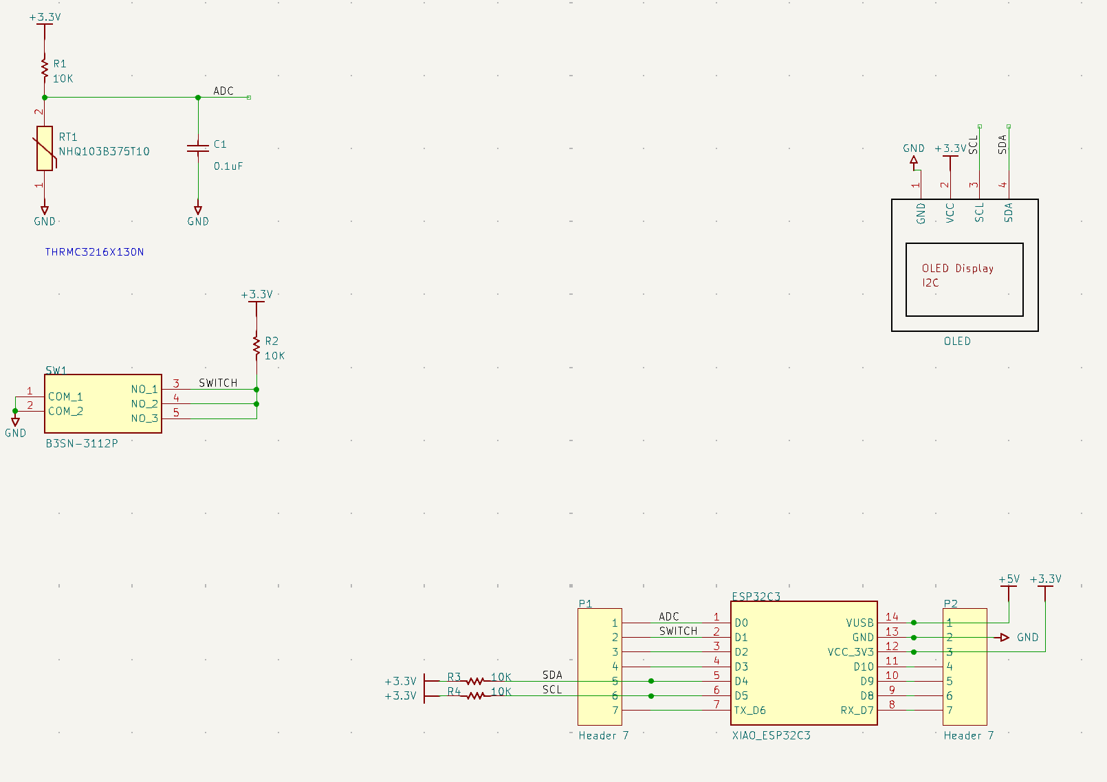
In terms of components, I used a XIAO ESP32C3, a phototransistor, a capacitor, 2 headers, a switch, various resistors (pull-up resistors and a voltage resistor), and an OLED screen.
Here is the schematic:
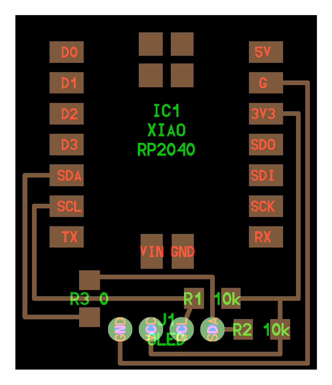
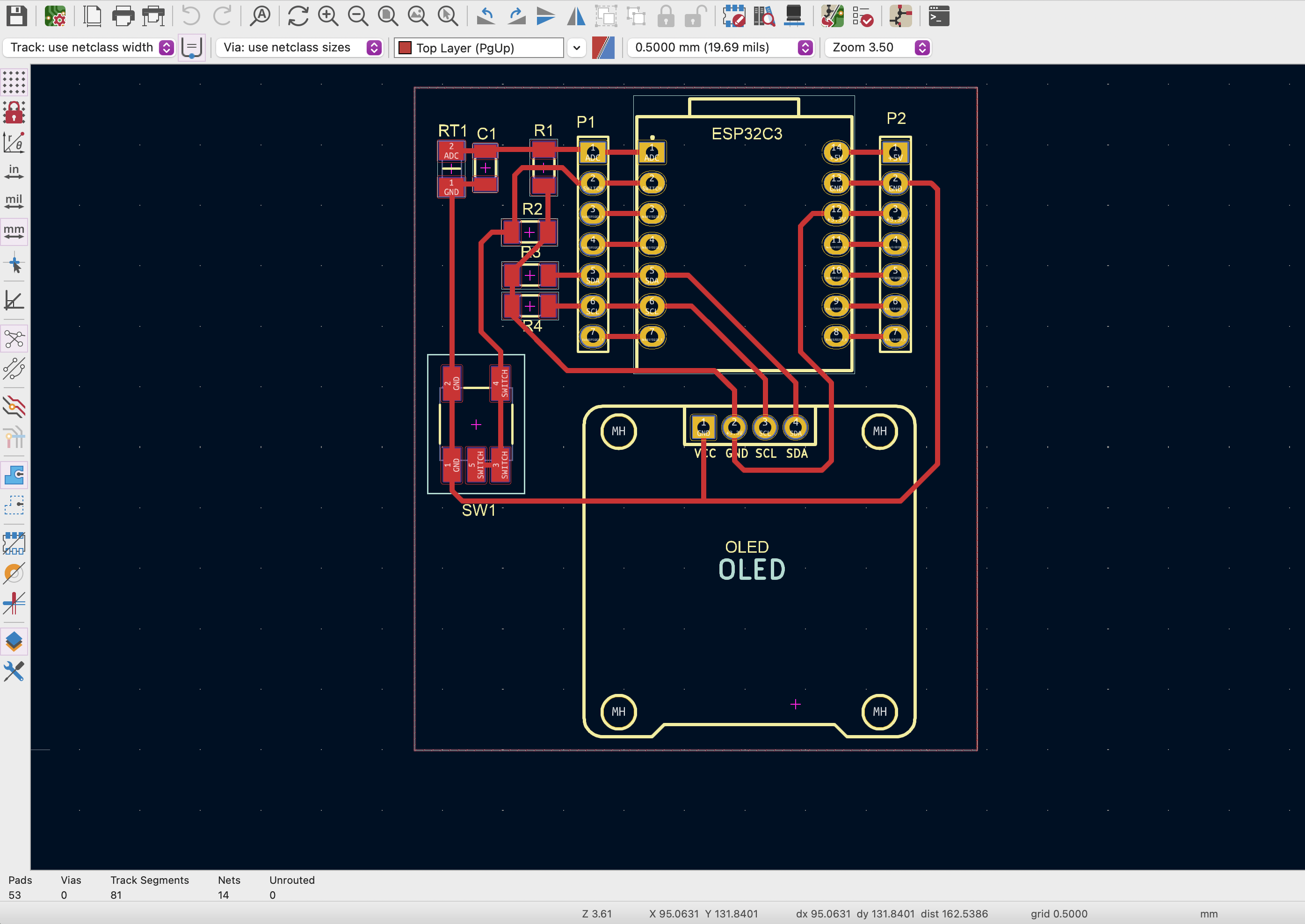
Here is the corresponding design:
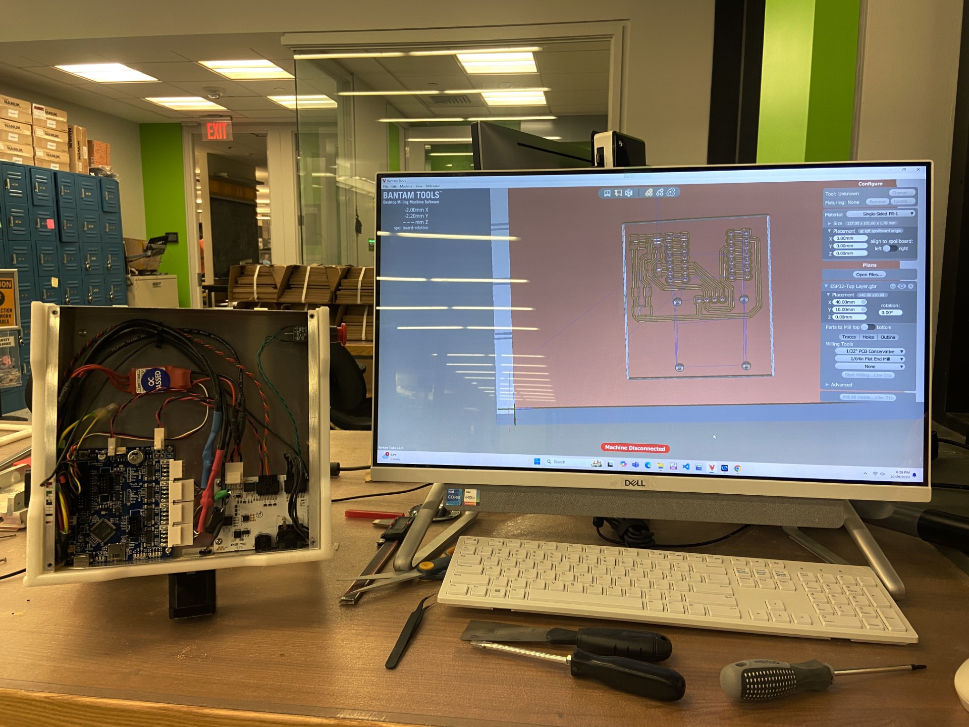
After designing, I then milled my board using the Bantam mill in the EECS lab. This was quite a process, because the Bantam actually broke while I was setting the Z height and was out of commission for a couple of hours (see below). Eventually, Anthony figured out a workaround!
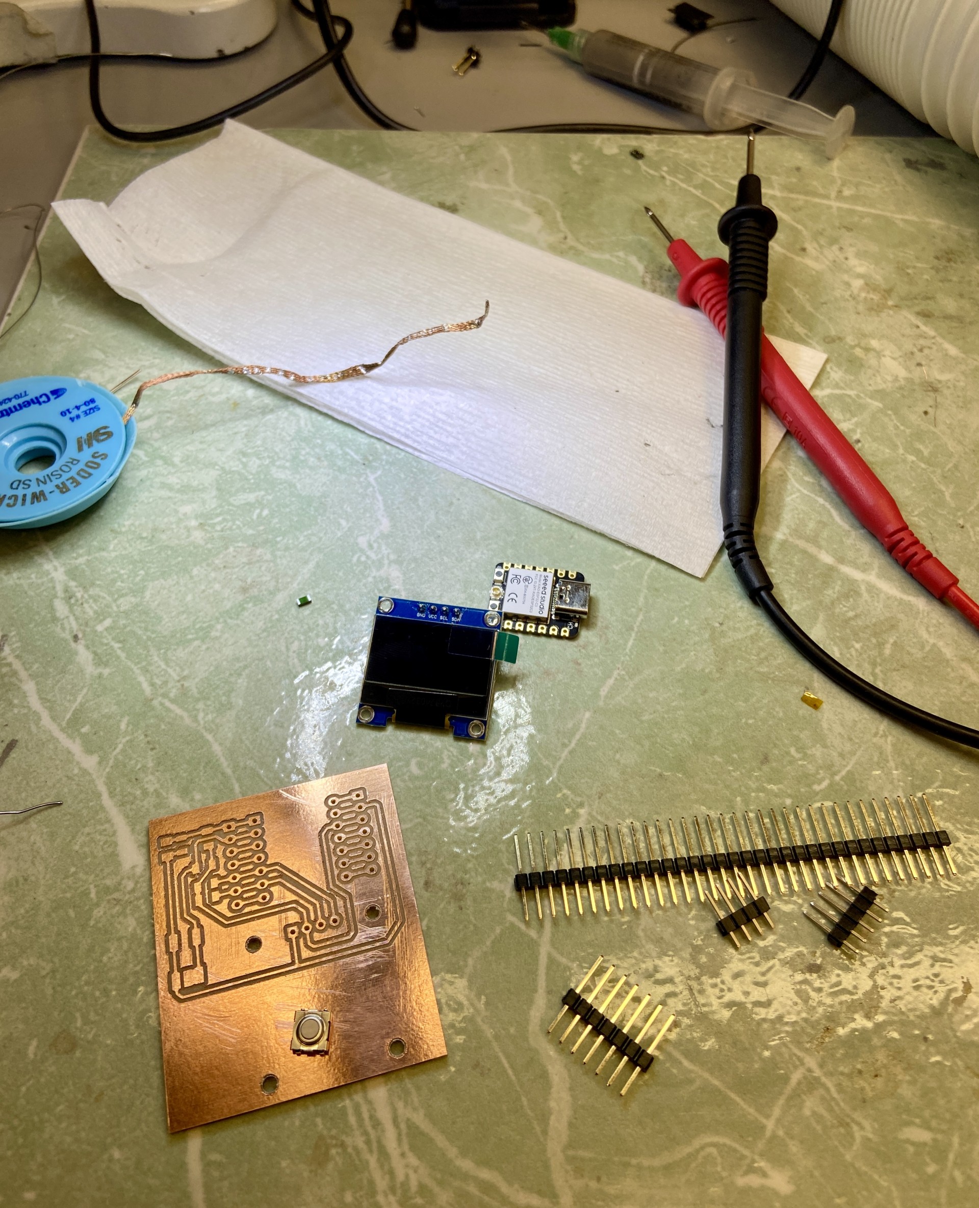
Soldering the board. Far from perfect, but I definitely felt more comfortable with soldering this round. It was much smoother and significantly quicker as well
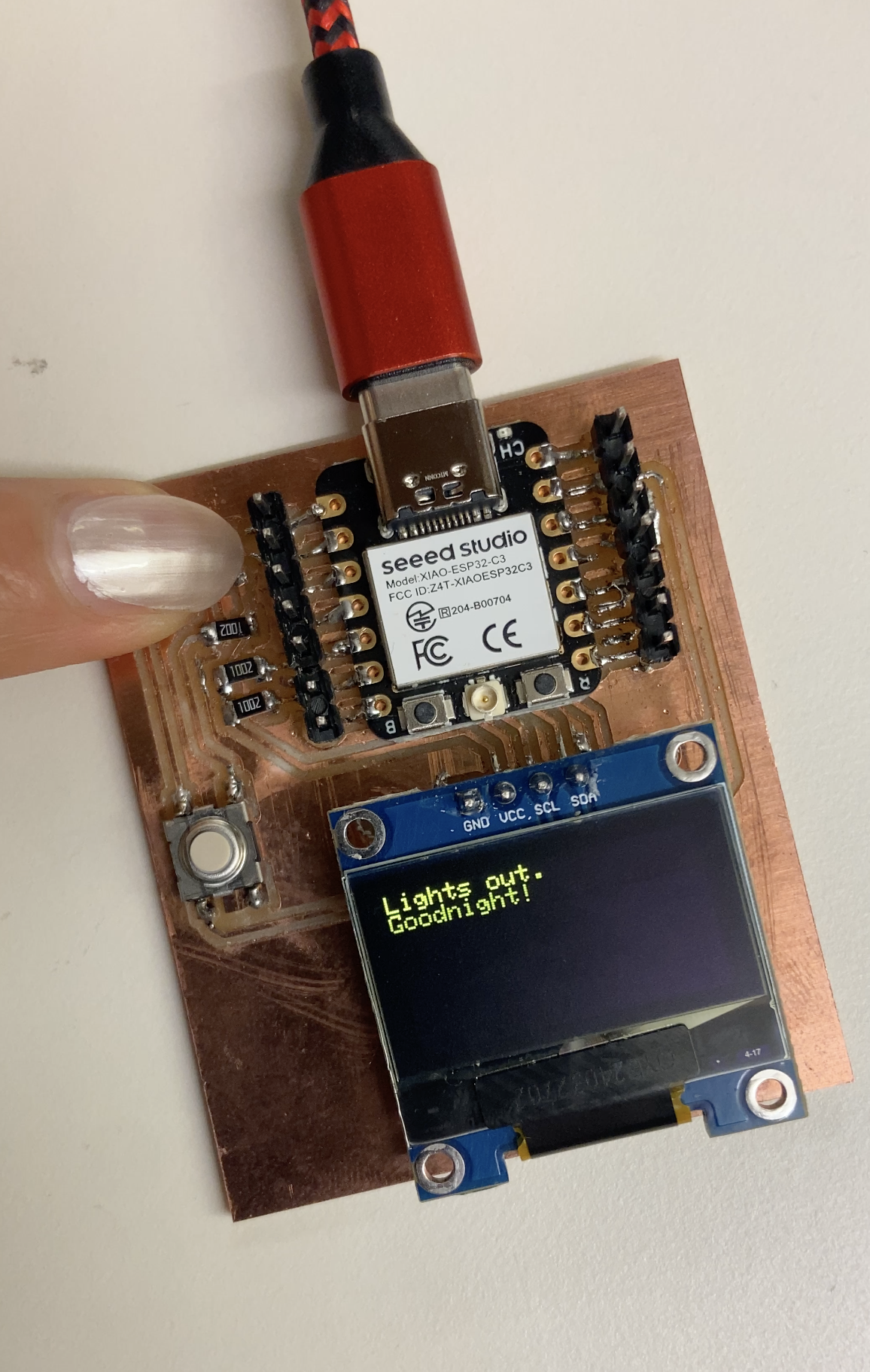
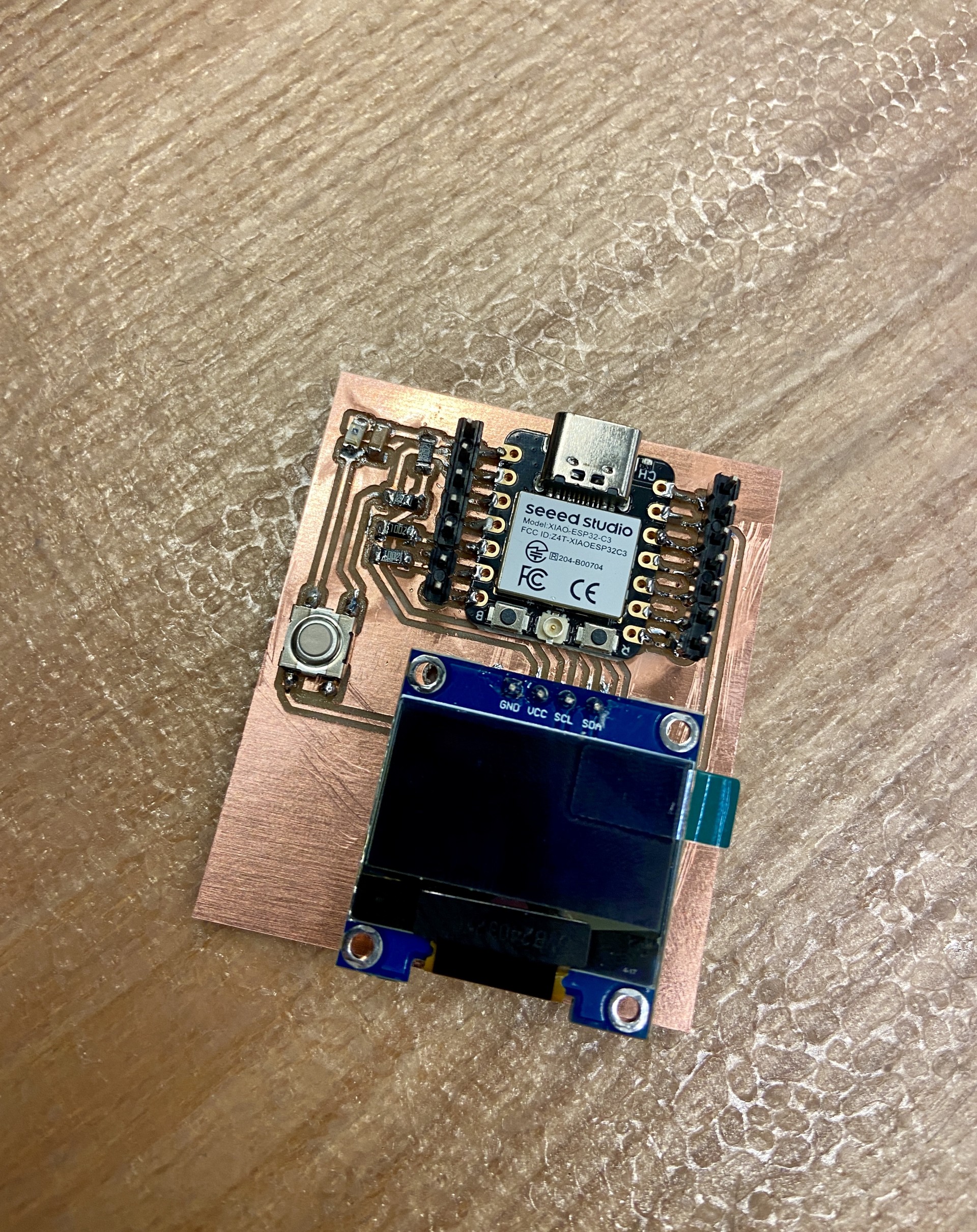
Completed board ft. phototransistor and OLED:
I wrote a program so that when the phototransistor detects light and when the phototransistor doesn't, different types of messages are displayed on the OLED. This was done in Arduino IDE. The code and the demo can be found below:
#include Wire.h
        #include Adafruit_GFX.h
        #include Adafruit_SSD1306.h

        #define SCREEN_WIDTH 128        // OLED display width
        #define SCREEN_HEIGHT 64        // OLED display height
        #define OLED_RESET -1          // Reset pin
        #define LIGHT_SENSOR 1         // ADC pin for phototransistor
        #define LIGHT_THRESHOLD 1500

        Adafruit_SSD1306 display(SCREEN_WIDTH, SCREEN_HEIGHT, &Wire, OLED_RESET);

        void setup() {
          Serial.begin(115200);

          if (!display.begin(SSD1306_SWITCHCAPVCC, 0x3C)) {
            Serial.println(F("SSD1306 allocation failed"));
            for(;;);
          }

          display.clearDisplay();
          analogReadResolution(12);
        }

        void displayMessage(const char* message) {
          display.clearDisplay();
          display.setTextSize(1);
          display.setTextColor(SSD1306_WHITE);
          display.setCursor(0,0);
          display.println(message);
          display.display();
        }

        void loop() {
          int lightLevel = analogRead(LIGHT_SENSOR);
          Serial.println(lightLevel);    // For debugging

          if (lightLevel > LIGHT_THRESHOLD) {
            displayMessage("Woah, it's bright out!\nLet's get the day going!");
          } else {
            displayMessage("Lights out.\nGoodnight!");
          }

          delay(1000);
        }
When the transistor is covered and light is blocked, the below message is displayed: