PCB design and fab...again?
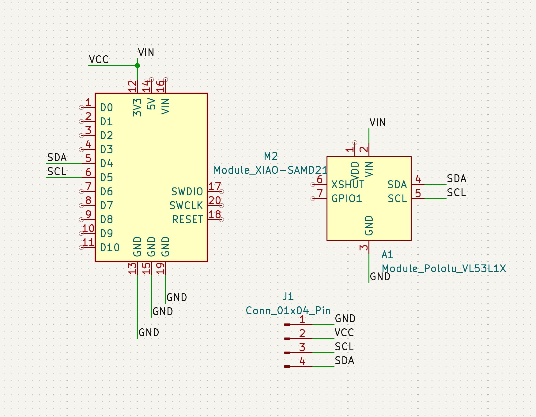
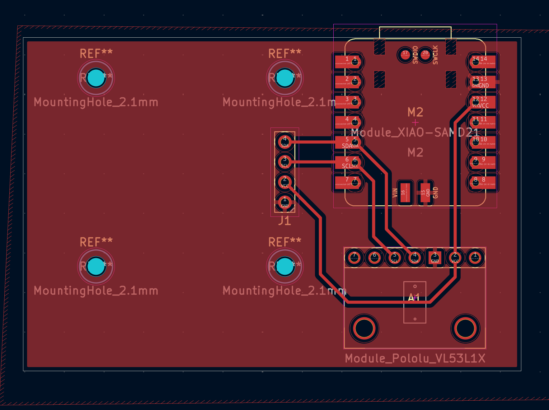
So, I attempted to make almost the exact same thing during PCB design and fabrication week, but it totally failed. I am almost 100% sure it was because I was using an RP2040, but I will get there in a bit.I did redesign it slightly (again) to have a OLED screen, since in my last iteration with the RP2040, my serial monitor would not connect since I was connecting via UF2. I am also using a XIAO SAMD21 and the Pololu VL53L5CX Time-of-Flight 8x8 Zone Distance Sensor Carrier.
Then I exported my gerbers and drill files to make my pngs for mods.
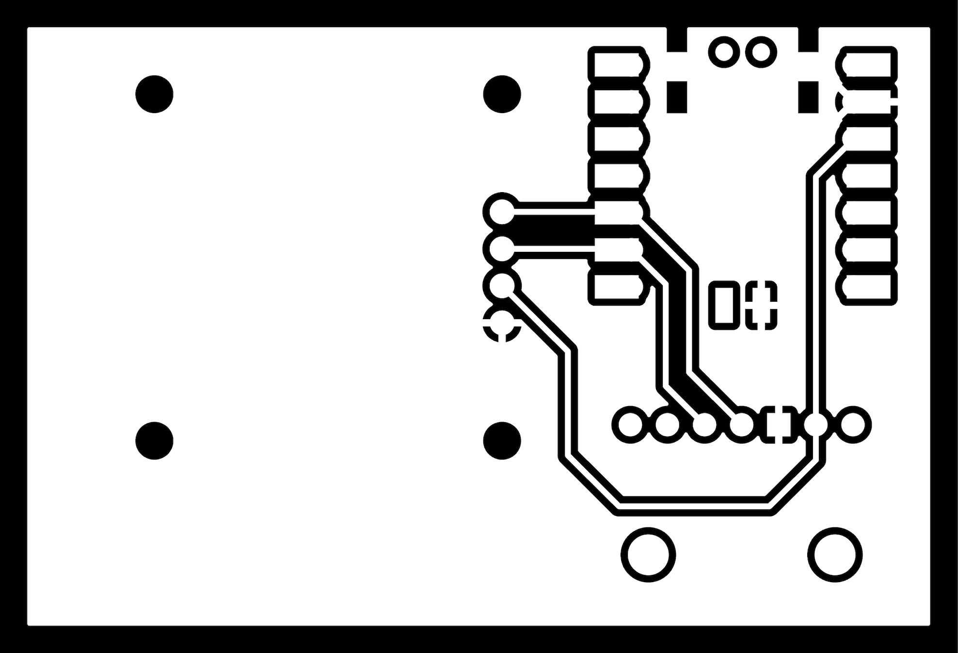
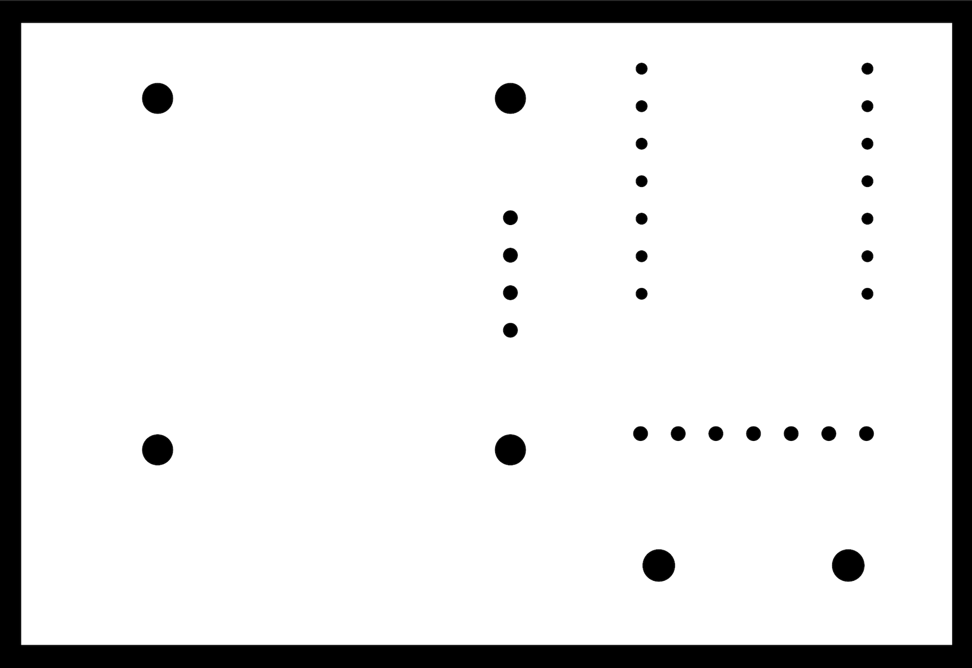
Then I set it up on the Carvera and milled my PCB. I think perhaps the endmill was reaching the end of its little life, as my traces were a little rough.
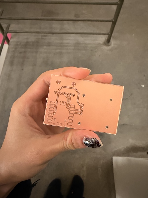
But fret not I did! I sanded it with very fine sandpaper and it improved.
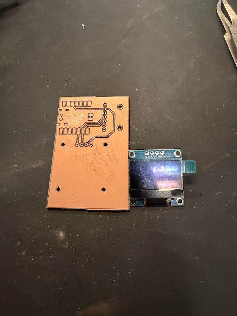
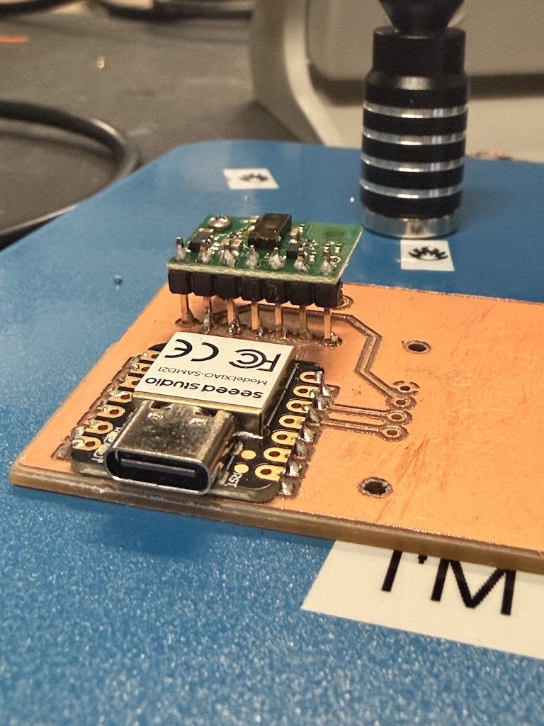
Alas. Maybe you noticed before me, but it appears my connector in Kicad was inverted and I didn't realize, so my screen would not fit on the way I had designed it. So, I got some header pins and decided to put the screen on the back. I think this makes sense as well, so you can move the whole sensor and see the reading on the back.
I love soldering!!!!!!!
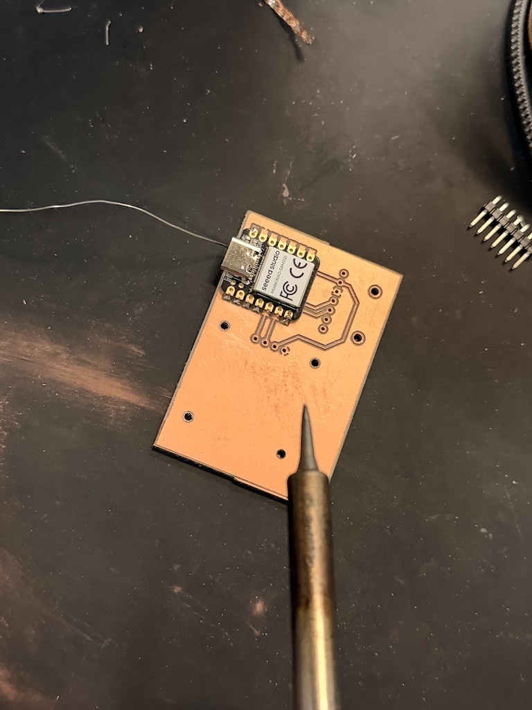
Once the header pins were soldered, I realized I wanted something to hold the rest of the parts in place so they wouldn't snap off (recall embedded programming week...). So I got these little teeny tiny screws from the shop. There were only a grand total of 3 hex nuts that fit, so I had to make do.
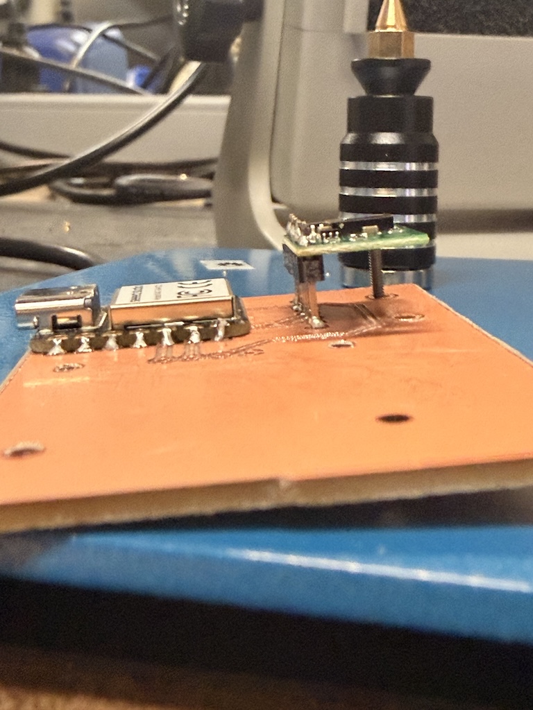
Here is the screw in the distance sensor - I used two nuts to hold it upright.
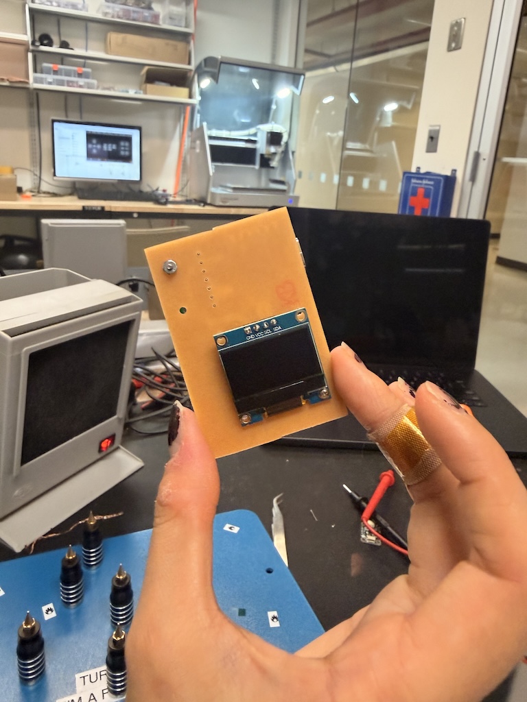
Then I added the screen on the backside and secured it with another screw.
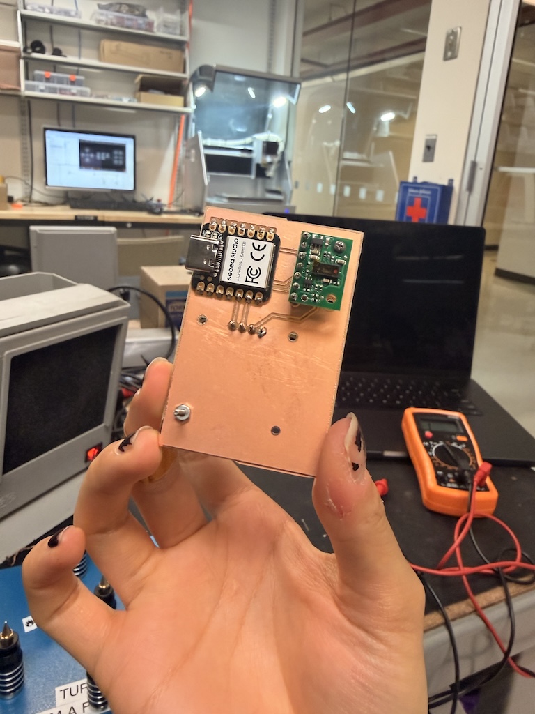
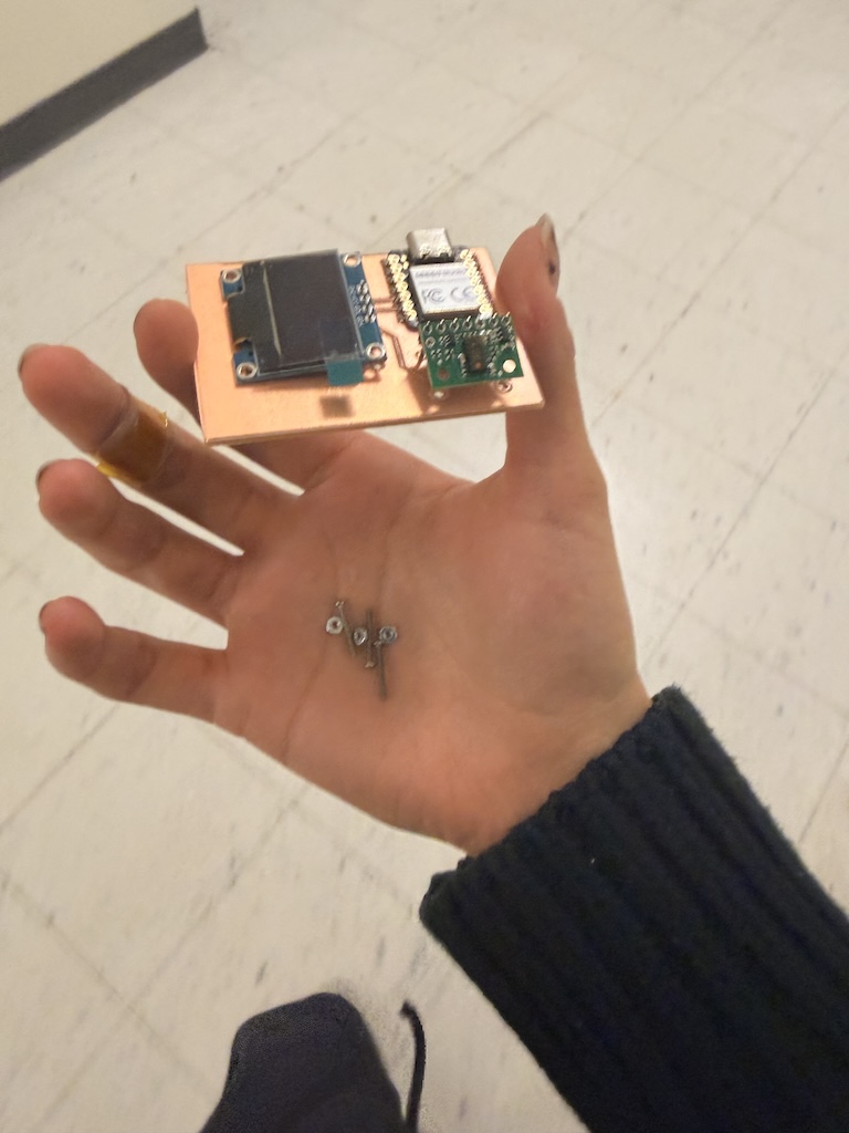
Here is the front!
programming
I started by downloading Seeed SAMD boards to my library, and got some sample code from Chatgpt just to make sure everything is able to connect and works. Here is my Chatgpt conversation.Initially, my board was not initializing the sensor, and I discovered it was because I needed to download the VL53L5CX library as well, so I did that, and then it worked!
The plan for next week is to connect a motor and have it activate at a certain distance. I also want to be able to write my own code, so I am learning from the code Chatgpt gave me.
#include
#include
#include

// ---- OLED ----
#define SCREEN_WIDTH 128
#define SCREEN_HEIGHT 64
#define OLED_ADDR 0x3C
Adafruit_SSD1306 display(SCREEN_WIDTH, SCREEN_HEIGHT, &Wire, -1);

// ---- VL53L5CX ----
#include   // SparkFun VL53L5CX Arduino Library
SparkFun_VL53L5CX myImager;

// Optional: shutdown pin if you wired LPn to a GPIO; else set to -1 and pull LPn HIGH in hardware
const int LPN_PIN = -1;

// Helper to draw the value
void drawDistance(float cm, bool valid) {
  display.clearDisplay();
  display.setTextColor(SSD1306_WHITE);

  display.setTextSize(1);
  display.setCursor(0, 0);
  display.println(F("VL53L5CX Center (cm)"));

  if (!valid) {
    display.setTextSize(2);
    display.setCursor(0, 18);
    display.println(F("No data"));
    display.display();
    return;
  }

  display.setTextSize(2);
  display.setCursor(0, 18);
  display.print(cm, 1);
  display.println(F(" cm"));

  // Progress bar 0–200 cm
  float v = cm; if (v < 0) v = 0; if (v > 200) v = 200;
  int w = map((int)(v * 10), 0, 2000, 0, SCREEN_WIDTH);
  display.drawRect(0, 44, SCREEN_WIDTH, 14, SSD1306_WHITE);
  display.fillRect(0, 44, w, 14, SSD1306_WHITE);

  display.display();
}

void i2cScanOnce() {
  Serial.println(F("Scanning I2C..."));
  for (uint8_t addr = 1; addr < 127; addr++) {
    Wire.beginTransmission(addr);
    if (Wire.endTransmission() == 0) {
      Serial.print(F("Found 0x")); Serial.println(addr, HEX);
    }
  }
}

void setup() {
  Serial.begin(115200);
  uint32_t t0 = millis();
  while (!Serial && millis() - t0 < 1500) {}

  if (LPN_PIN >= 0) {
    pinMode(LPN_PIN, OUTPUT);
    digitalWrite(LPN_PIN, HIGH); // keep sensor awake
  }

  Wire.begin();             // XIAO SAMD21: D4=SDA, D5=SCL
  Wire.setClock(400000);    // VL53L5CX handles 400kHz

  // OLED init
  if (!display.begin(SSD1306_SWITCHCAPVCC, OLED_ADDR)) {
    Serial.println(F("SSD1306 init failed"));
    while (1) { delay(10); }
  }
  display.clearDisplay();
  display.setTextSize(1);
  display.setTextColor(SSD1306_WHITE);
  display.setCursor(0, 0);
  display.println(F("Init VL53L5CX..."));
  display.display();

  // Quick scan to verify address (should see 0x29 for VL53L5CX and 0x3C for OLED)
  i2cScanOnce();

  // Sensor init
  if (myImager.begin() == false) {
    Serial.println(F("VL53L5CX init FAILED. Check wiring/LPn/I2C."));
    display.setCursor(0, 12);
    display.println(F("Sensor init FAIL"));
    display.display();
    while (1) { delay(10); }
  }

  // Configure sensor: 8x8 @ 15 Hz is a good start
  myImager.setResolution(VL53L5CX_RESOLUTION_8X8);    // 64 zones
  myImager.setRangingFrequency(15);                   // Hz (1..60, depends on resolution)
  // Optional: myImager.setIntegrationTime(5);        // ms (0=auto). Use 5–20 for stability.
  myImager.startRanging();

  display.setCursor(0, 12);
  display.println(F("OK, ranging..."));
  display.display();
  delay(400);
}

void loop() {
  // Data structure from SparkFun lib
  VL53L5CX_ResultsData measurement; // contains .distance_mm[64]

  // Wait for a fresh frame
  if (myImager.isDataReady()) {
    if (myImager.getRangingData(&measurement)) {
      // Compute a center reading (avg of the middle 2x2 block)
      // 8x8 indices (row-major), rows 0..7, cols 0..7
      // center 2x2 = rows 3..4, cols 3..4
      const int idx33 = 3 * 8 + 3;
      const int idx34 = 3 * 8 + 4;
      const int idx43 = 4 * 8 + 3;
      const int idx44 = 4 * 8 + 4;

      // values are in millimeters; 0 or 0xFFFF typically indicate invalid
      uint16_t d33 = measurement.distance_mm[idx33];
      uint16_t d34 = measurement.distance_mm[idx34];
      uint16_t d43 = measurement.distance_mm[idx43];
      uint16_t d44 = measurement.distance_mm[idx44];

      // Filter invalids and average the valid ones
      uint32_t sum = 0; int count = 0;
      uint16_t vals[4] = { d33, d34, d43, d44 };
      for (int i = 0; i < 4; i++) {
        if (vals[i] > 0 && vals[i] < 4000) { sum += vals[i]; count++; }
      }

      bool valid = (count > 0);
      float cm = valid ? (sum / (float)count) / 10.0f : 0.0f;

      // Debug to Serial
      Serial.print(F("Center cm: "));
      if (valid) { Serial.println(cm, 1); } else { Serial.println(F("N/A")); }

      // Draw to OLED
      drawDistance(cm, valid);
    }
  }

  // modest loop pace
  delay(5);
}
Files