Design
This week was PCB design! Yay! It's something I've never done before, but was excited to tackle. If I said I was not still confused after this week, I'd be lying. But I feel like I made small progress and will keep improving!Even though it was my first ever PCB, I wanted to make more than just a button with a light. I knew for my final project that I will want to incorporate a distance sensor, so I searched the inventory for one.
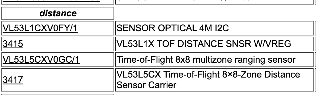
I came across the VL53L1CXV0FY/1 sensor, and so I got started in KiCAD.
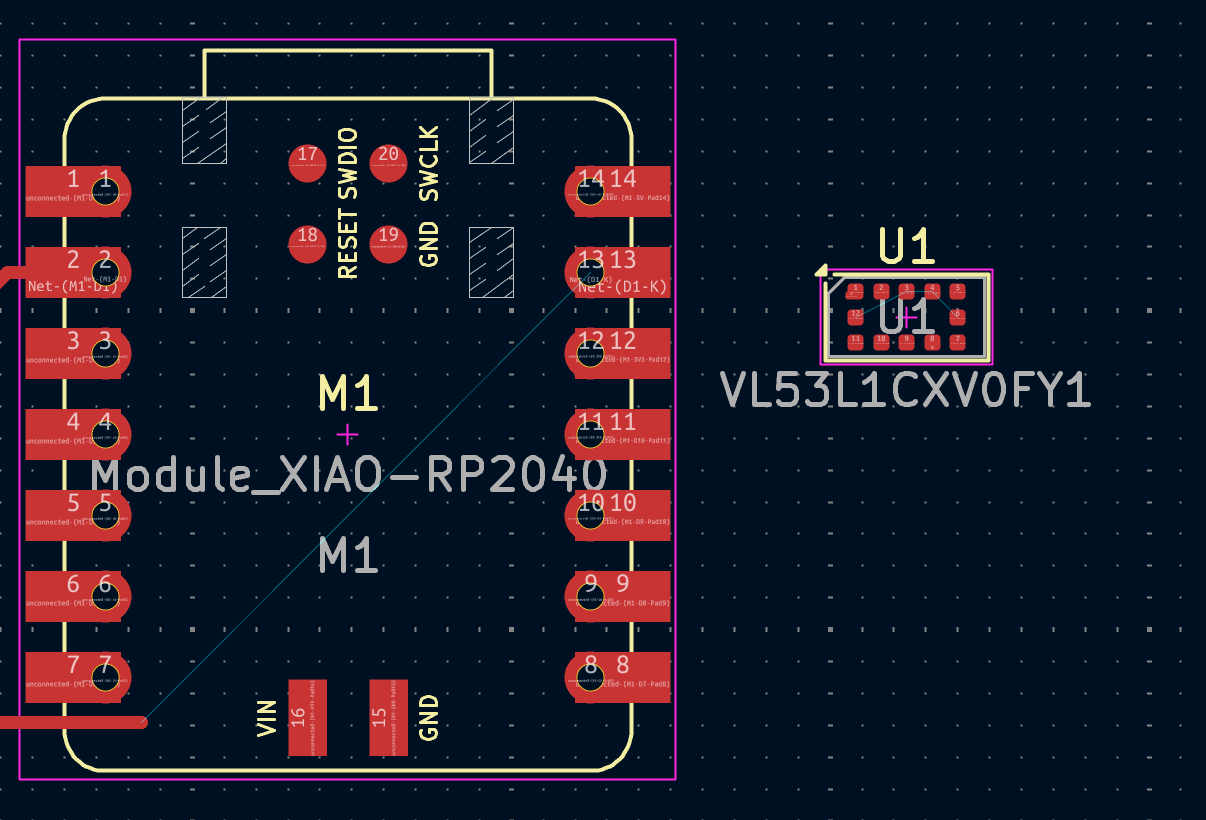
I searched it up in the symbol library, and there it was! But it was so so so tiny, which I did not realize until I switched to PCB mode... Here it is against a Xiao RP2040!
Then, I asked ChatGPT to help me figure out how to connect it to my Xiao RP2040. It was super confusing honestly... I guess I went into it with very limited knowledge on what capacitors and resisstors even do. Here is a link to the conversation, although it was not particularly helpful and I changed all of it later. This is also unfinished and wrong since I got confused.
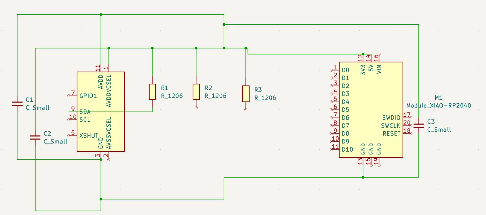
Here it what I learned!
- Capacitors work as little batteries to store energy and help stabilize voltage in circuits. In my case here, they are used between AVDD and GND, and AVSSVCSEL and GND. They are meant to "shock absorb" voltage to protect the sensor itself.
- Resistors regulate the flow of electrical current and prevent damage to components. I did not finish connecting them in this schmeatic, but they would serve as pull up resistors to pull the SDA and SCL to 3.3 V.
But anyway, as I said before I was a little confused and intimidated by the tiny size of the sensor. In the pcb editor, the ratsnest was connecting everything... nothing was making much sense... SOOOOOO I went to office hours!
There, Alan helped me figure out that the sensor actually has an Adafruit board that is premade.
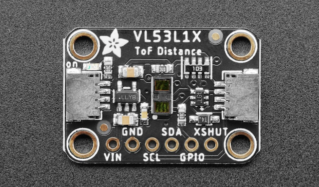
Yippe!! This made my life so much easier. PHEW!
So, instead of wiring all of the little components up and having to solder them myself, I simply created a 6 pin connector so I could use this board. Alan helped me set it up. Thanks, Alan!!
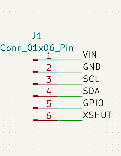
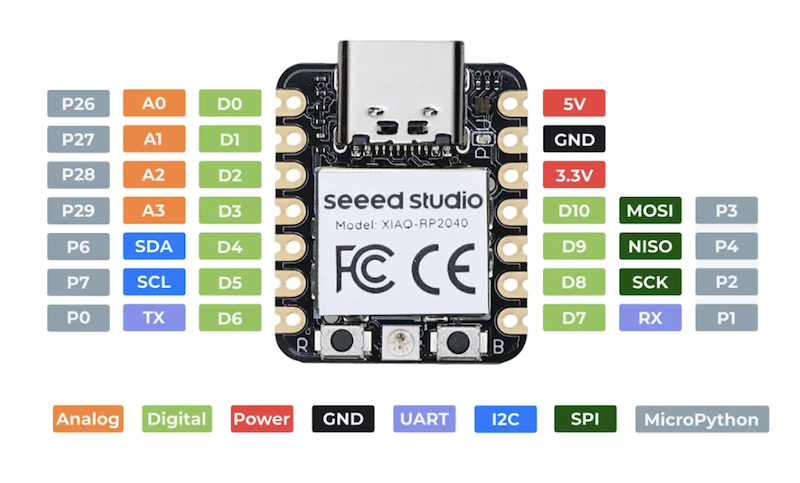
I set up the connector pin with labels so it matched the Adafruit one. Then, using the datasheet from the Xiao RP2040 and the Adafruit Sensor, I connected SDA to D4 and SCL to D5.
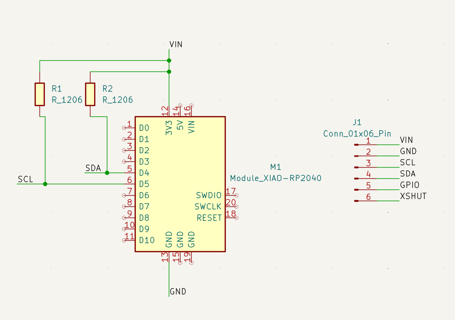
It was unclear to me whether there were resistors already on the board (I assume there are...) so I just added some anyway just in case.
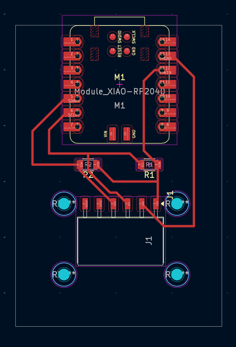
Here is the final PCB layout. I'm sure there is a more efficient way to layout the traces and such... but I think I did an okay job!
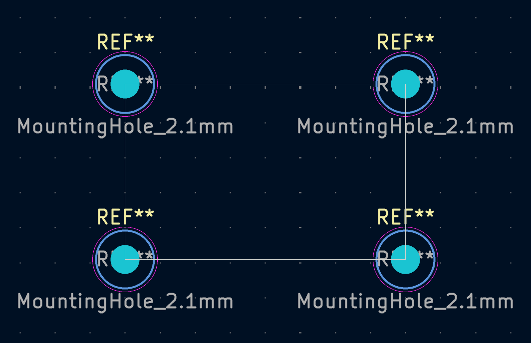
The mountholes are for the Adafruit board, and I created them using the specs given:
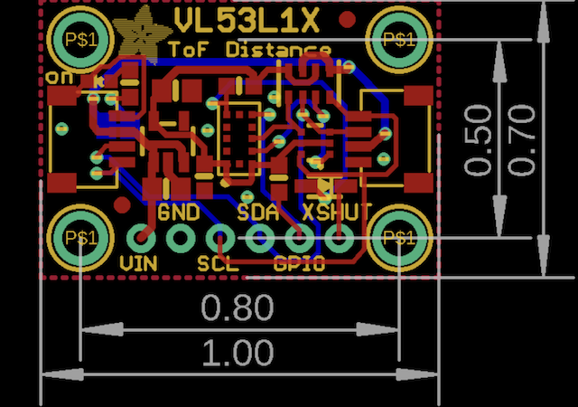
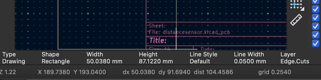
I also realized the importance of grid size!! The specs given for the adafruit are in inches, and I was struggling at first to get the measurements correct. But, I realized that even though the grid units were in mm, they had a size that was in increments of inches in mm, so 0.2540 mm. This was super helpful!!
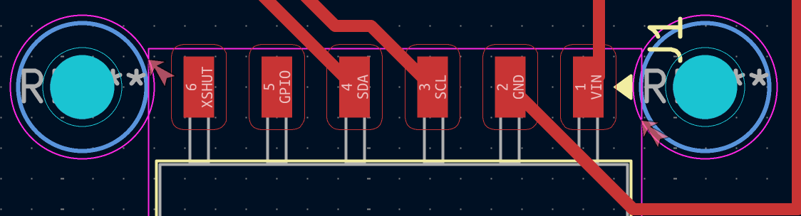
I was also having some issues with trace width. I started doing it with the default trace width, which was very tiny. So I deleted everything, changed it to 0.4 mm, but some of the traces kept showing up super skinny.
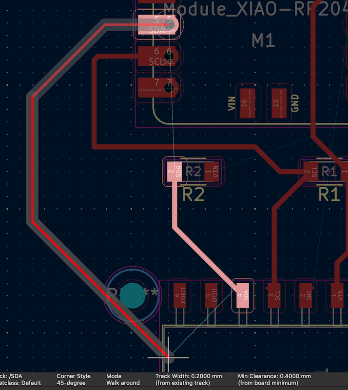
As you can see here, the one the left was much tinier than the rest. I was like whaaaaa why???? It took me a little while to figure it out.
But I discovered that it was adjusting the width to an exisitng trace, and I had so many teeny tiny little dots of old traces hidden in the holes of the components. Super annoying to go through and find all of them!! I ended up just deleting everything and re-updating the PCB to remove them. It worked out in the end though!
Then, I used the design rules checker to make sure everything was good. But alas! I had two errors!
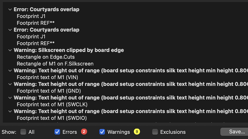
But I did not fret. The errors were from the mount holes slightly overlapping with the bounds of the connector, but I do not think it will make any difference on the actual PCB.
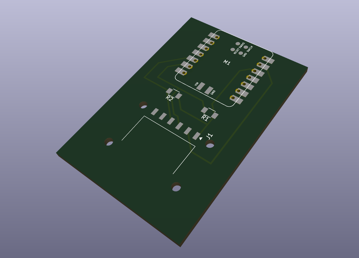
Here is the 3D version!
Simulation?
Soooooo. This is where I am a bit unsure. I ran KiCAD's ERC to see if there were any connection problems, and I got tons of errors at first because loads of pins were disconnected. But I added power and no connect flags and then everything was good.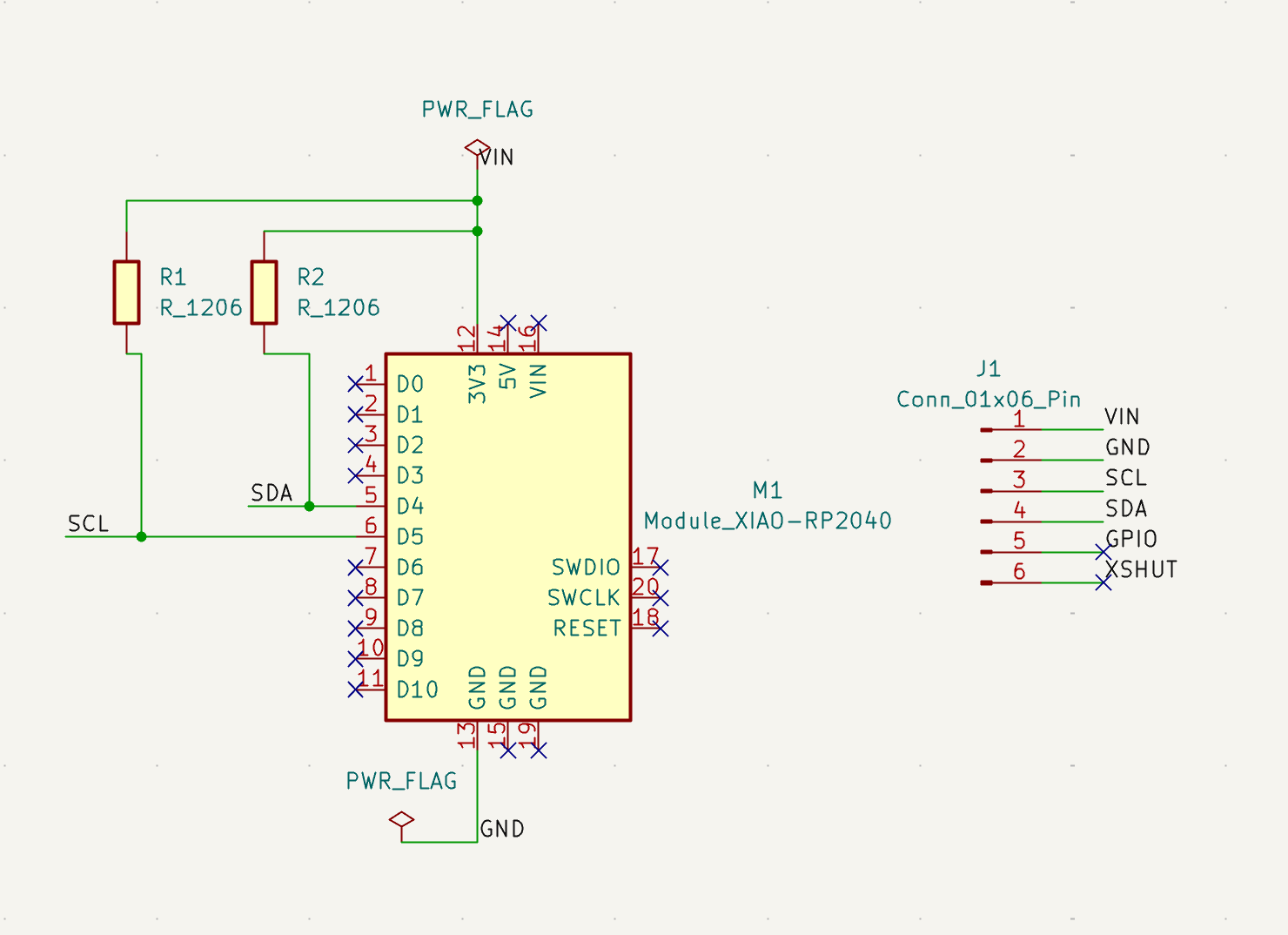
Then, I was trying to figure out what would be a good way to simulate this since I would be using a preexisting board, and KiCAD does not have simulation integrated. So, I used Wokwi with some stand-in components.
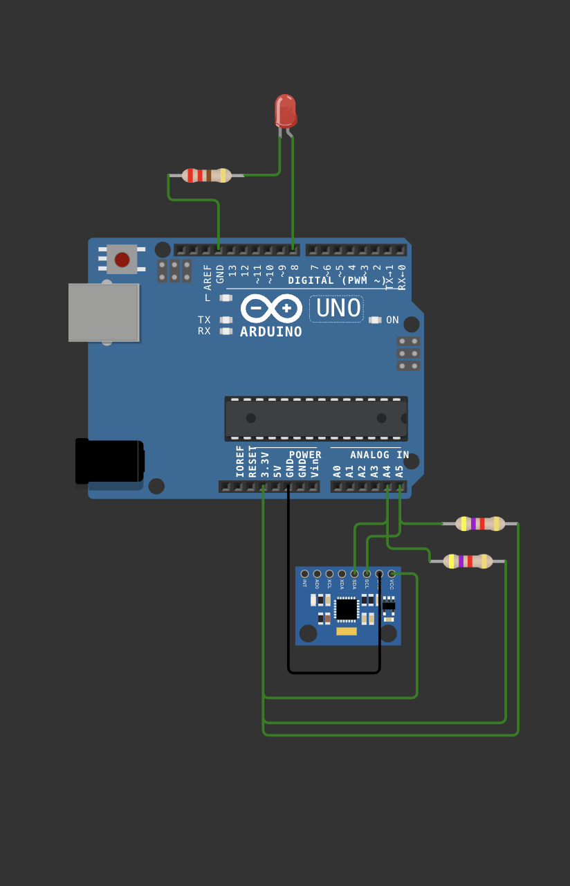
I asked ChatGPT to help me figure out how to simulate what I had in KiCAD in Wokwi. Basically, I am using an Arduino UNO board in place of my Xiao RP2040, a MPU6050 Accelerometer + Gyroscope instead of my VL53L1CXV0FY (since they are both I2C and have SDA/SCL), and kept my 2 resistors. I also added a little LED for fun and to show that the sensor is recognized.
Here is the code I ran:
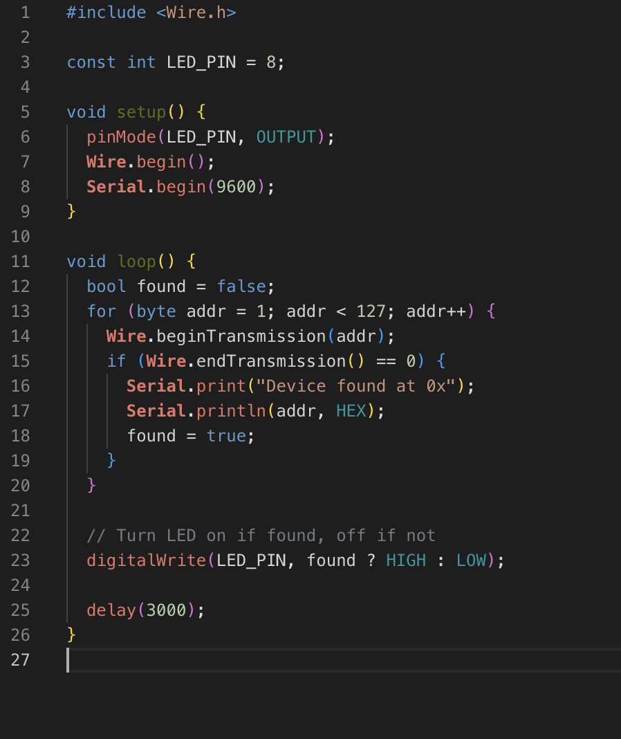
So the microcontroller searches for an I2C device, and if it finds one, it turns on the LED. Even though I am not simulating the funciton of the distance sensor, I was able to simulate that my wires and things generally work, and that the microcontroller would be able to read an I2C device. Here is ChatGPT. (I started a new one with other info because I accidentally used the old one for something else and all of the information got mixed up)
Files (but i think some of my original files got lost / changed when i moved to prod week)