Redesign
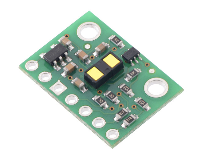
Last week, I designed a PCB around Adafruit's VL53L1X Time of Flight Distance Sensors, since I found a VL53L1X in the inventory. But little did I know, we had a similar time of flight sensor in the inventory right below it, and I didn't even check it out. I found it now! And I redesigned my PCB around it. It is the Pololu VL53L1X Time of Flight Distance Sensor.
Little did I know again, that there actually Adafruit Time of Flights in CBA stock as well. But I continued with the Pololu since I already remade it.
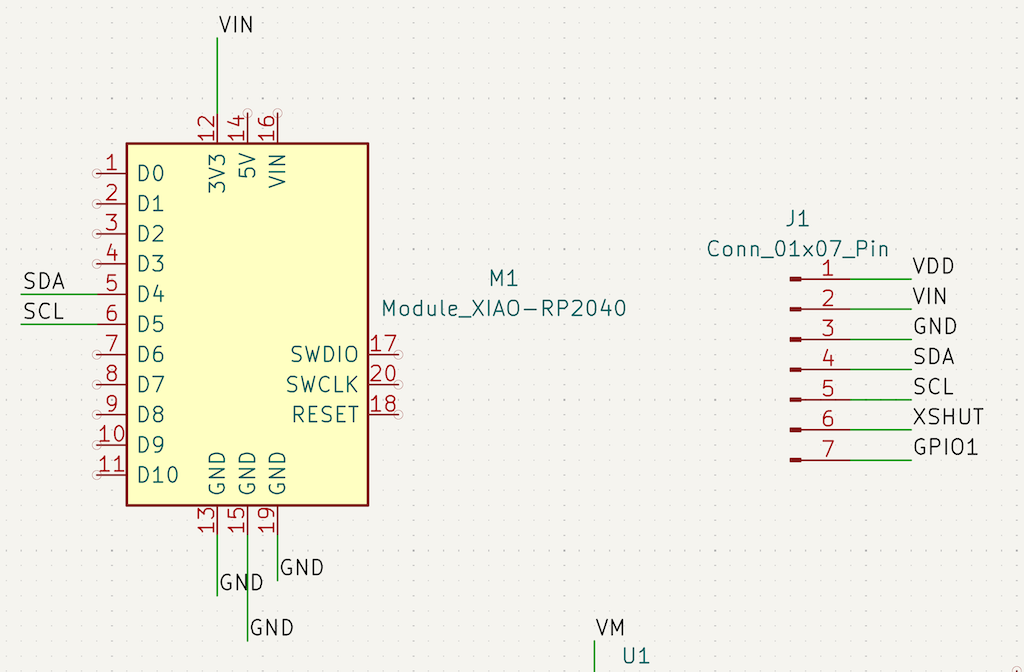
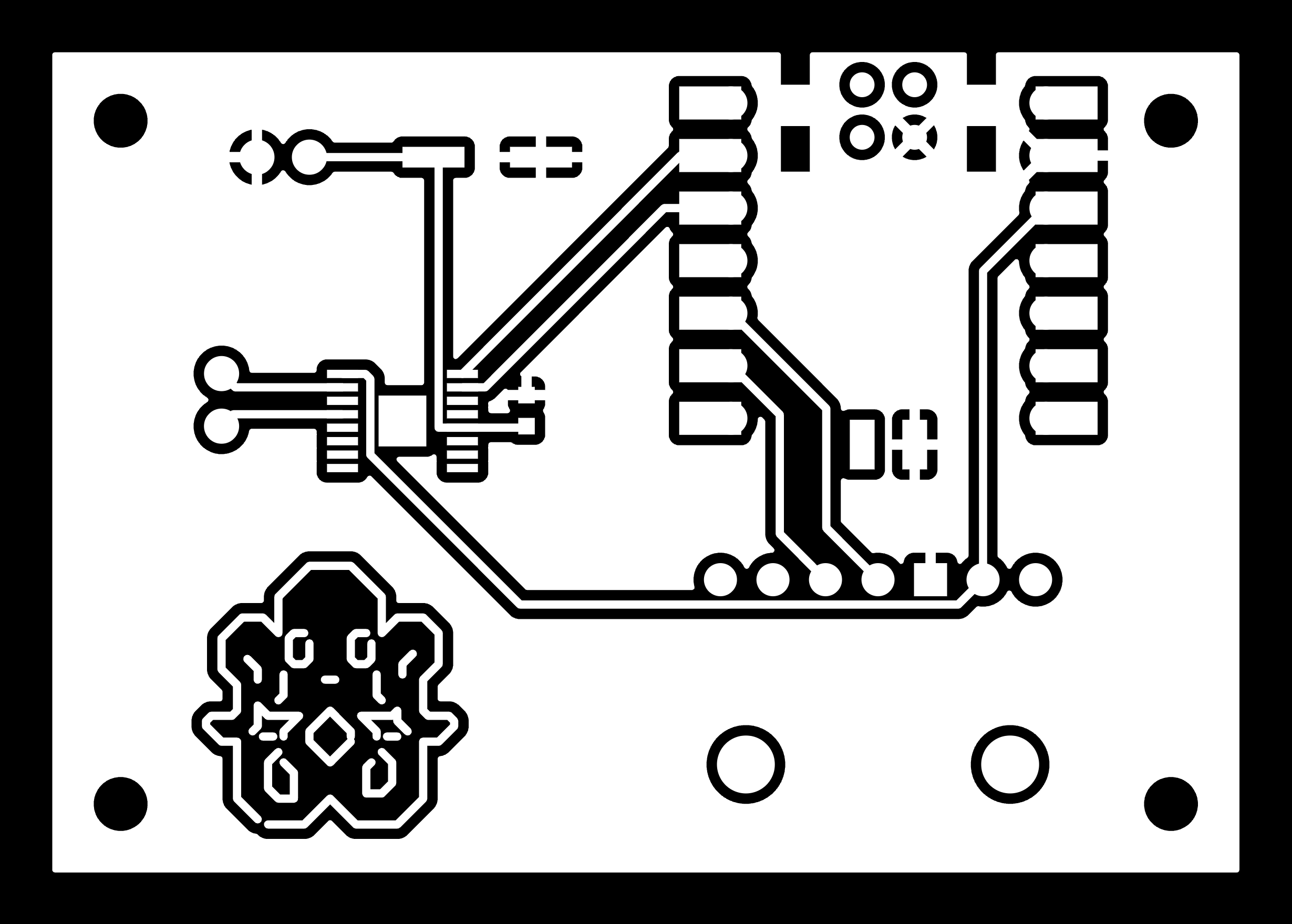
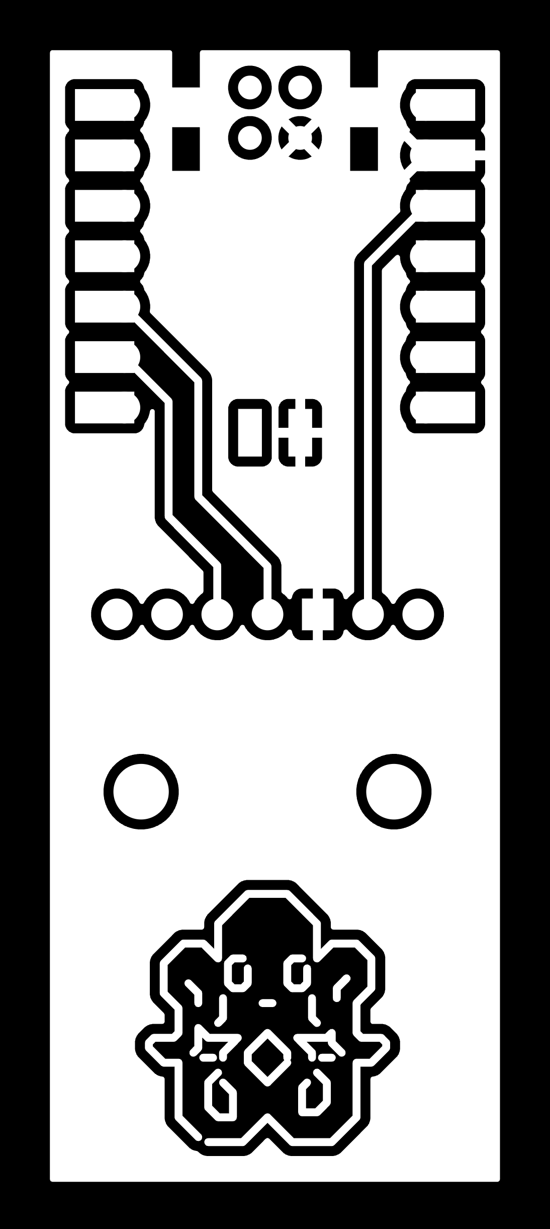
So, I made a simple and tiny pcb as a test to mill. I used the Pololu VL53L1X and a XiaoRP2040.
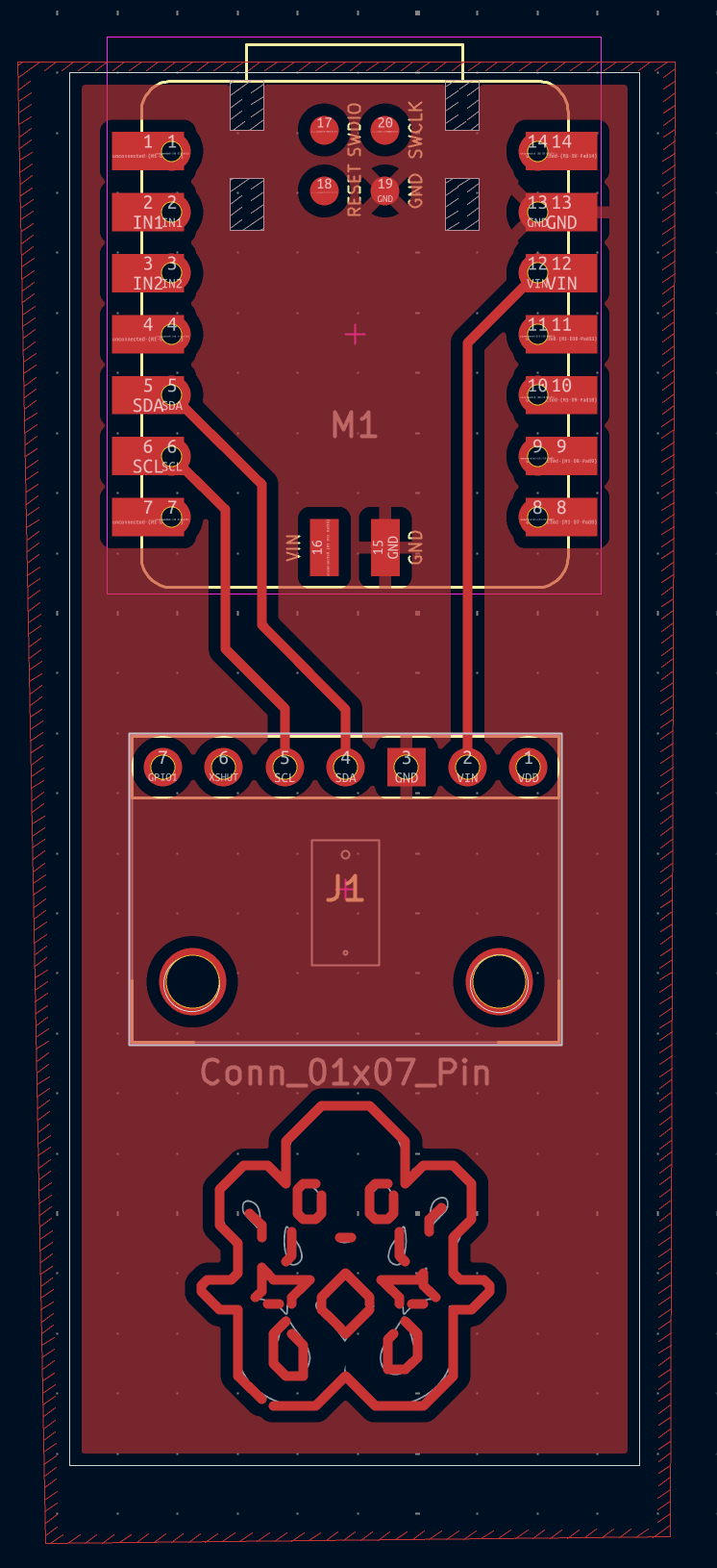
And of course I had to add my little octopus!
I also decided I wanted to work a bit more towards my final project, and try to use a motor. So I checked the inventory and came across a WWZMDIB DC motor, which I thought would work for my purposes of pulling tentacle cables. In retrospect, I realize now that maybe a servo motor might be better?? But still looking into it...
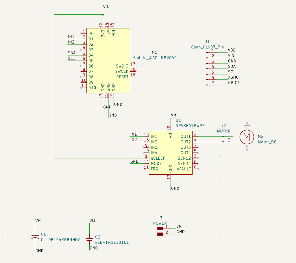
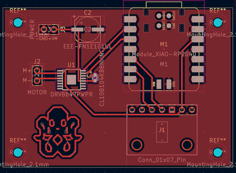
So I designed a new PCB keeping the Pololu distance sensor, but adding the motor and a DEV8847PWPR motor driver, as well as some capacitors. Here is my ChatGPT conversation about this. I also needed an external battery for my motor which I accounted for. And octopus again.
Milling
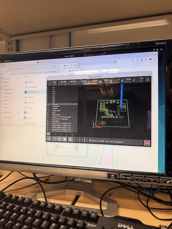
Now it was finally time to mill! I went downstairs, exported my smaller pcb gerber files, converted them to pngs, and put them in the computer. All was good and dandy!
Then I sent it to mill. Unfortunately... after it was finished, I saw that the edge cuts and traces were somewhat offset.
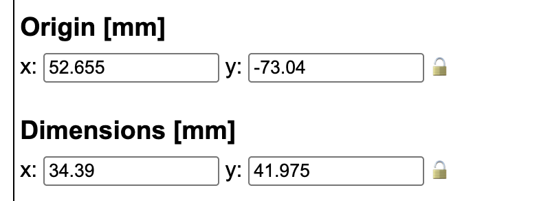
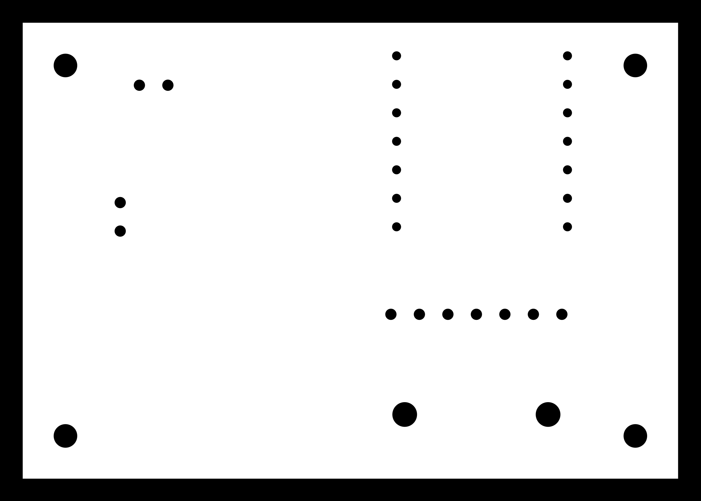
(This is also before I added my little octopus..) The mount holes (which I also drew by hand in edge cuts because I didn't realize I needed to export .drl files until later) and the edges were slightly shifted. I later realized that in Gerber2IMG, I needed to lock the dimensions so that the edge cuts png and trace png had the same size.
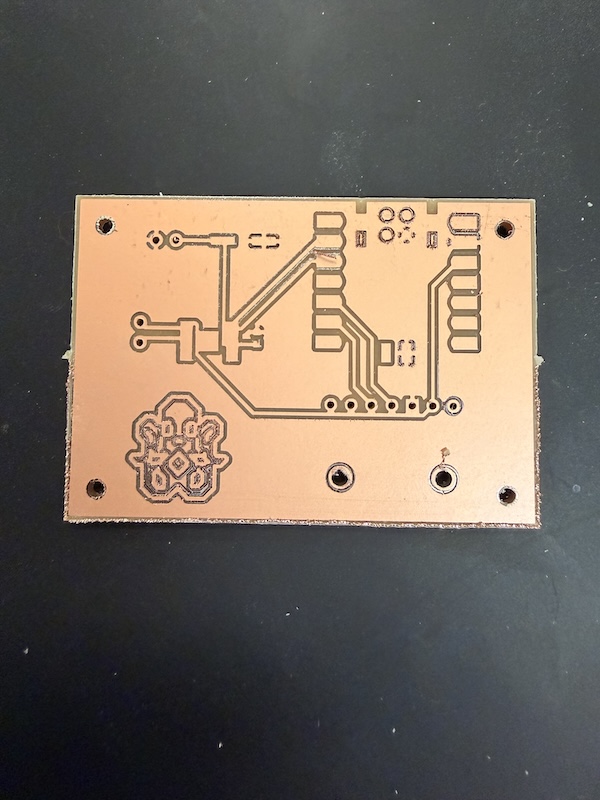
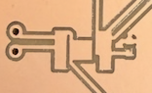
But anyway! Little test complete, generally successful. The traces looked pretty clean and good.
So now, I wanted to tackle the big one. I followed all of the steps and sent it to mill, this time making sure my dimensions were the same on the png.
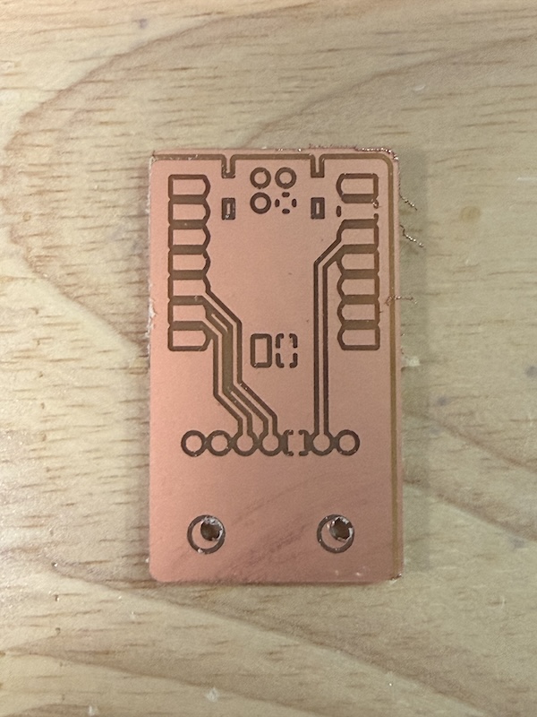
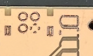
I sent it to mill! and nice, the holes were in the same spot, although it did not get the RP2040's holes.
Looks okay, right? WRONG. Let's take a closer look.
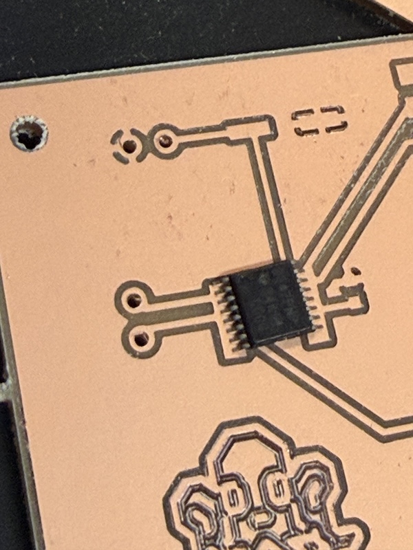
Sigh. Foolish me. It did not even articulate the driver's little tiny traces, which I should have anticipated.
BOOM. All of these are connected too. I put the trace below WAY too close to the pins in my pcb and I did not even notice. SILLY ME!!
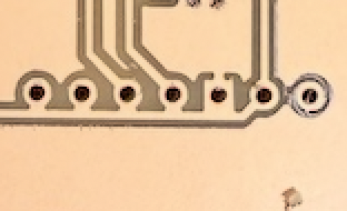
And as if it could not get worse, the mill did not even get all the way through the copper in some places.
But no matter. I decided to scrap this for now (I ordered a driver breakout board for later) and move on to doing just the distance sensor.
I for some reason did not take a picture of the board right out of the machine, but we can see it as I started assembling.
Assembly
Since I was away, I ordered my own Xiao RP2040 because I was worried there would not be any in stock when I got back, and lucky I did! I decided to start with soldering throughhole pins for my sensor, since soldering directly to the pad was a little daunting.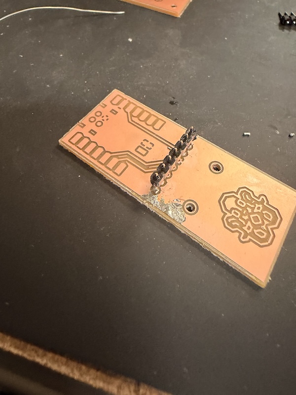
I made a big spillage of solder though...... it was not damaging anything but it kinda looked scary. I made sure it was not connecting anything using a multimeter.
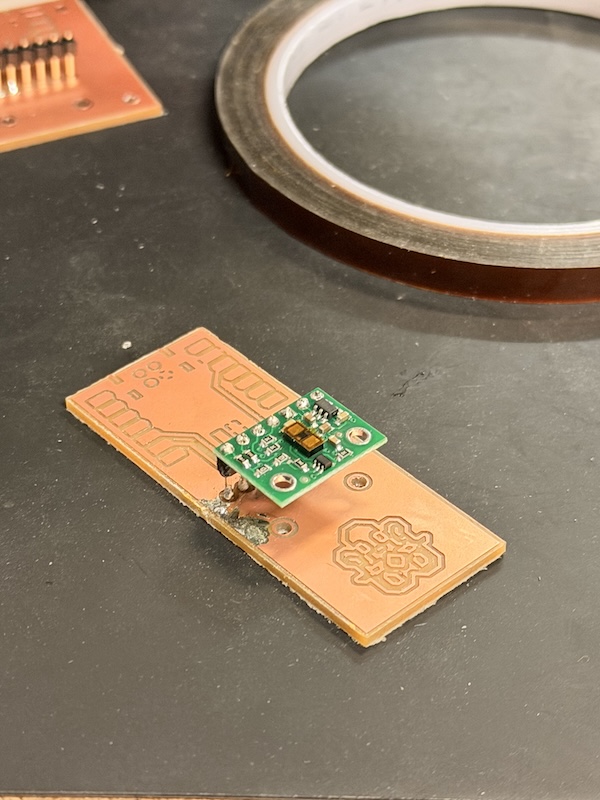
Then, I soldered on the sensor, checking with a multimeter every step.
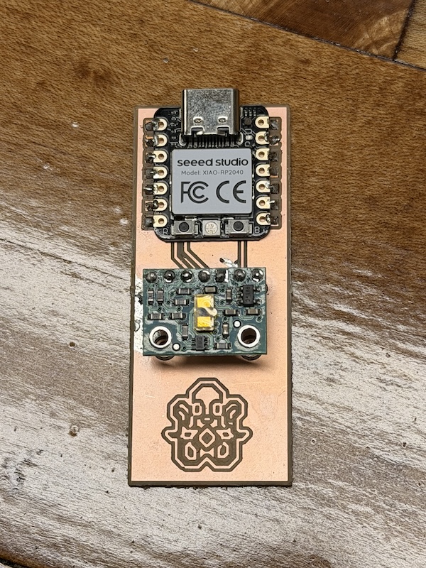
Then, I added my RP2040. and everything seemed connected and good! Or was it....
Programming
More like *attempted* programming. IF YOU ARE READING THIS I HAVE STILL NOT FIGURED IT OUT.Sigh. The RP2040 works for sure, which is a little victory, I suppose. But I cannot get the sensor to work, nor can I even get my serial monitor working?? I think I am just having trouble with using Arduino and the RP2040 in general.
I have to put it in bootloader mode everytime I want to run new code, and it connects as UF2 board, not as a usb connection. The serial monitor only works when it is the usbmodem port, but I cannot seem to use that, since it does not connect unless I enter bootloader mode, and when I do that, it connects via UF2.
Basically what I've been doing is: I connected the board using a usb cord to my computer. I tested to see if the cord or microcontroller were a problem using a code for flashing LED, which worked. I then tried a code to use the distance sensor and serial, but nothing happened. So maybe it is a hardware connection problem, although I made sure everything was connected. Maybe I totally wired things wrong, but I made sure my SDA and SCL went to the correct pins in the RP2040? And then maybe it is a me problem using Arduino and coding. And using ChatGPT. I am stuck in a weird limbo where I do not trust ChatGPT and the code it gives me, but also I am kind of reliant on it for now while I'm figuring it out.
So, I have two things to figure out:
- why I cannot connect through the usbmodem port
- whether or not the sensor works (which I think it does not)
To test the sensor without the need for serial, I was using ChatGPT to make code to flash LED when different distances were recognized. Nothing happened when I tried this. I also tried to see if the I2C connection was even there by flashing LEDs, again nothing. So I am under the impression that the sensor either does not work, I did not make the right connections, or did not solder properly.
I am planning on sorting this out this week, as well as trying a new motor and breakout board to work towards the final project. I may also try a different microcontroller, since RP2040s give me grief.
Also, I have lost some of my Kicad files, so some of the original files are missing from here.
Files