
Final Project: *Glowmorph*
Research Description
5-second read TLDR
Glowmorph: a living, shapeshifting lamp that breathes, dances, and responds to its surroundings like a moody roommate with good (or potentially questionable) vibes.
30-second read
The following is the progress of my final project: Glowmorph. It is a lamp. It moves. More specifically, I am imagining a living, shape-shifting lamp that retracts and expands in response to its surroundings. Will it be a lighting fixture that is introverted and shy, or extroverted and animated by nearby crowds and movements? Perhaps it responds to sounds or even dances to music. Its a playful object that blurs the line between object and organism. This project explores light as a living, responsive presence rather than a static fixture. The lamp will be constructed as an inflated or tensile membrane that can transform its geometry through air pressure or mechanical actuation. Im considering materials such as latex, nylon, or another stretchable skin. Its form is not fixed but mutable: it expands, contracts, and reshapes itself in dialogue with external stimuli such as the day-night cycle, the presence of people, sound, or proximity. By linking light with responsive motion, the lamp becomes a performer—alternately shy or expressive, retreating when approached or dancing to music. Im drawn to how this can explore the tension between attraction and withdrawal, desire and distance, presence and absence. At once organic and technological, the lamp blurs the boundary between inert object and animated being, suggesting a new kind of domestic companion: one that glows, breathes, and responds to its environment in unexpected ways.
Inspiration
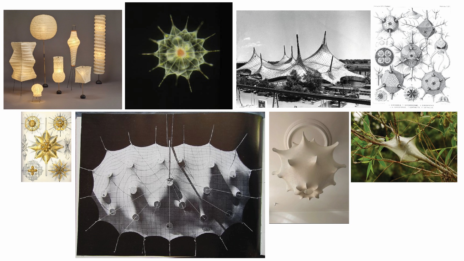
Above, clockwise from top left: Noguchi Akari Lamps, microscopic image of an Acantharian, Frei Otto Expo 1967, Haeckel drawings of Radiolaria, a tent built by tent caterpillars, Castiglioni's Pendant Lamp, Haeckel drawings of Acanthometra
Design, forms and nature
I am inspired by both Isamu Noguchis Akari lamps and the tensile and inflatable structures pioneered in the 1960s. Noguchis lamps are poetic and ephemeral, with delicate paper stretched over lightweight frames that reimagine traditional Japanese Gifu lanterns. Similarly, tensile and inflatable experiments of the 1960s, such as Frei Ottos membrane structures, explored flexible, adaptive forms that responded to environmental forces. Both precedents resonate with my interest in lightweight, transformable structures: minimal yet expressive, responsive yet intimate. Alongside these architectural and artistic references, I am also drawn to natural geometries. Ernst Haeckels illustrations of microscopic organisms such as Radiolaria and Acanthometra reveal intricate, symmetrical forms that are both delicate and dynamic. These organisms embody a balance of structure and fluidity, precision and adaptability—qualities that echo the design ambitions of Glowmorph. The pendant light fixture typology brings these threads together. The poetic fragility of Noguchis lamps, the deployable qualities of tensile membrane structures, and the intricate geometries found in protozoa converge in Glowmorph, a lamp that is not only illuminated but alive: shifting, breathing, and responsive to its environment.
Precedent
Anicka Yi's Dewdrop Continuum Series 2023- made of PMMA optical fiber, LEDs, silicone, acrylic, epoxy, aluminum, stainless steel, steel, brass, motors and microcontrollers
Michael Dubno's wild kinetic 'Tentelux' light fixture. Programmed on Python, home-made servo motors with worm-gear motors.
Initial Sketches
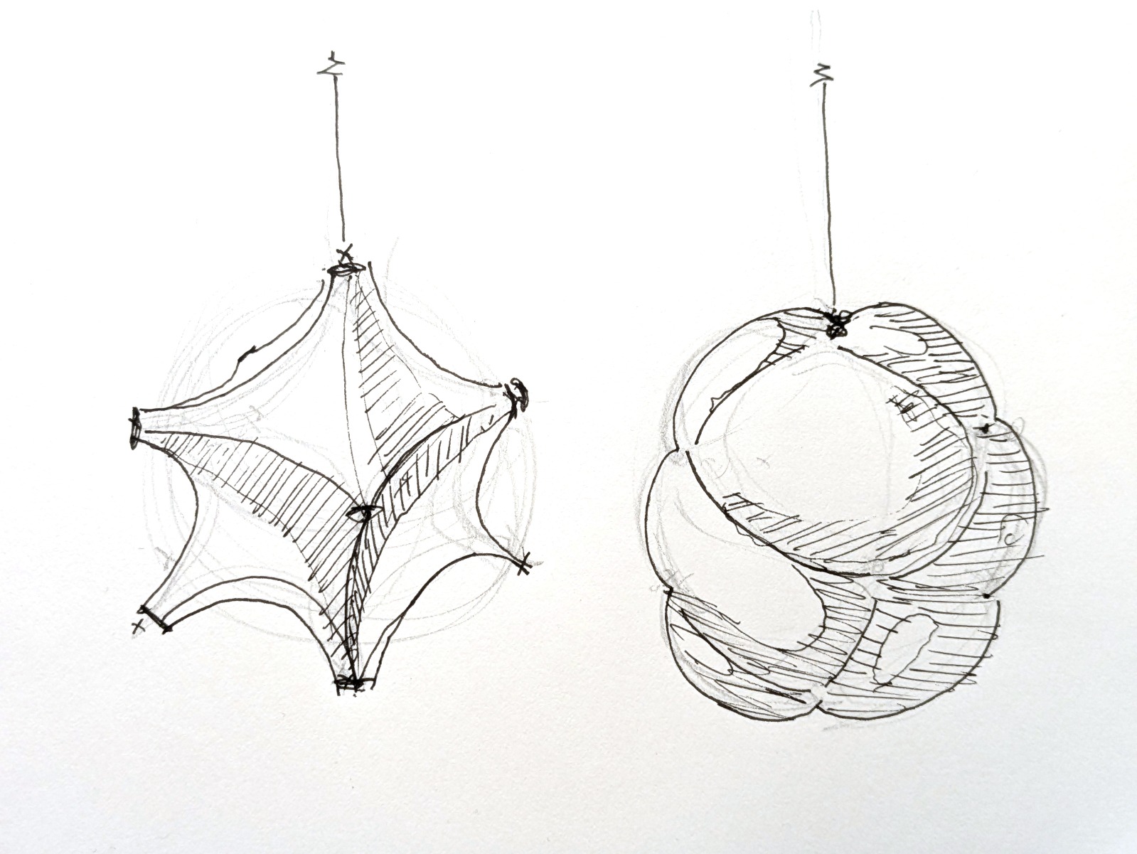
Initial behavior ideas
I have been debating whether to proceed with pneumatics, mechanical actuators, or inflatables. In the end, I think I will drop the inflatables, as I prefer the concave geometries of minimal surfaces over the pillowy qualities of air-filled forms. Moreover, managing closed inflatable cells introduces unnecessary complexity compared to working with an elastic or woven surface.
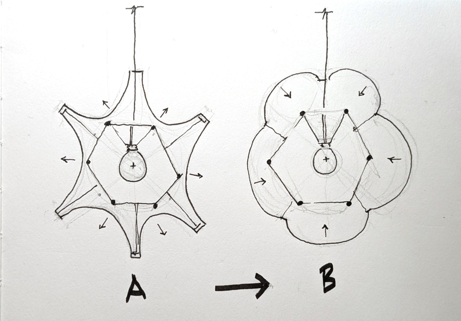
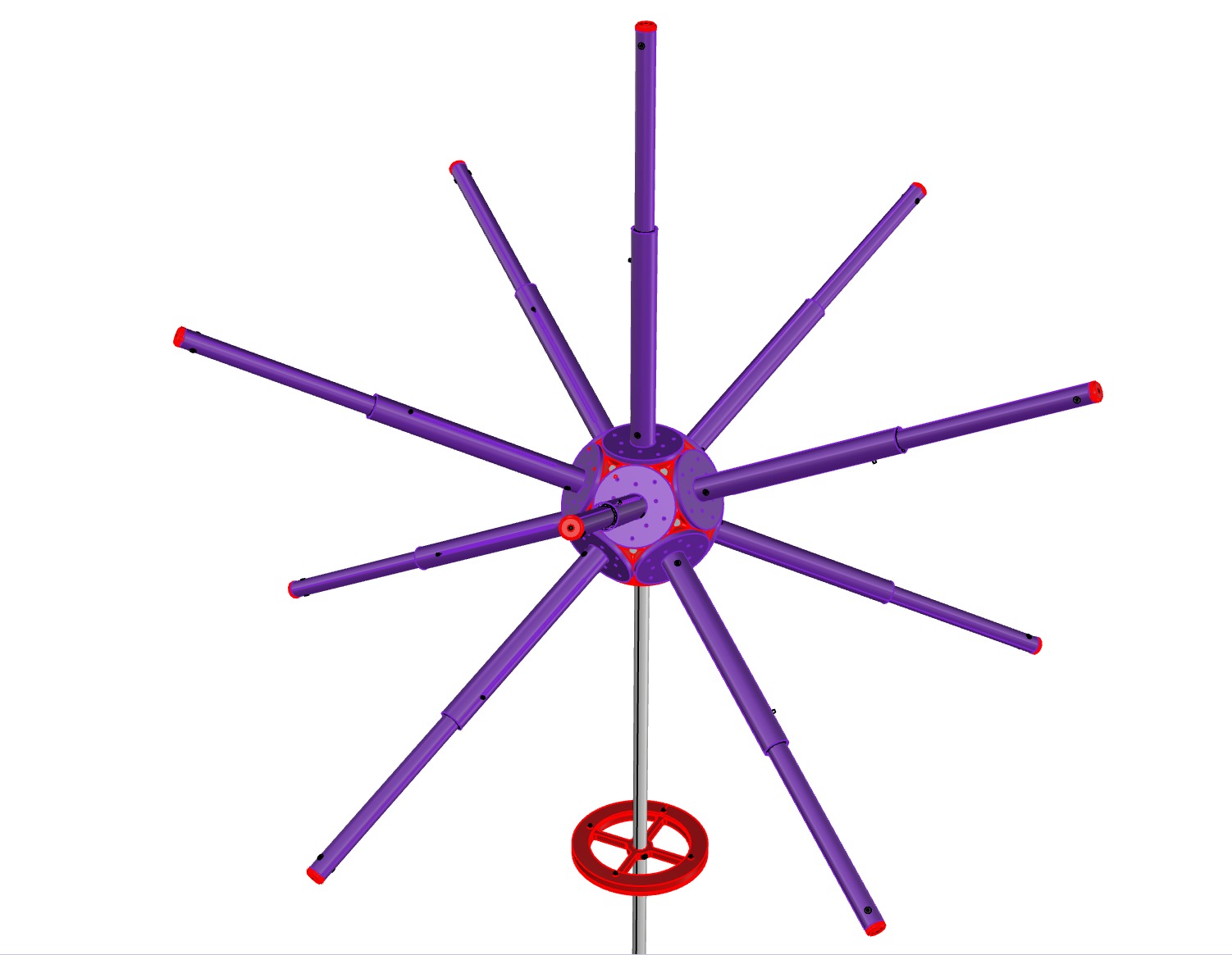
Initial Proposed Design
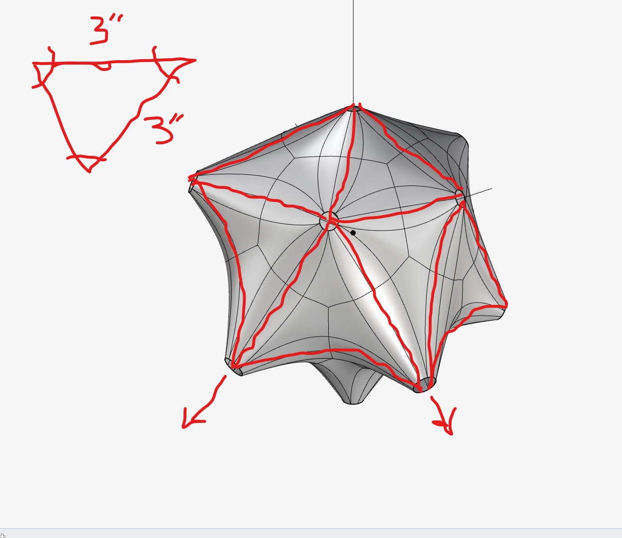
Above I'm testing different forms as a base condition wherein all compressive elements are fully in their retracted condition. For the formal implications of what the membrane will look like due to extended compressive arms, I would have to rely on simulation, as follows.
Material Simulation and Animation
What does it look like? Its tough to tell just by imagining it, and even tougher to predict the results in 3D. Using Kangaroo, a physics engine plug-in for Grasshopper (which itself is a plug-in for Rhino), I can simulate a stretchy skin. I had to set up the parametric definitions to run the simulation, but now I can both model and animate forms while respecting these constraints.
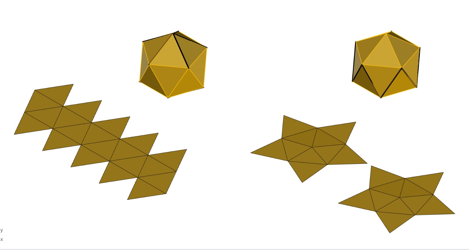
Physics Simulator Script
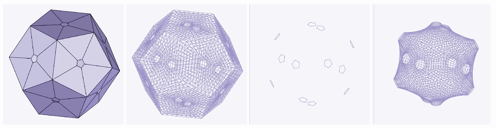
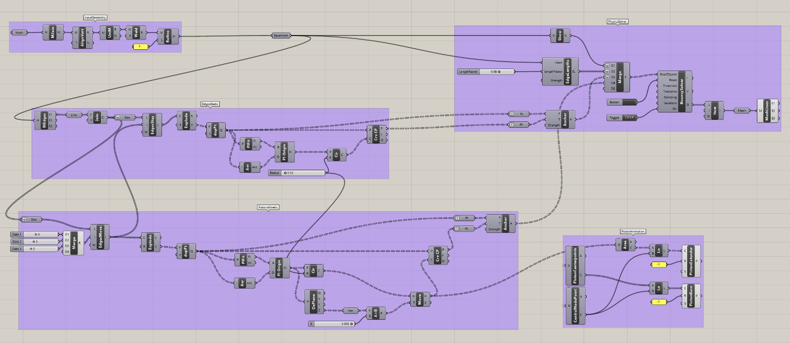
I put together this simulation to test forms and behaviors. In short, it begins with input geometry in this case, an icosahedron. The icosahedron has small offset holes on each of its faces, which become the base mesh for the simulation. You then define which of these holes are static and which are kinetic. This is done by sorting through lists and moving selected points away from the structure's center. Each point has an “input” and a “goal” that the solver works toward in order to generate a real-time parametric simulation. All of this data is fed into the Kangaroo solver, and I am displaying its resulting mesh.
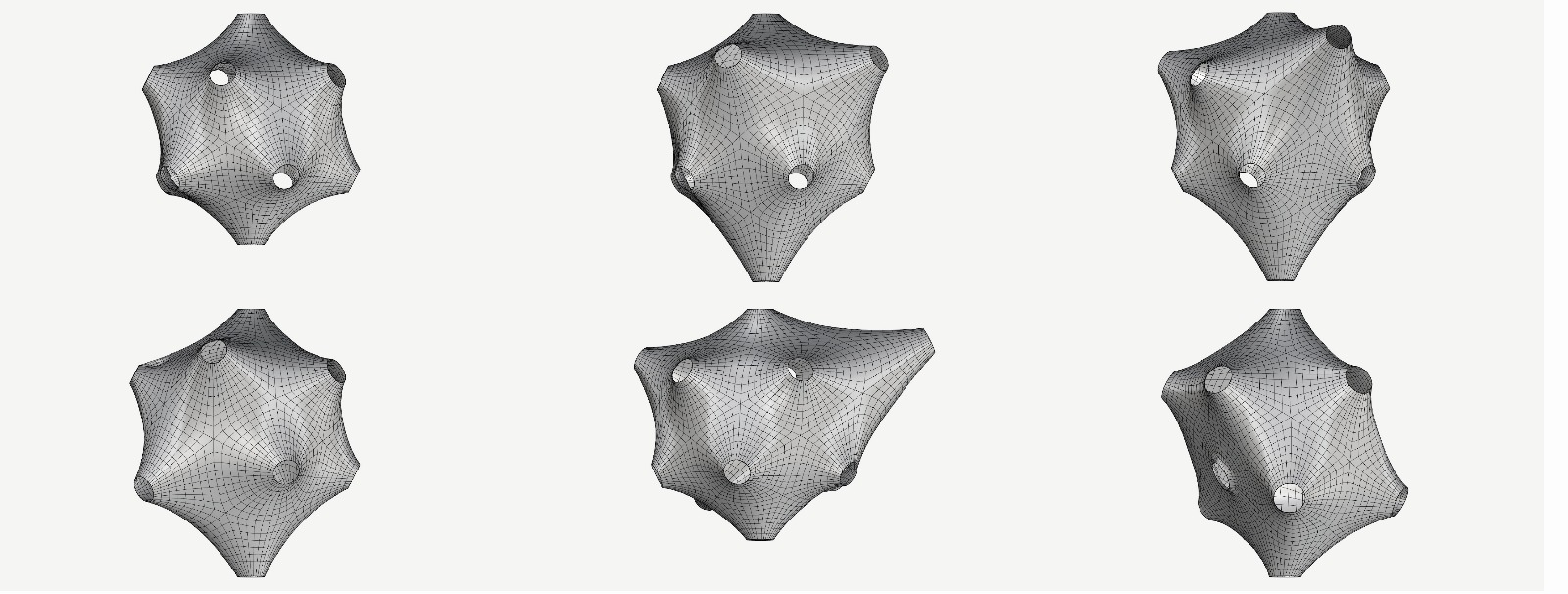
Initial Simulation: Skin
Initial Simulation: Mechanics
Proof of concept of kinetic elements. I think it would be interesting to start working on "behavior" as in, patterns and sequences affecting the linear actuators. For instance, I might test having each arm on a sin curve, syncopated from each adjacent arm. The amplitude of shaft distance traveled could be related to crowds or proximity of people, for instance. I'll return to this later.
Mechanics Concept
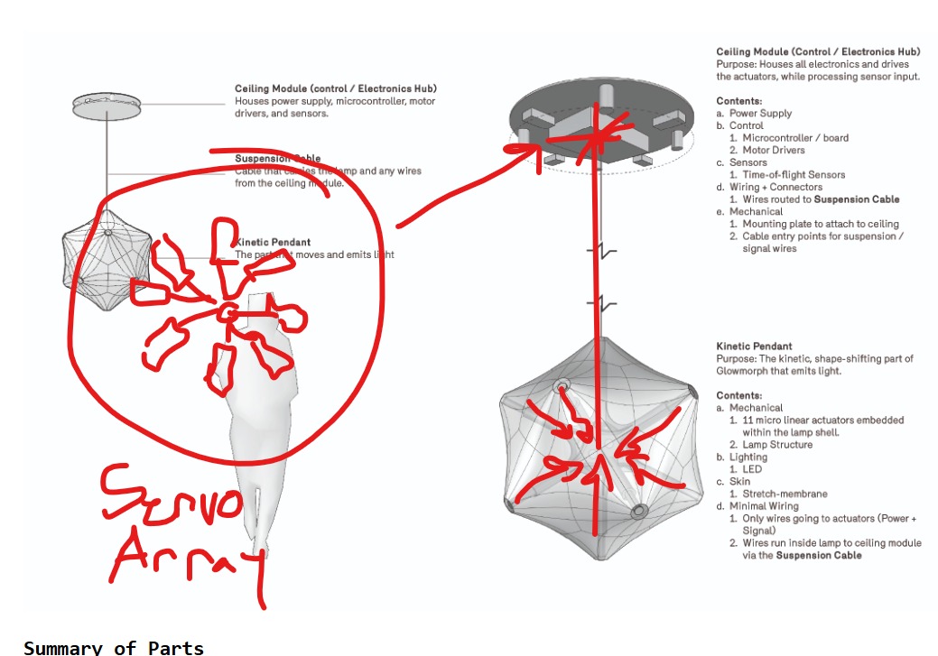
Summary of Parts
-
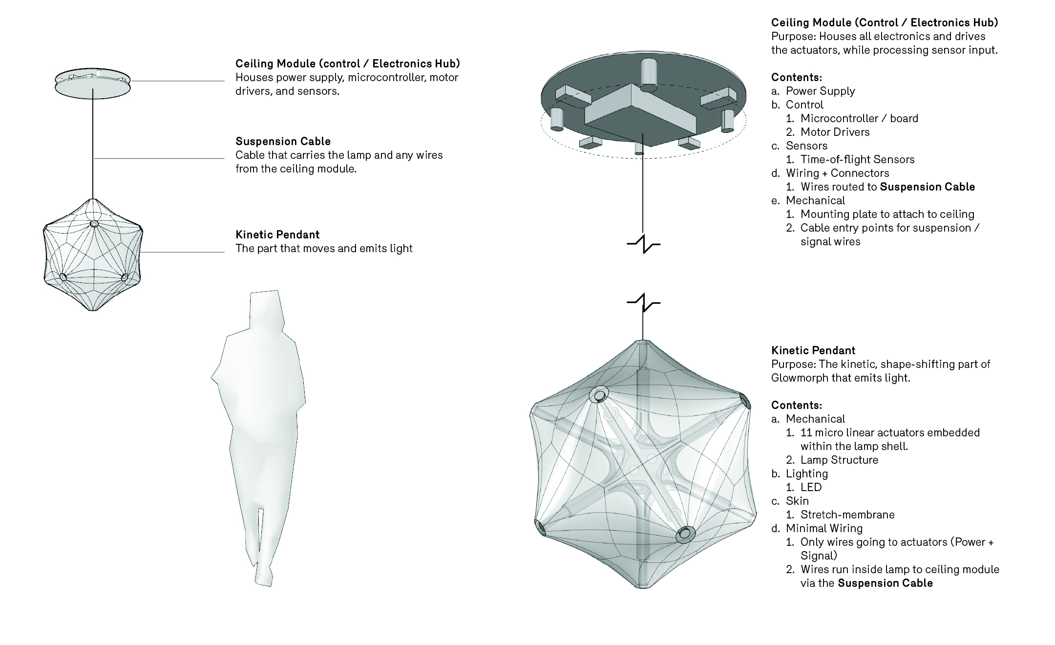
Ceiling Module (Control / Electronics Hub)
Houses the power supply, microcontroller, motor drivers, and sensors. -
Suspension Cable
The cable that supports the lamp and carries all power and signal wires from the ceiling module. -
Kinetic Pendant
The part of the lamp that moves and emits light.
In-Depth Summary of Parts
Ceiling Module (Control / Electronics Hub)
Purpose: Houses all electronics, drives the actuators, and processes sensor input.
Contents:
- Power supply
- Microcontroller / control board
- Motor drivers
- Sensors, including time-of-flight sensors
- Wiring and connectors, routed to the suspension cable
- Mechanical mounting plate for ceiling attachment
- Cable entry points for suspension and signal wires
Kinetic Pendant
Purpose: The shape-shifting, moving part of Glowmorph that emits light.
Contents:
- Mechanical: 11 micro linear actuators embedded within the lamp shell
- Lamp structure / frame
- Lighting: LEDs and diffuser membrane
- Minimal wiring: only power and signal lines for actuators, running through the suspension cable
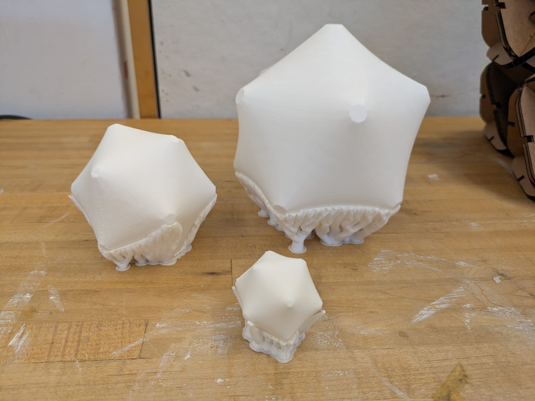
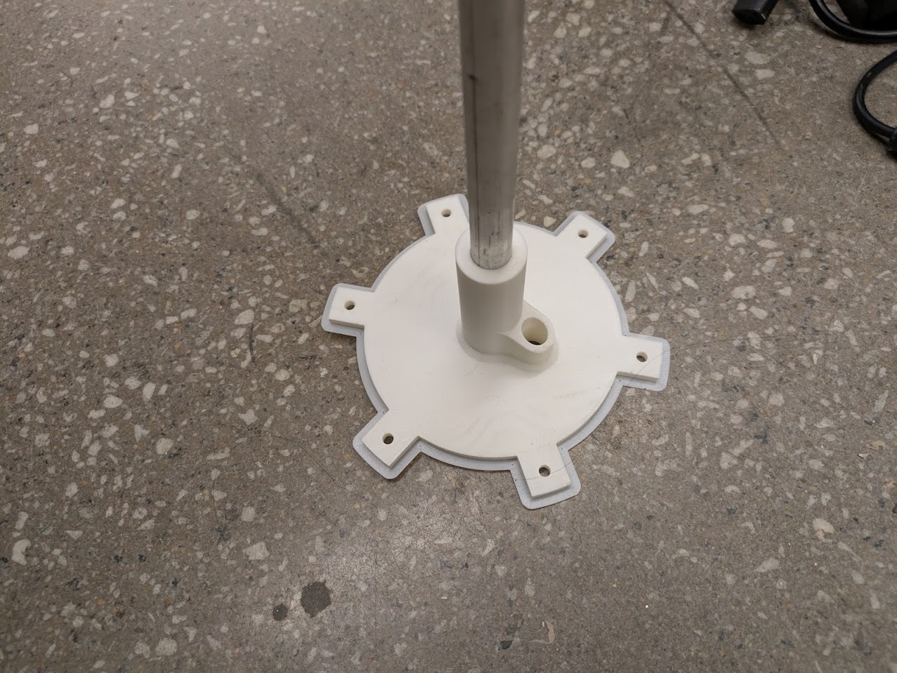
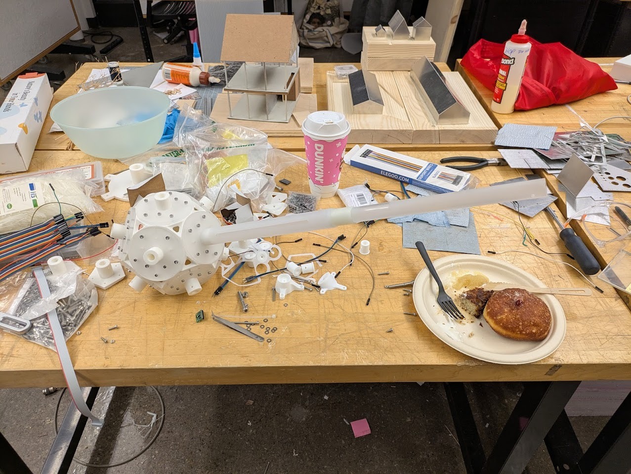
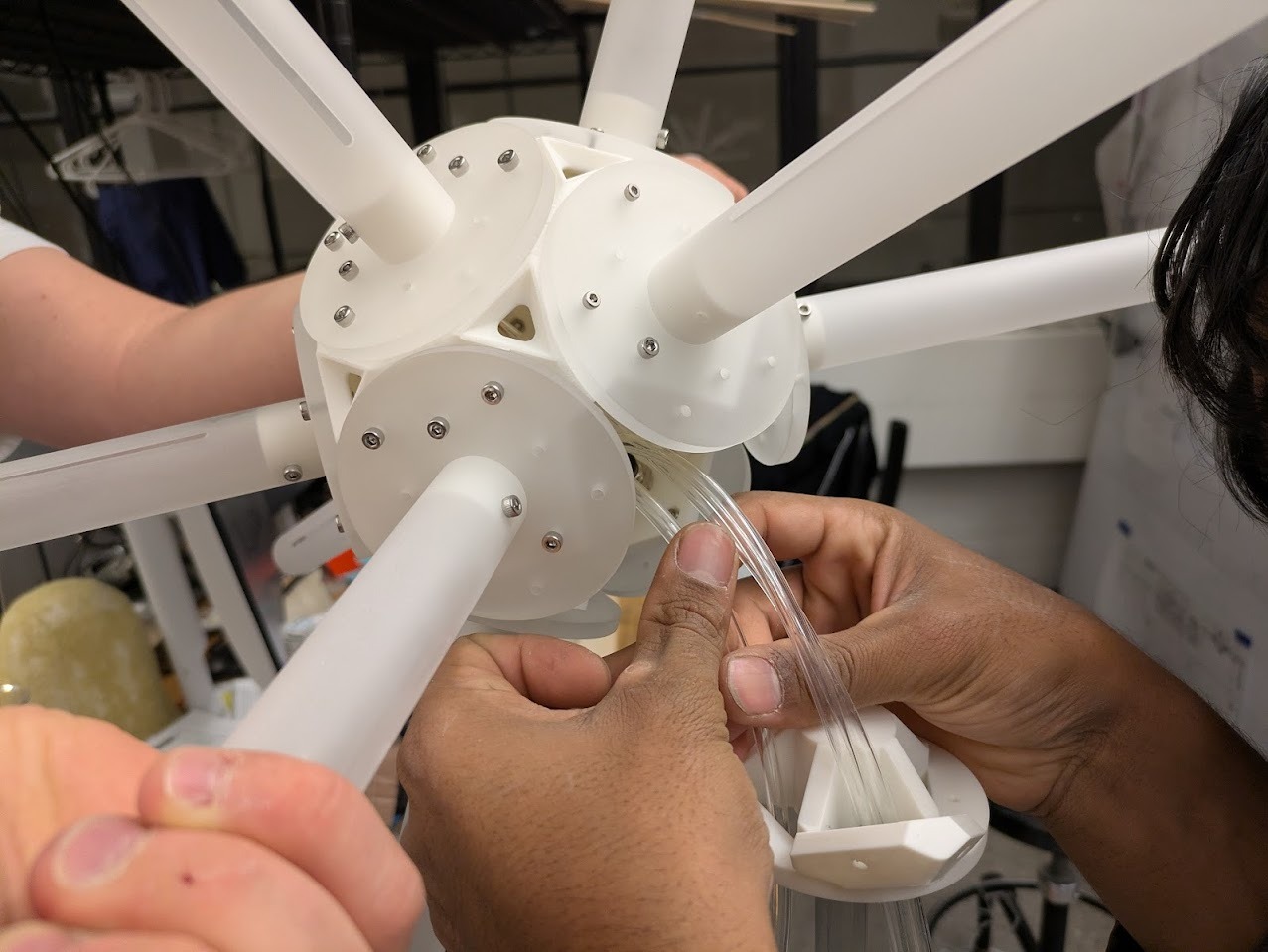
Above: my engineer friend Max Summers suggested I can "make a very smooth telescoping mechanism, you could probably spring load it so it always wants to be extended and use like a string and a pully on a small servo/stepper to wind up and suck in the telescope, that way you dont have like a long screw or something that will affect overall footprint"
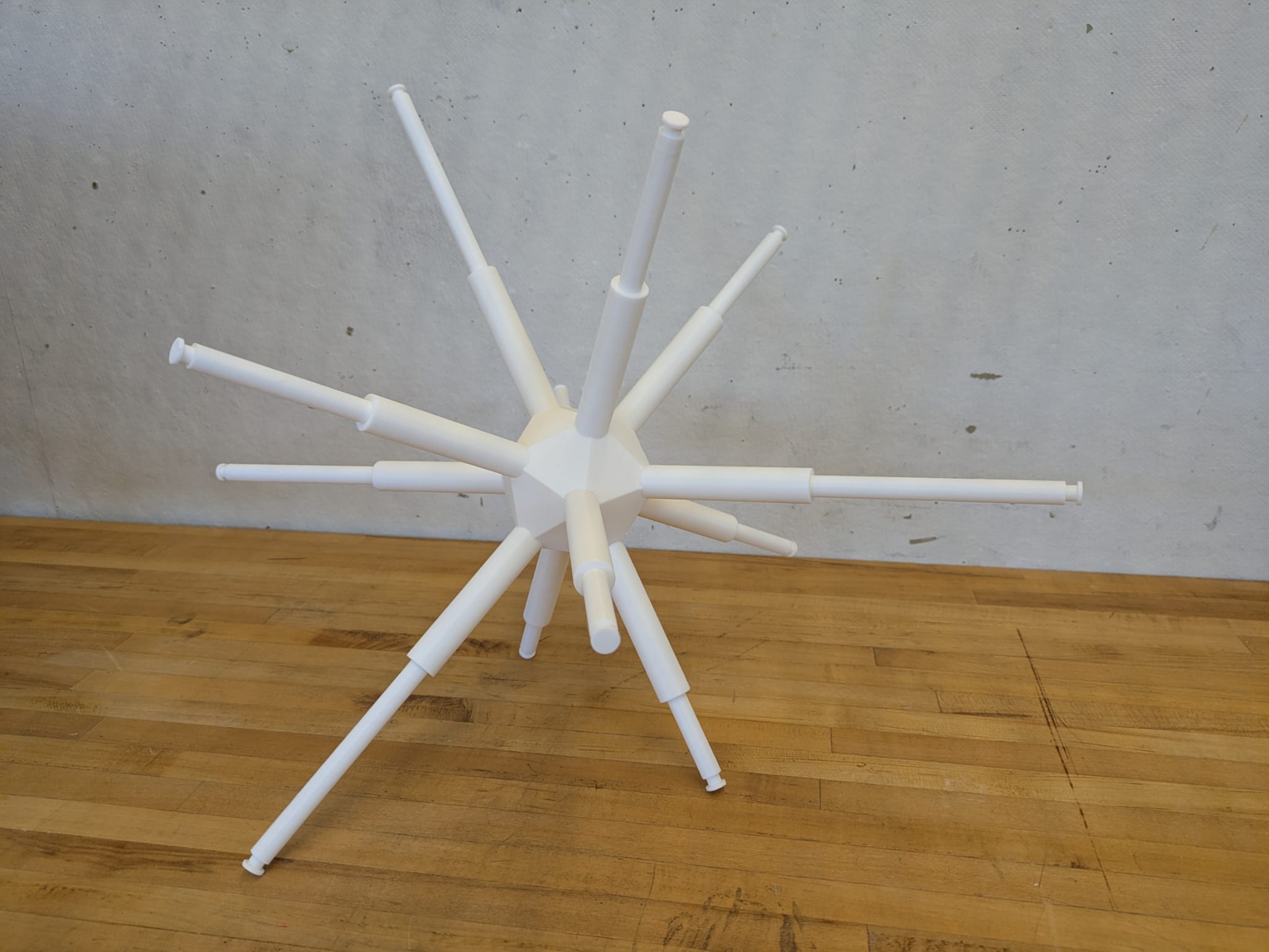
Above is a printed structure with working sliding rods, used to start testing membrane skins.
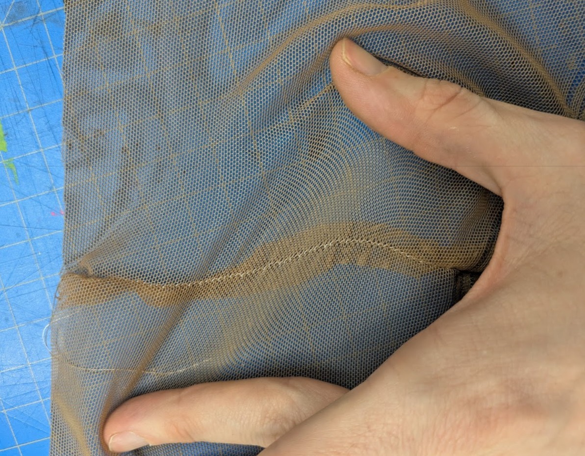
Membrane Skin
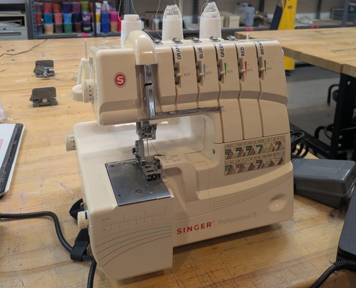
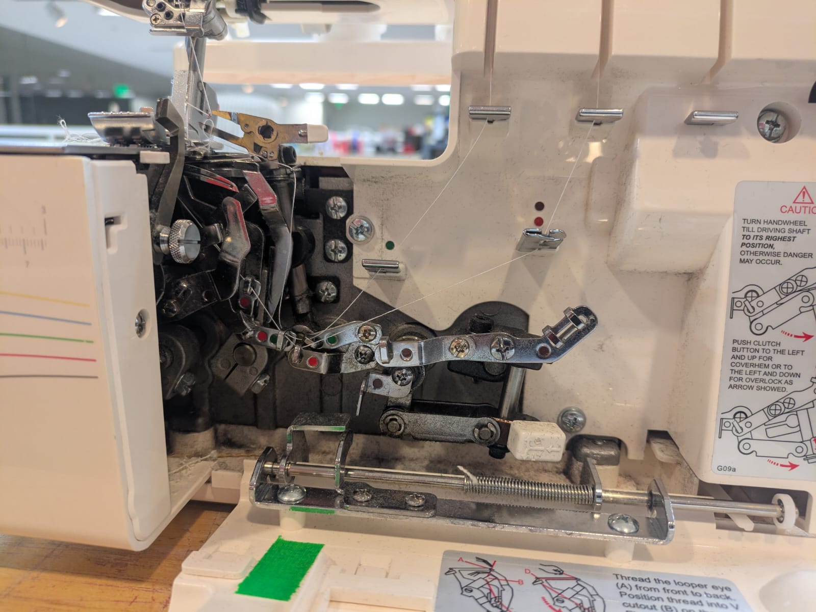
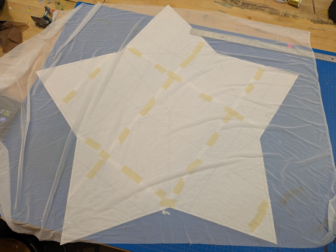
For the 'skin' of Glowmorph, I'm looking for a material that will allow light transmittance and has a strong 4-way stretch. I'm currently testing nylon or performance mesh. In order to join the material, I'm thinking about either tiling a repeated triangular shape, or unrolling the skin as a sort of 'Dymaxion Map'. Regardless of what material I'm using, it's important to get a consistent sewed and cut edge with minimal material being expressed on the interior. Graham help me set up the serger machine which sews and cuts for a very small expressed inner edge and a precise overlocking stitch.

Above I'm referencing the dymaxion map as a potential strategy to unrolling the skin to keep a minimal amount of edges to sew.
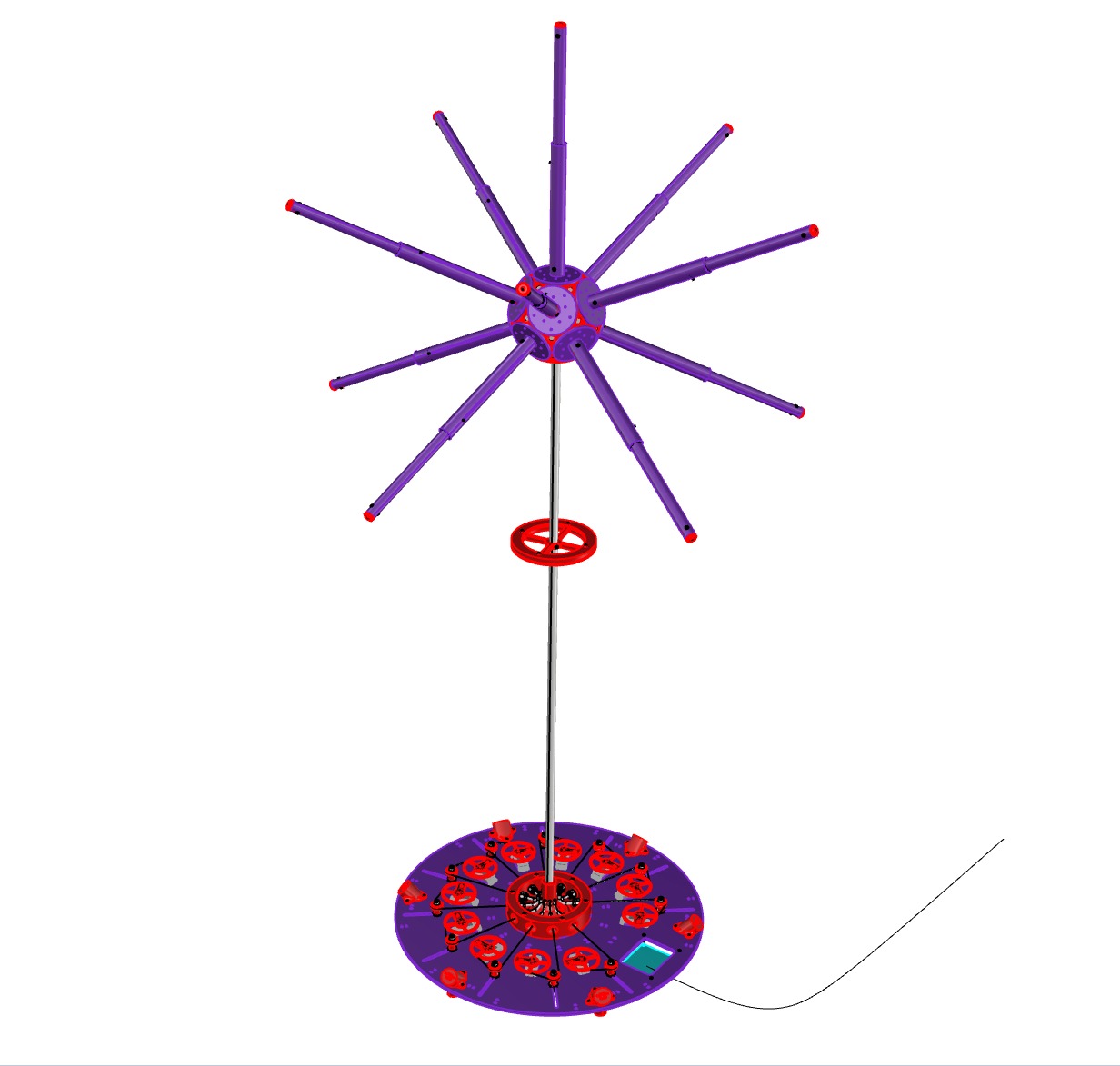
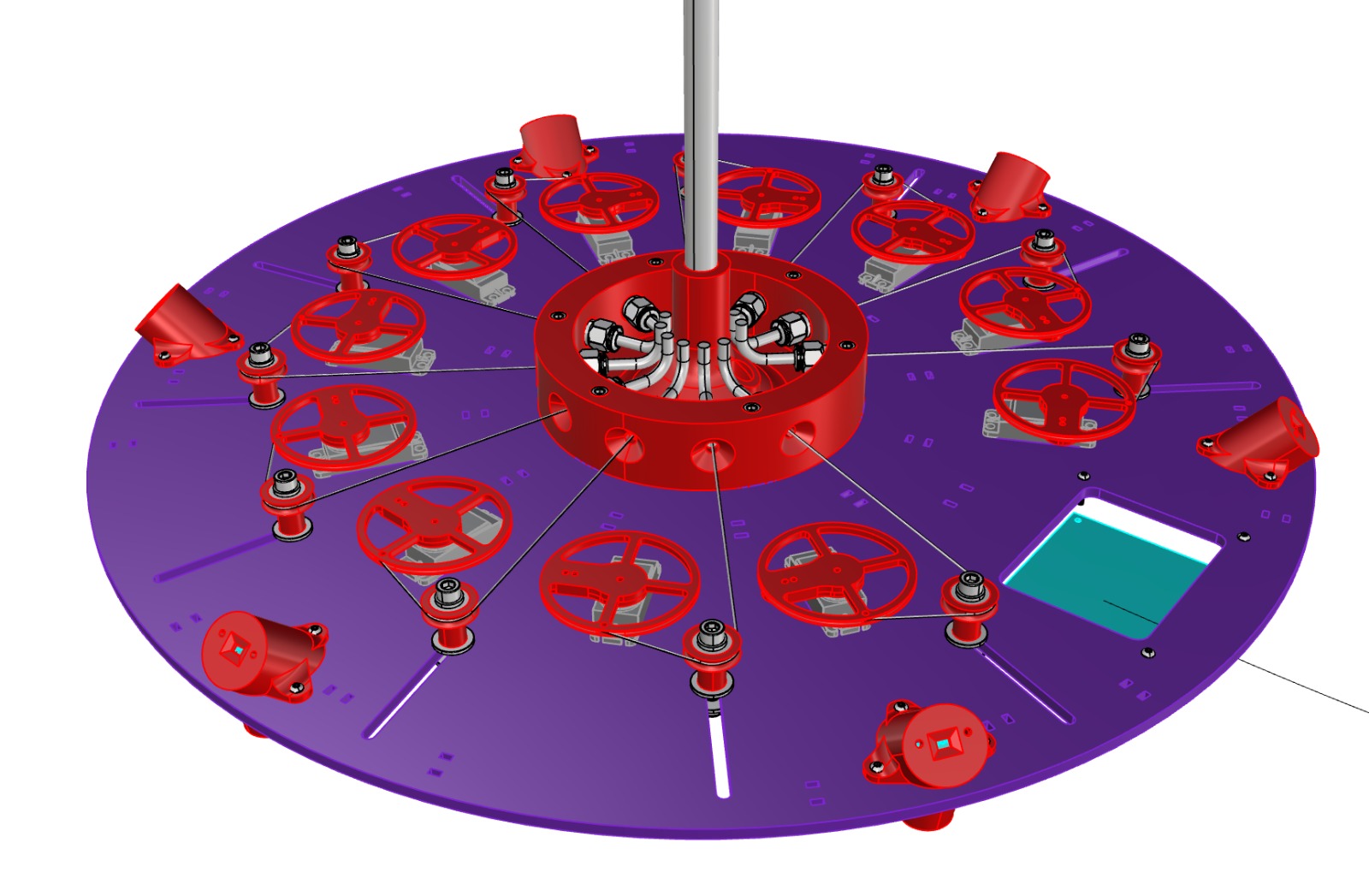
Piston Arms
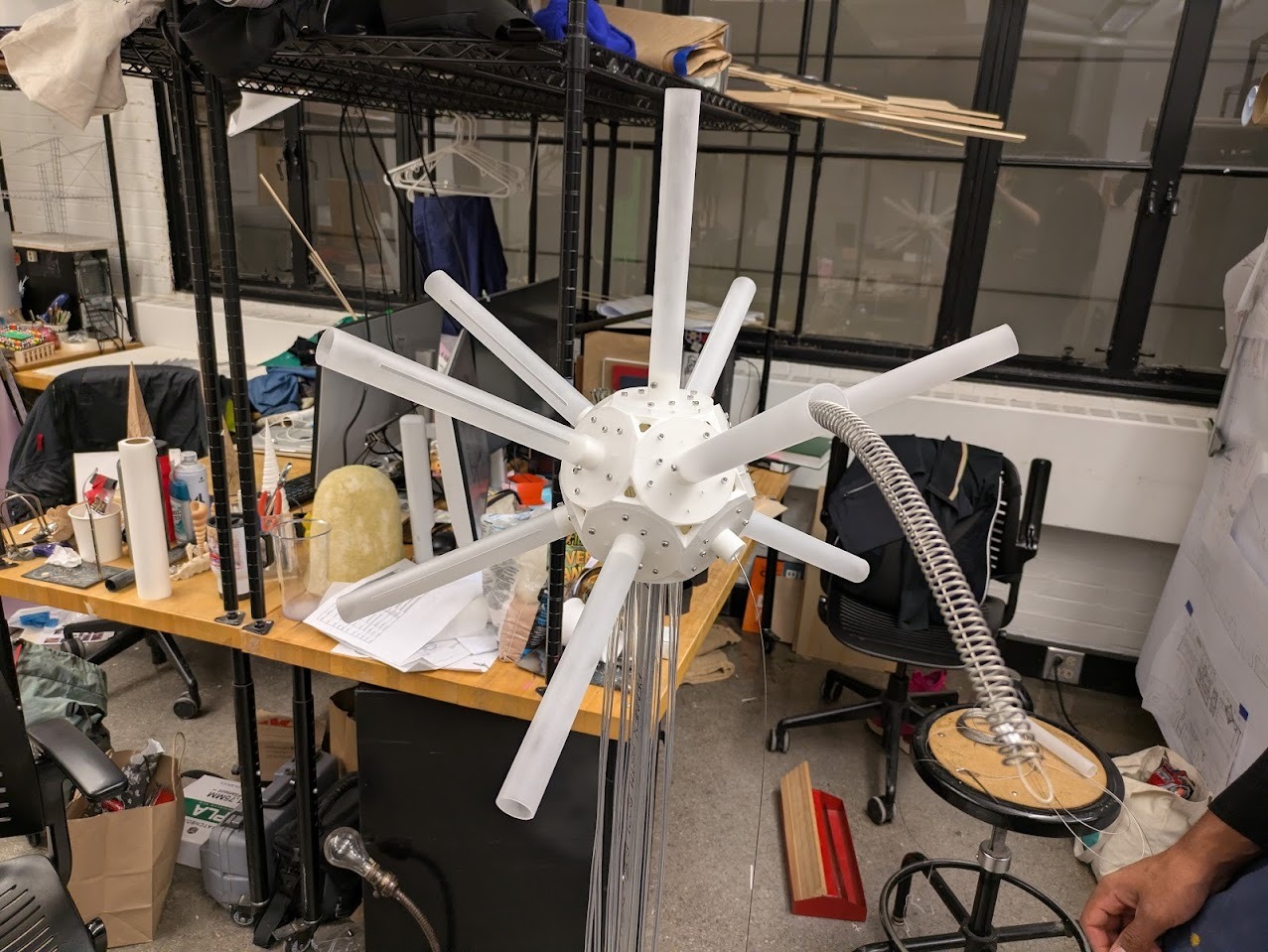
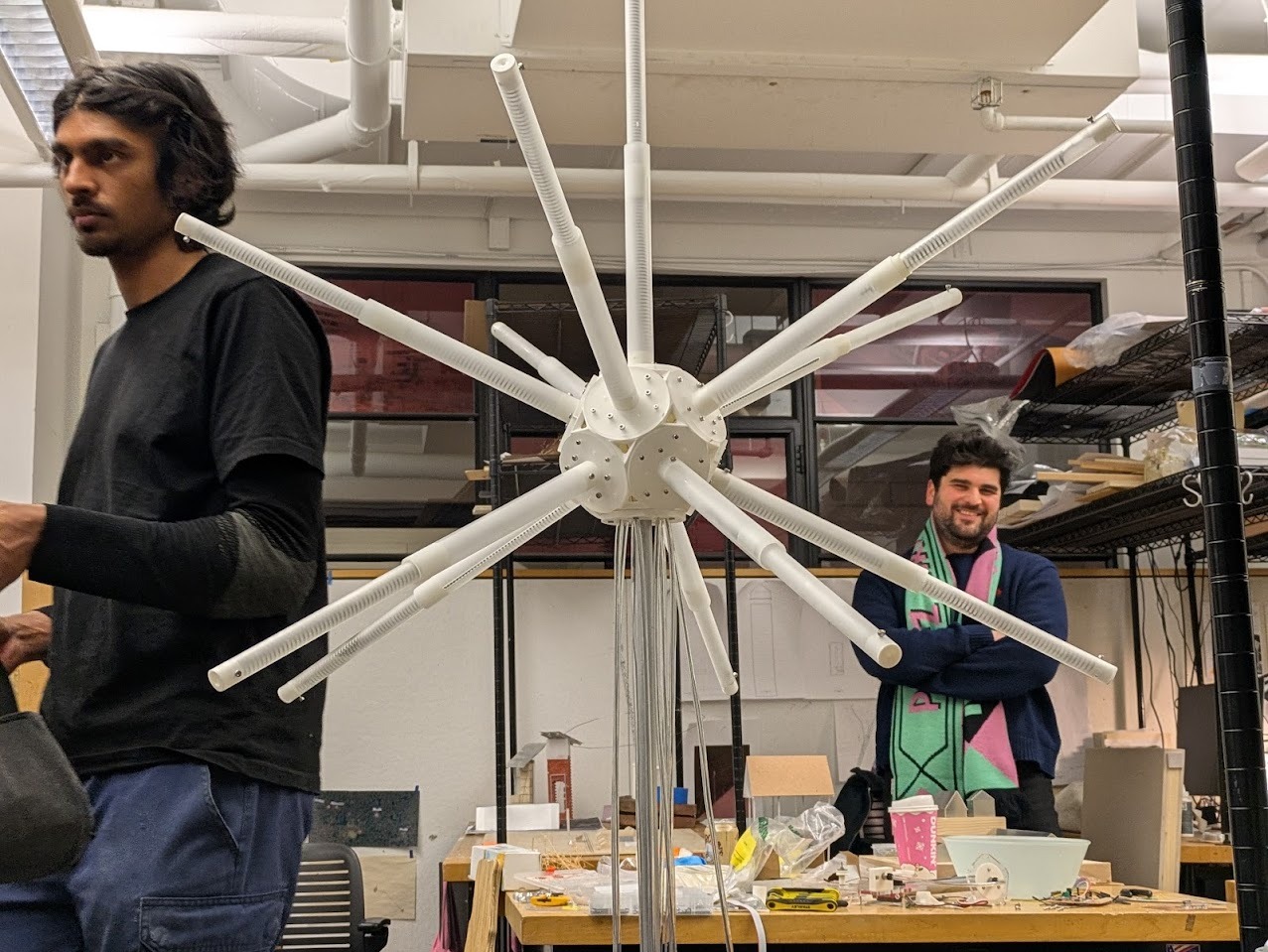
How it boils down is that the kinetic lamp is essentially a puppet, where all the motors are hidden in the base plate, and cables are routed through to actuate it's arms. This is done to save space in the lamp and have it as light as possible, with no chunky inner node.
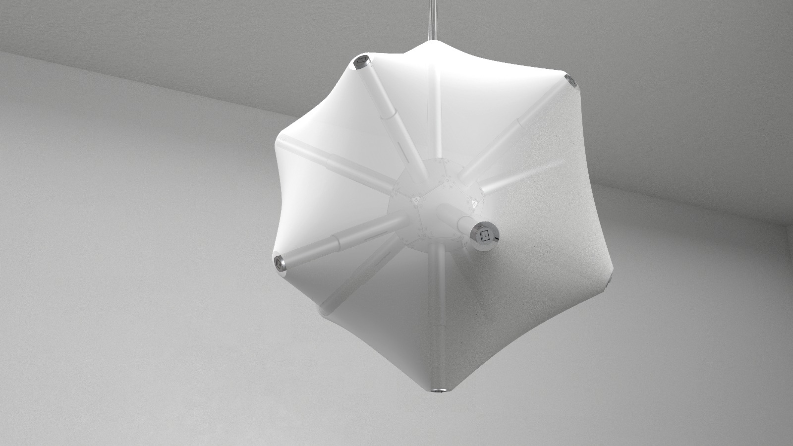
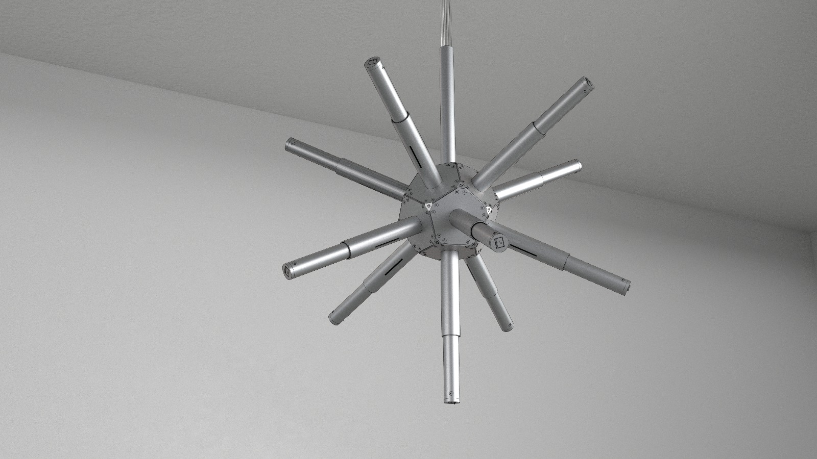
The latest design above. Please note that the skin is hidden in this view so that we can focus on the mechanics.

This week I will be trying to get one of these arms working. Not an unreasonable goal I think, but let's see.
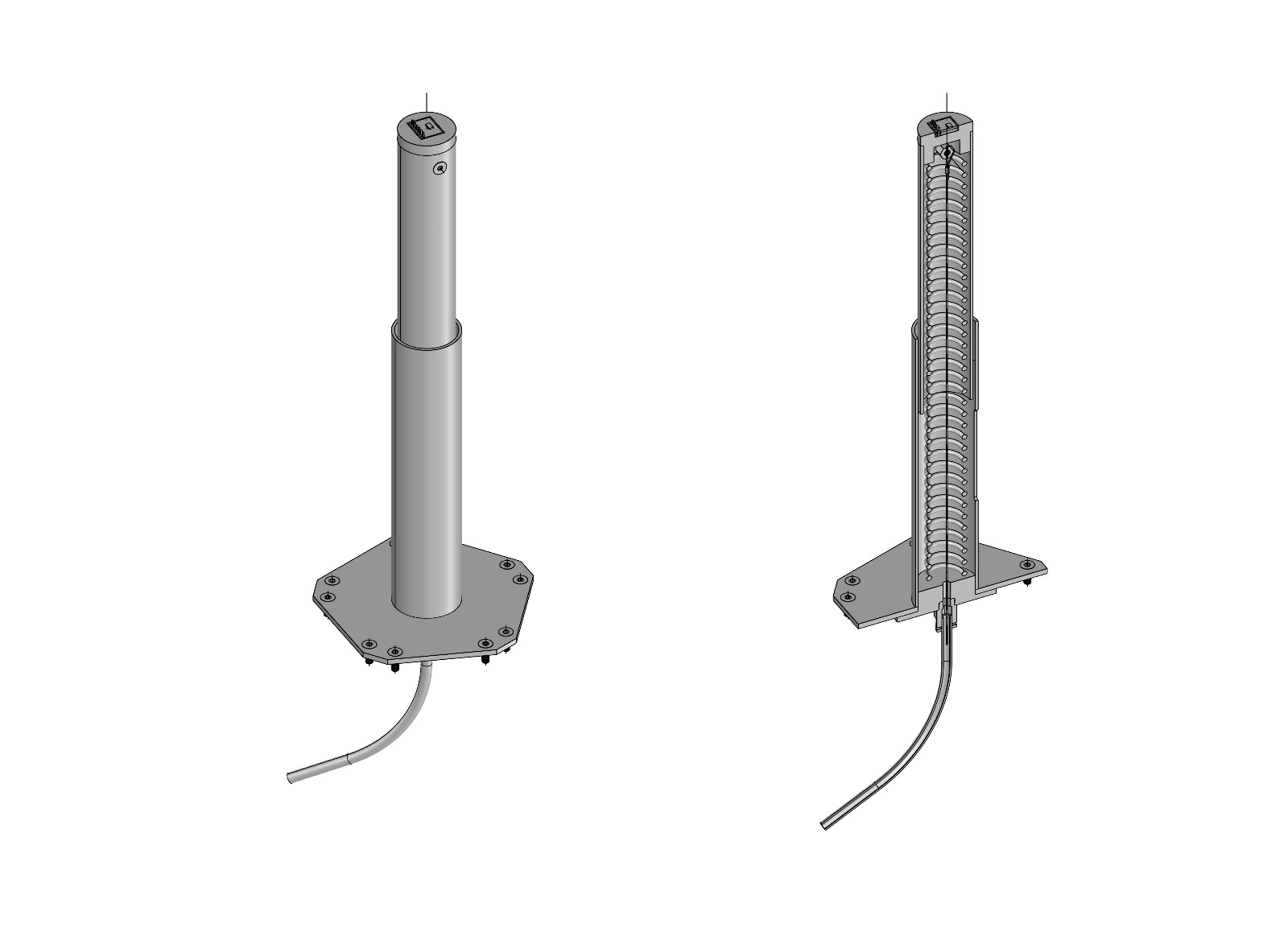
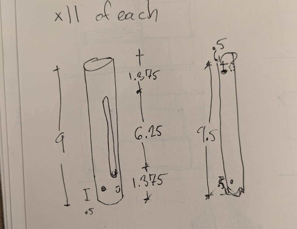
Here are one of the 11 isolated kinetic arms with cutaway

This is how I'm proposing to build one of the 11 kinetic arms. Much still to figure out, but broad strokes are there.
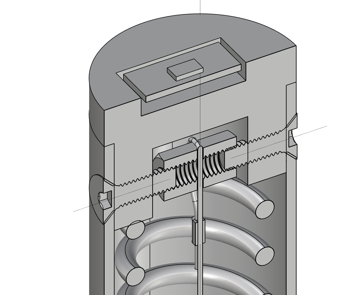
Cutaway of the piston head.
Ecosystem Logic
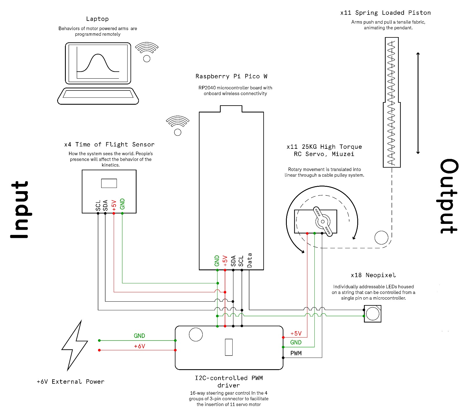
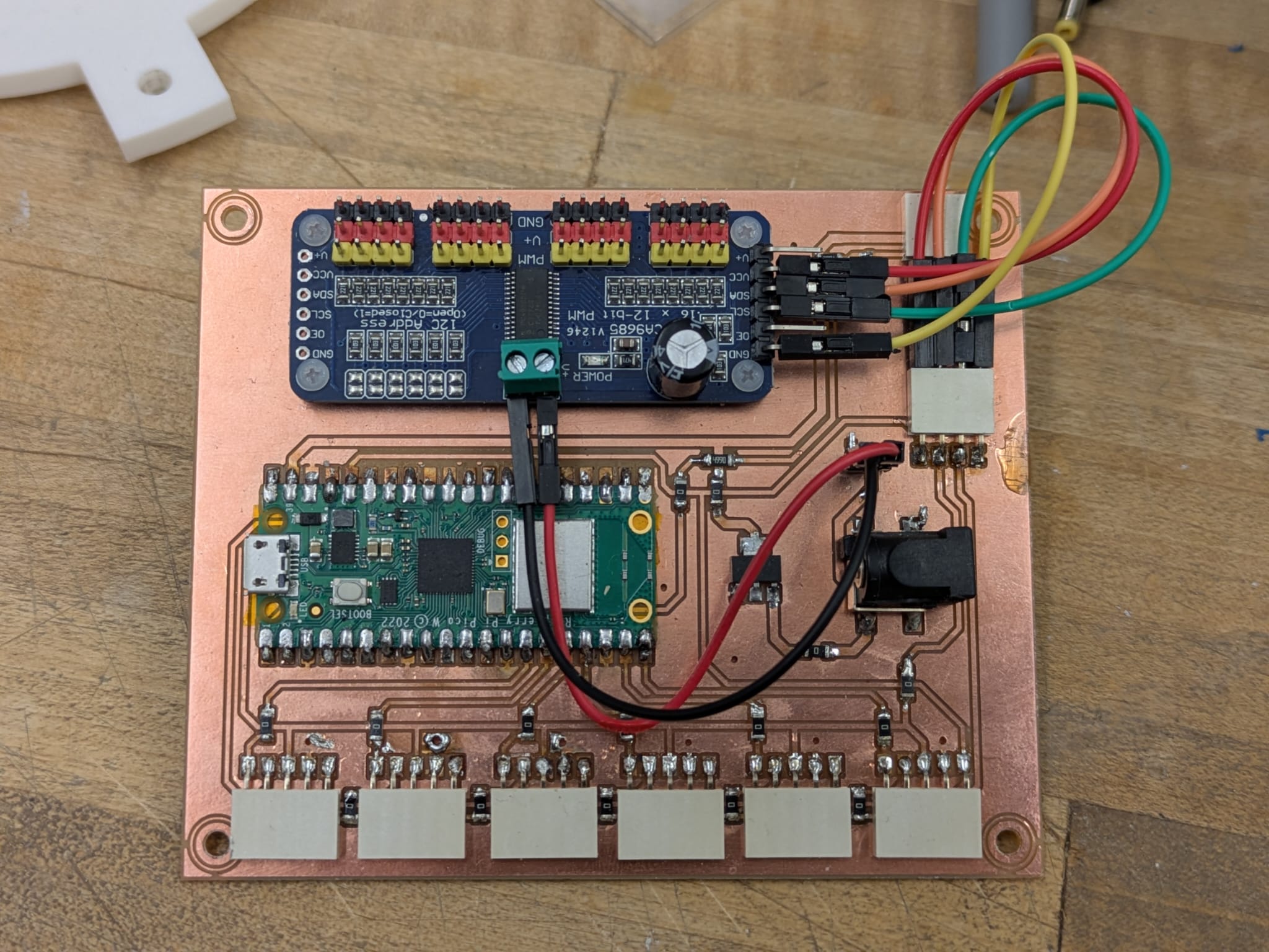
We were asked to put together a system diagram for our project. This was my swing ata it. Glowmorph isnt a single object—it’s a small ecosystem of boards, voltages, and control signals that all need to play nicely together. This diagram shows the choreography b/w the XIAO microcontroller, the PCA9685 servo driver, and the 6V high-torque servo that drives the lamp’s piston movement.
The core idea is simple: keep logic and power separate, but let everything share a common ground. The XIAO provides clean 5V logic power to the PCA’s VCC, while the servo receives its own dedicated 6V supply through the PCA’s V+ terminal. A large electrolytic capacitor on the servo rail smooths out current spikes from any of the 11 DS3218MG sudden load changes, preventing brownouts and keeping the system stable.
With this setup, the PCA9685 becomes the electrical “hub” for Glowmorph: it isolates the heavy lifting of the servo from the delicate logic of the microcontroller, and should give me predictable, smooth 270° motion for the cable-driven piston.
Final Build
Final 3D model overview
Final 3D model Light Module
Final 3D model base
Final Inventory
Electronics
- 1 × Raspberry Pi Pico W (main microcontroller)
- 1 × PCA9685 16-channel PWM Servo Driver (I2C)
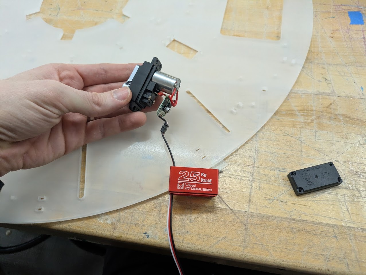
- 11 × High-torque 270° servo motors (DS3218MG class)
- 6 × Time-of-Flight distance sensors (VL53L1X)
- 20 × NeoPixel LEDs (planned / partially tested)
- 1 × Custom milled PCB (logic, power distribution, headers)
- Electrolytic capacitors (servo rail smoothing)
- Resistors, headers, pin sockets, jumpers
Power
- 1 × 6V DC power supply (high-current, servo rail)
- 5V logic regulation (onboard / via microcontroller)
- Barrel jack connector
- Common ground shared between logic and servo power
Mechanical Components
- 11 × Acrylic piston arms (machined)
- Clear acrylic tubing (piston bodies)
- Laser-cut and CNC-machined acrylic base plates
- Aluminum central support rod
- Steel cable (actuation lines)
- Compression springs (tuned per piston)
- Pulley wheels and jockey wheels
- Ball bearings (free-spinning cable redirection)
- Partially threaded bolts (bearing axles)
- M3 / M4 fasteners, washers, spacers
Tube & Cable Routing
- PTFE tubing (low-friction cable routing)
- Push-to-connect pneumatic fittings (PTFE connectors)
- Zip ties (wire management and strain relief)
Fabrication & Finishing
- Clear acrylic sheet
- Sandblasted (frosted) acrylic panels
- 3D-printed structural and spacer components
Membrane Skin (Planned / Partial)
- 4-way stretch nylon / performance mesh fabric
- Polyester thread (zig-zag stitching)
- Tear-away stabilizer
Tools & Processes Used
- Wet saw (acrylic cutting)
- Vertical mill (slots and holes)
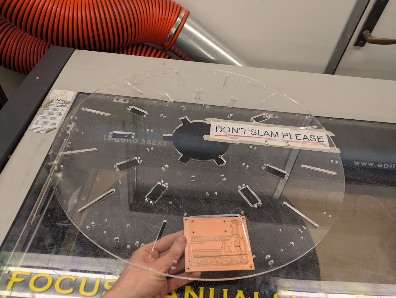
- Laser cutter (acrylic parts)
- PCB mill
- Soldering station
- Sewing machine and serger
- Sandblaster (acrylic frosting)
Manufacturing the Piston Arms
The piston arms were fabricated from clear acrylic tubing. I began by cutting the tubes to length using the wet saw in the Deep Metal Shop. The blade RPM was set very high, as recommended for plastics, and the feed rate was kept slow to minimize chipping and cracking.
The next step was machining circular holes and longitudinal slots into each tube. With Varun’s help, I set up the mill and used an edge finder to establish a reliable zero relative to the tube. Once referenced, I swapped the tool for an adapter holding an end mill intended for plastics.
Acrylic prefers spindle speeds well above what the mill can provide. I set the spindle to its maximum of 5,000 RPM and compensated with shallow passes. The material proved far more fragile than expected, so particular care was taken not to crush the tubes when clamping.


Despite a few miscuts, the resulting parts were accurate enough for assembly and testing.
Wire Management
To avoid a dense bundle of wires beneath the motor board, I organized the system radially. Servo wiring was treated as central infrastructure, while sensor wiring was routed peripherally. Zip ties were used deliberately to make the system legible, serviceable, and transportable.
Membrane Skin
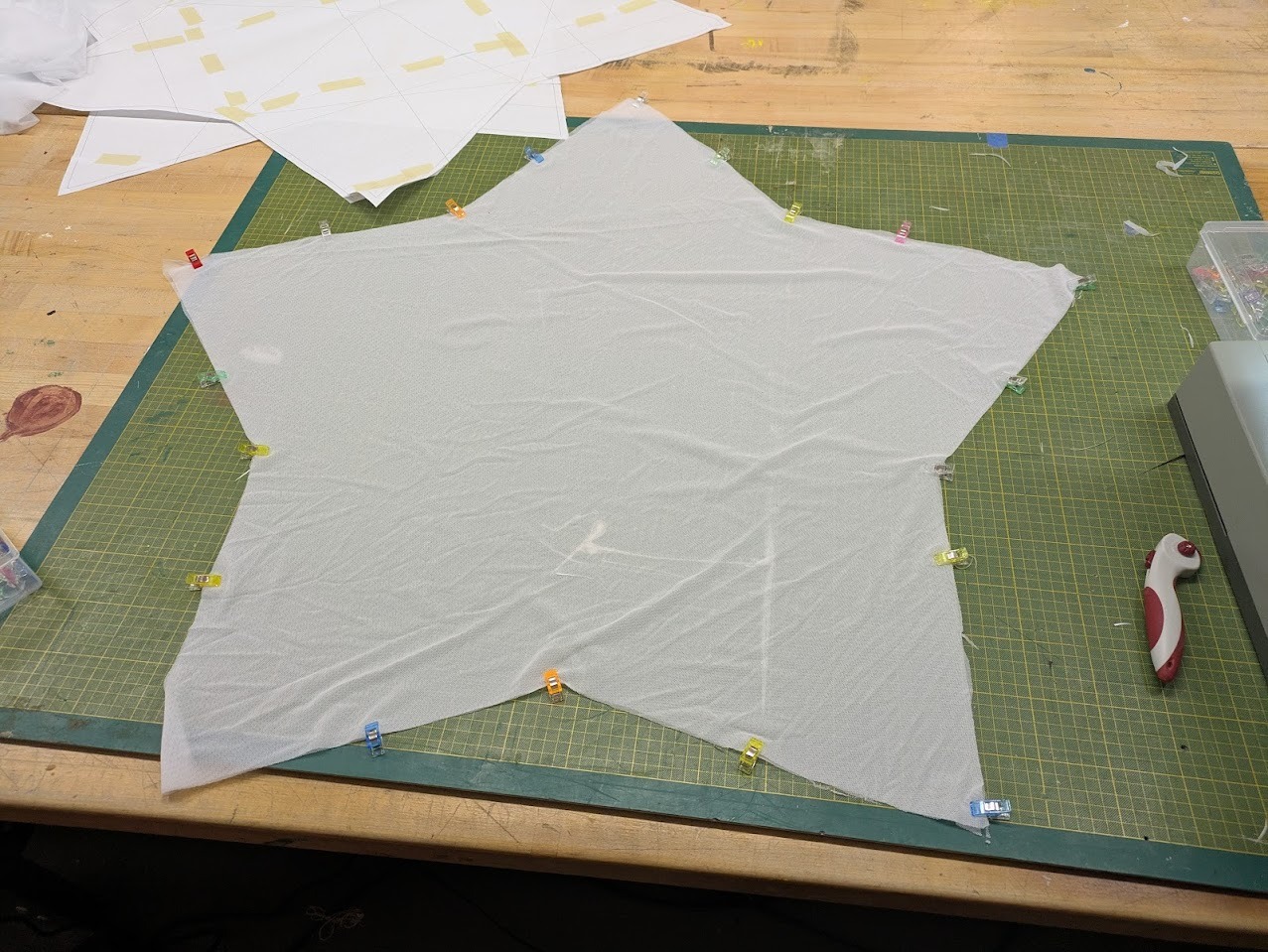
Two approaches were considered for the membrane skin. The first involved a Dymaxion-style unrolling of the icosahedron into triangular facets. The second relied on the elasticity of a 4-way stretch fabric to absorb geometric imprecision.
I chose the second approach. Like a baseball rather than a soccer ball, the skin is composed of two primary sewn halves. This dramatically simplified fabrication while remaining visually consistent with the form.
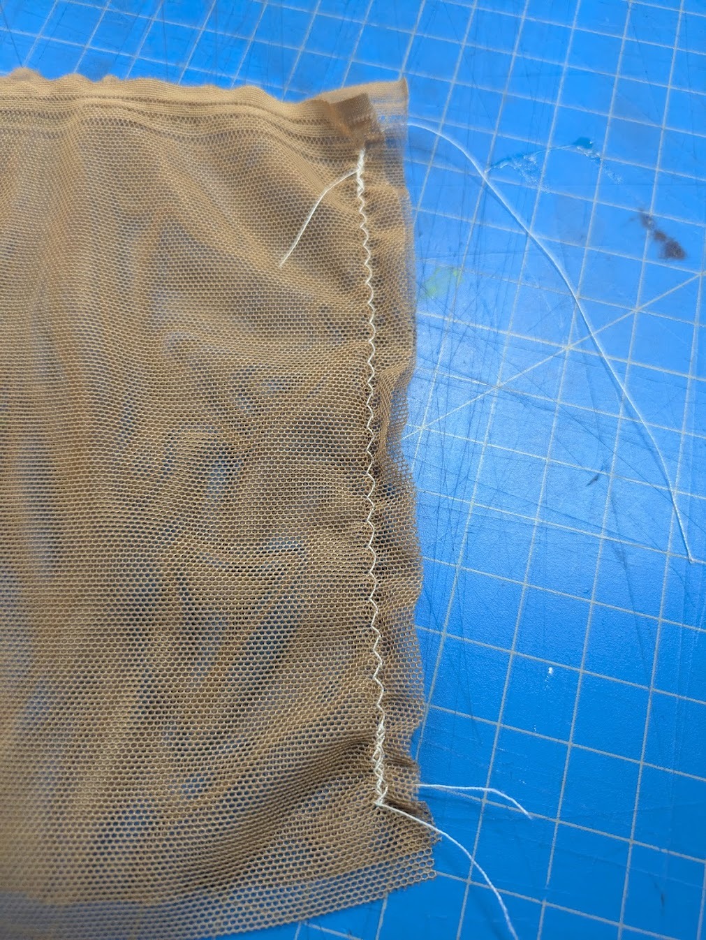
Testing different stitches for elasticity allowance.
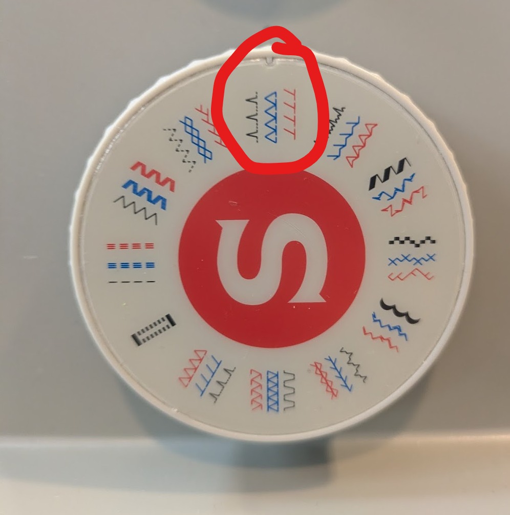
Testing indicated that a zig-zag stitch with a non-stretch polyester thread provided the best balance between elasticity and structural stability.
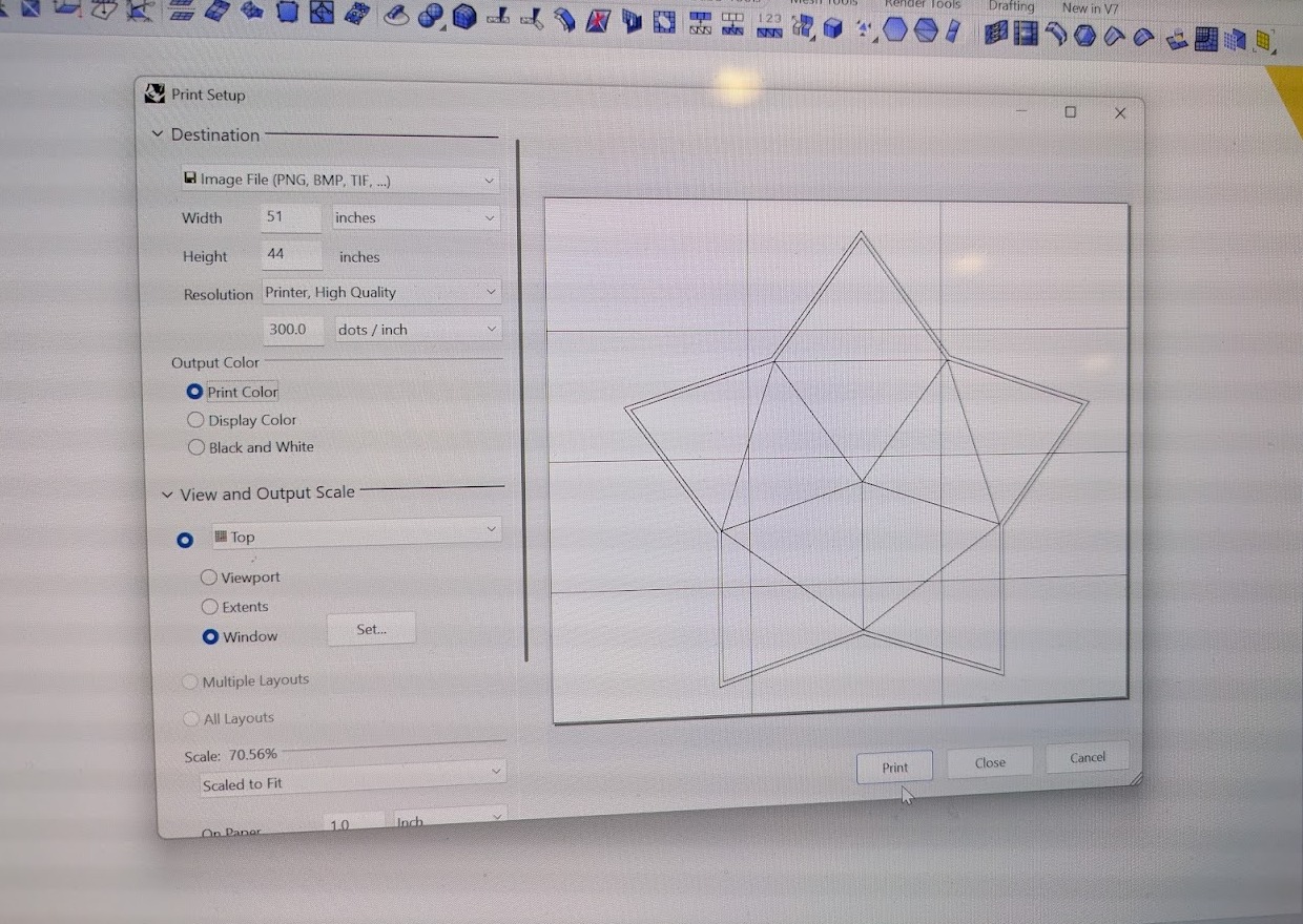
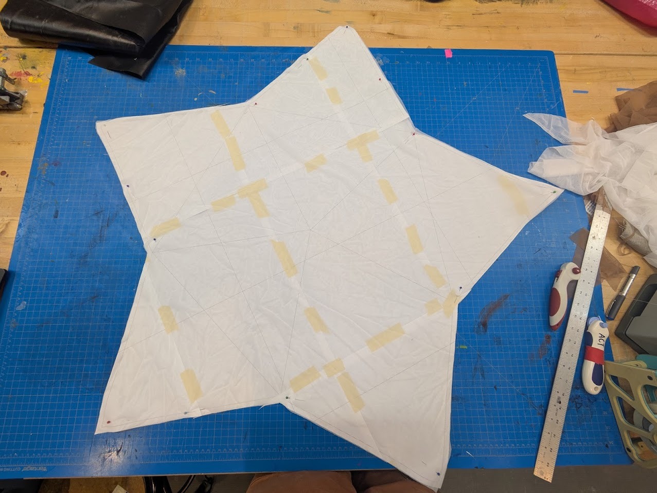
Sewing patterns were printed on 11×17 paper, tiled, taped, and transferred to fabric. The panels were cut with a rotary cutter and sewn together, leaving one seam open for hand-stitching after final assembly.
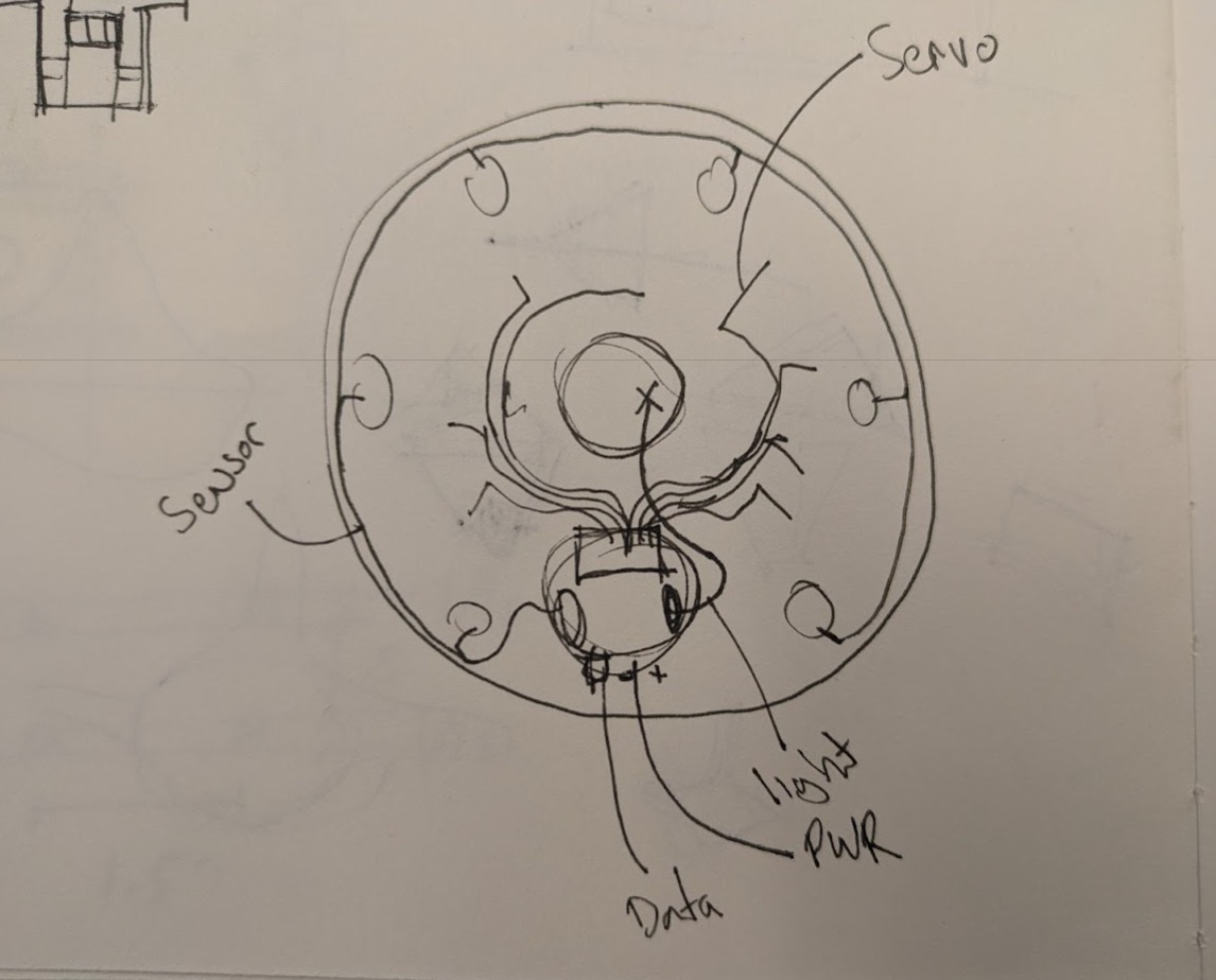
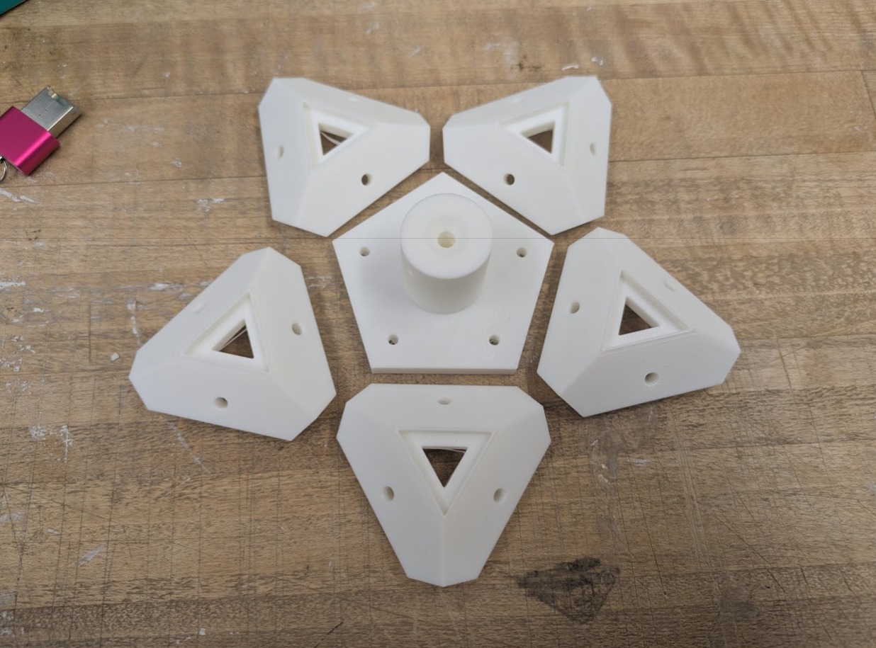
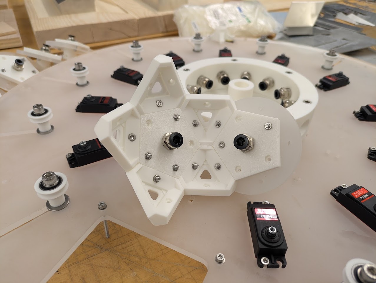
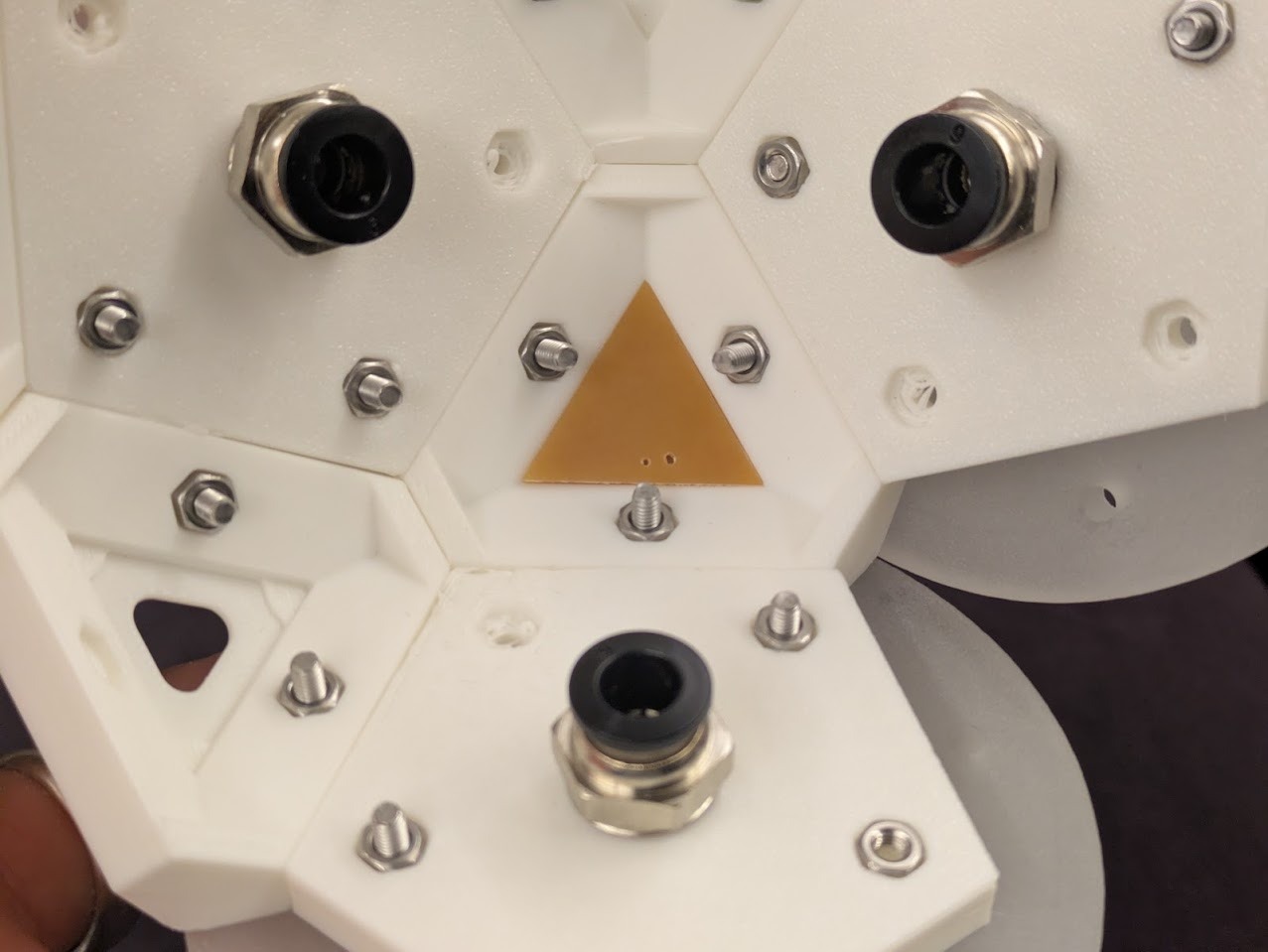
Node Design
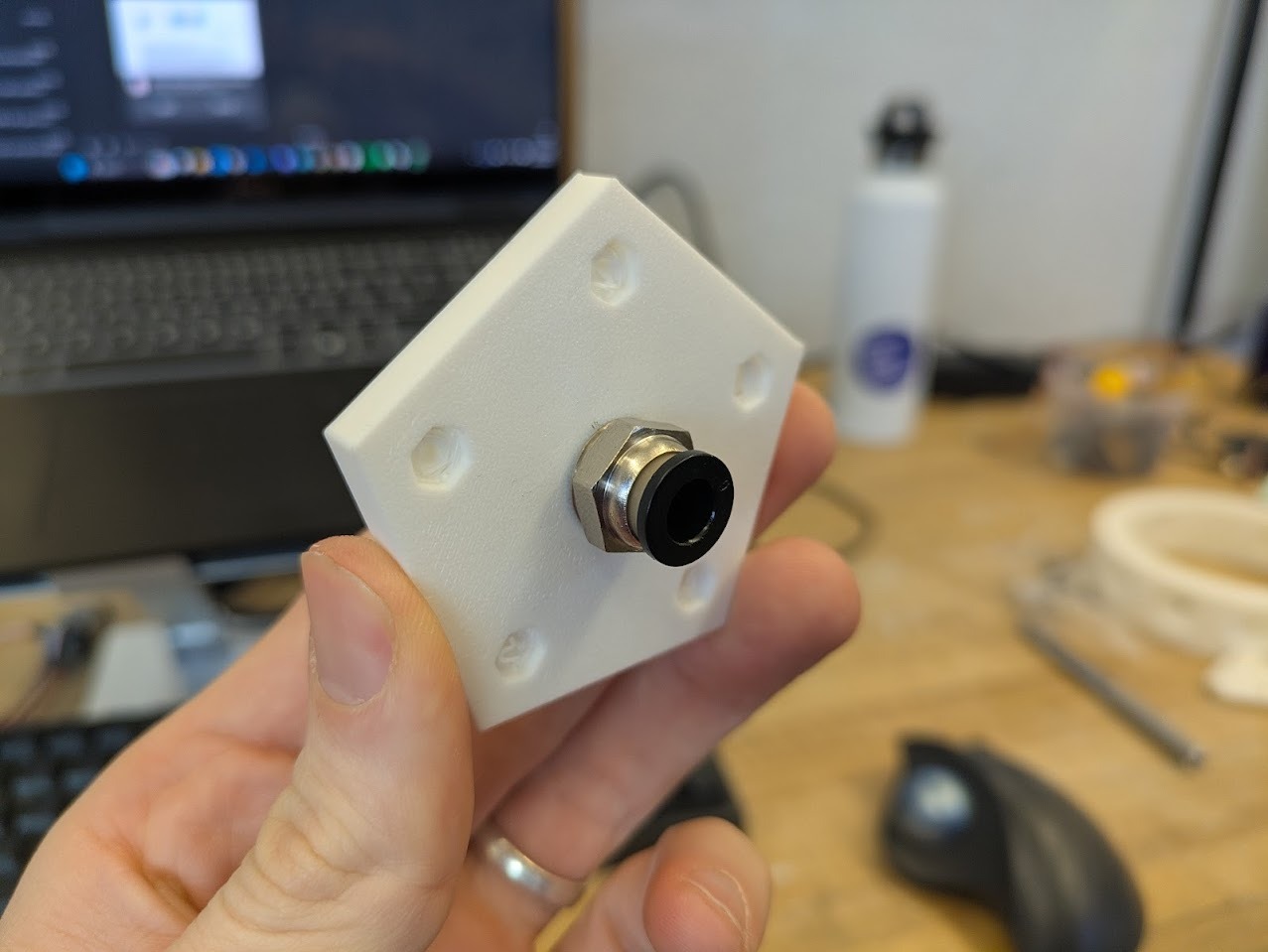
PTFE tube mount fit test
The corner nodes of the geometry serve as both structural and luminous anchors. Each node sits between three piston arms that rotate away from it, making it a natural site for light emission. The intended configuration places twenty NeoPixels in sequence across these nodes.
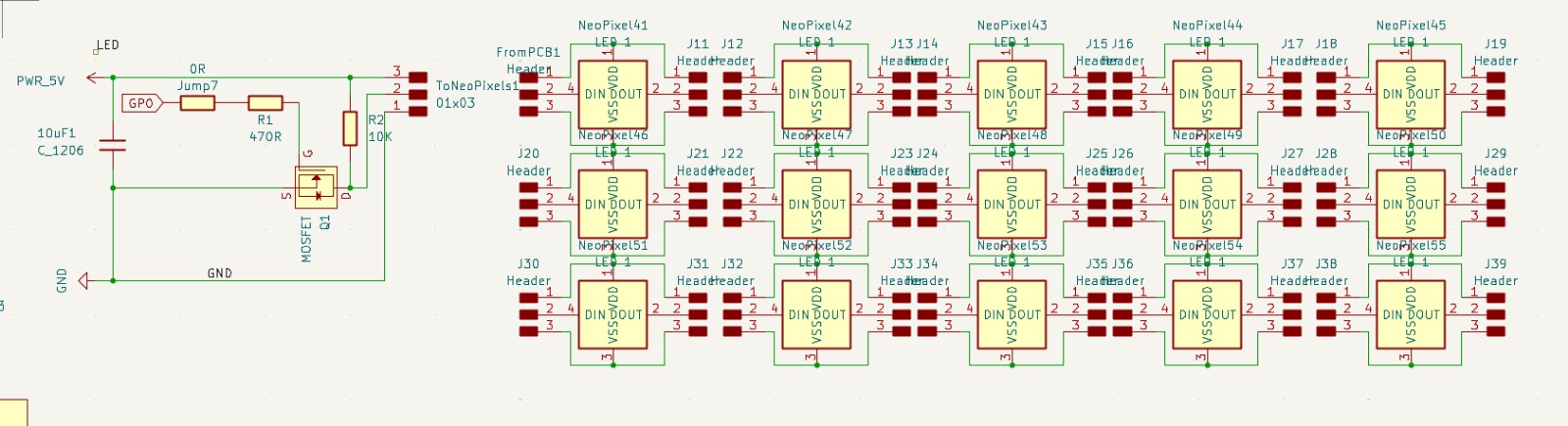
Schematic for neopixel LEDs
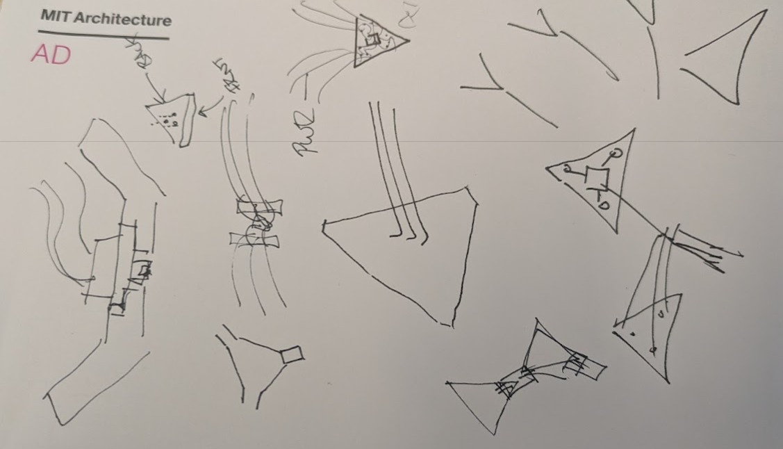
sketches for corner node lighting1
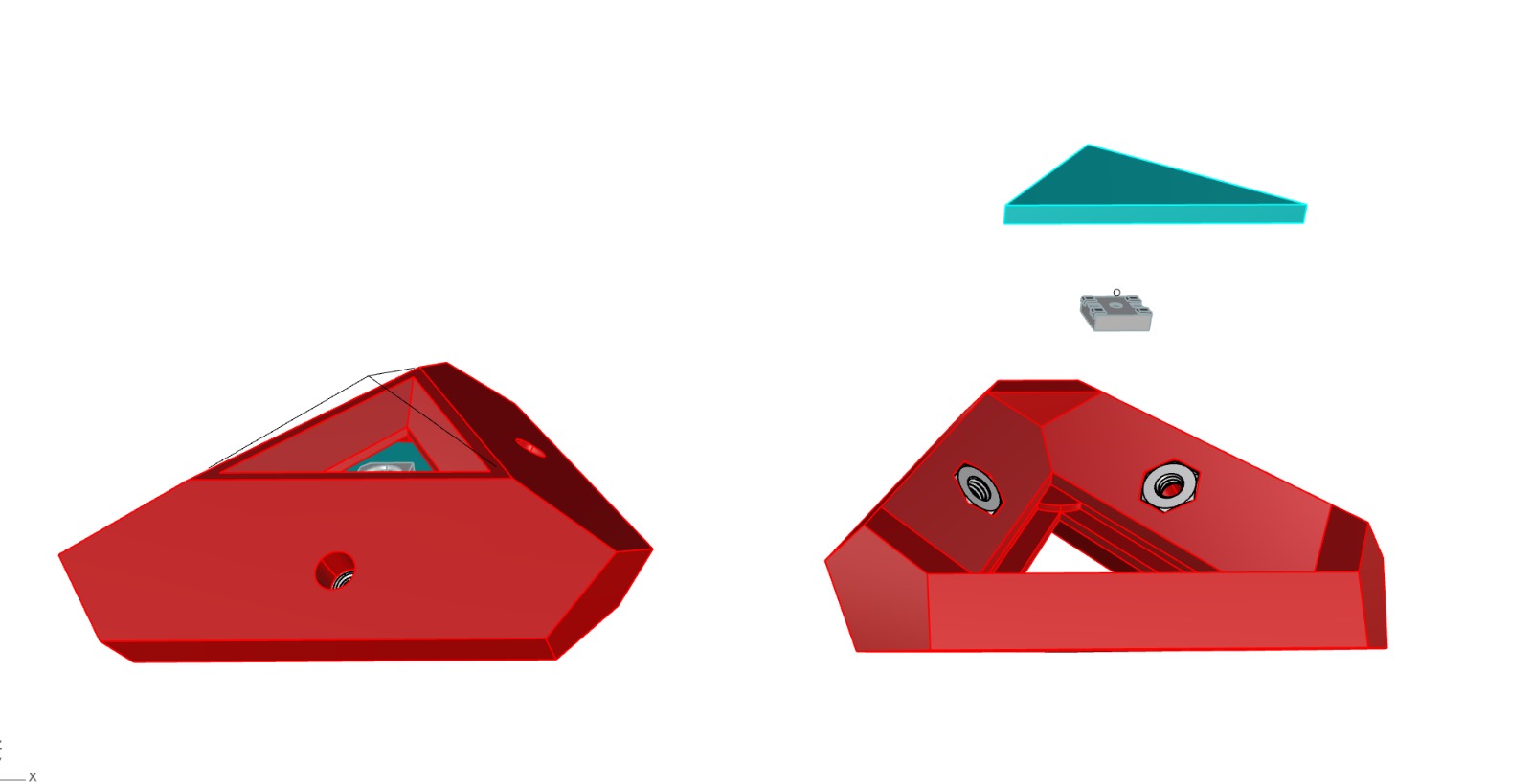
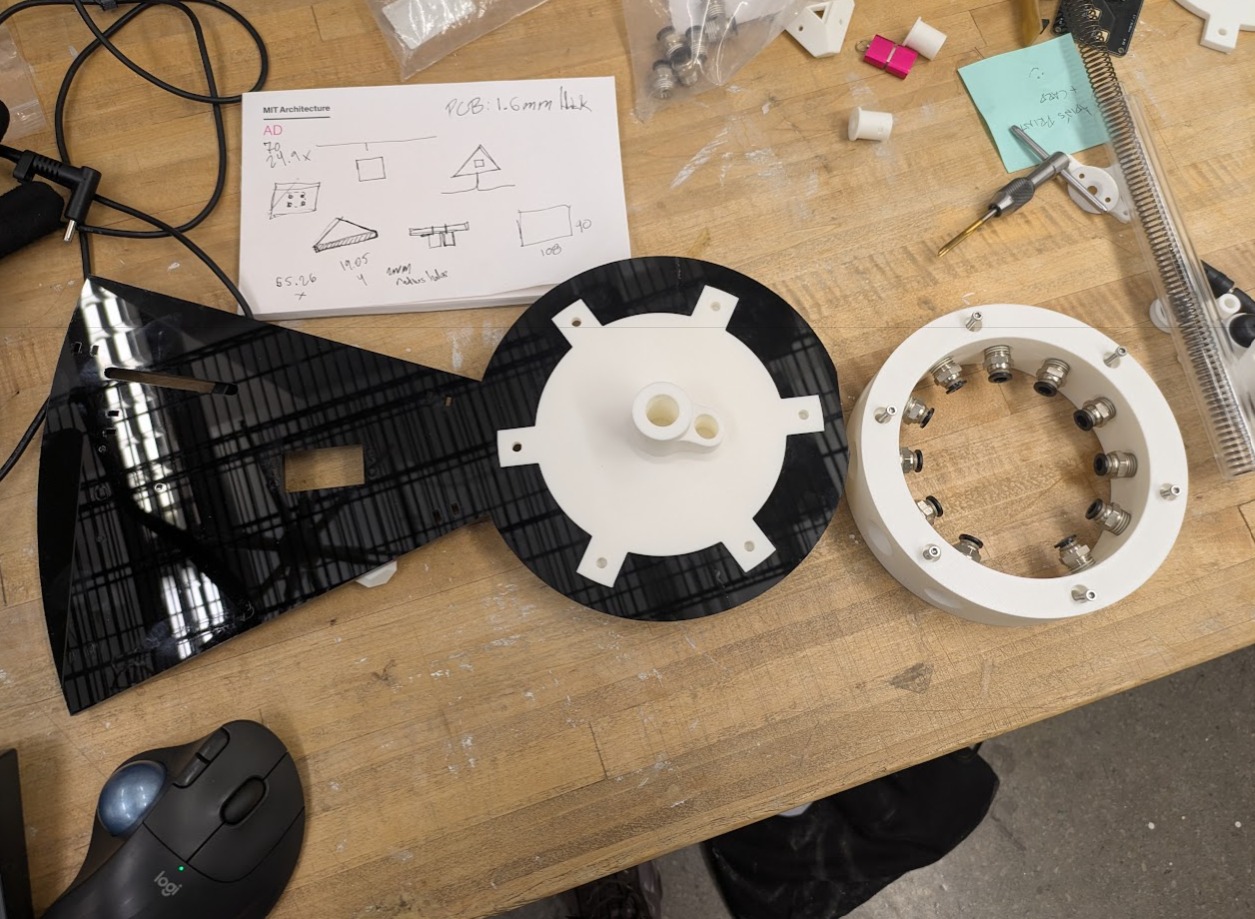
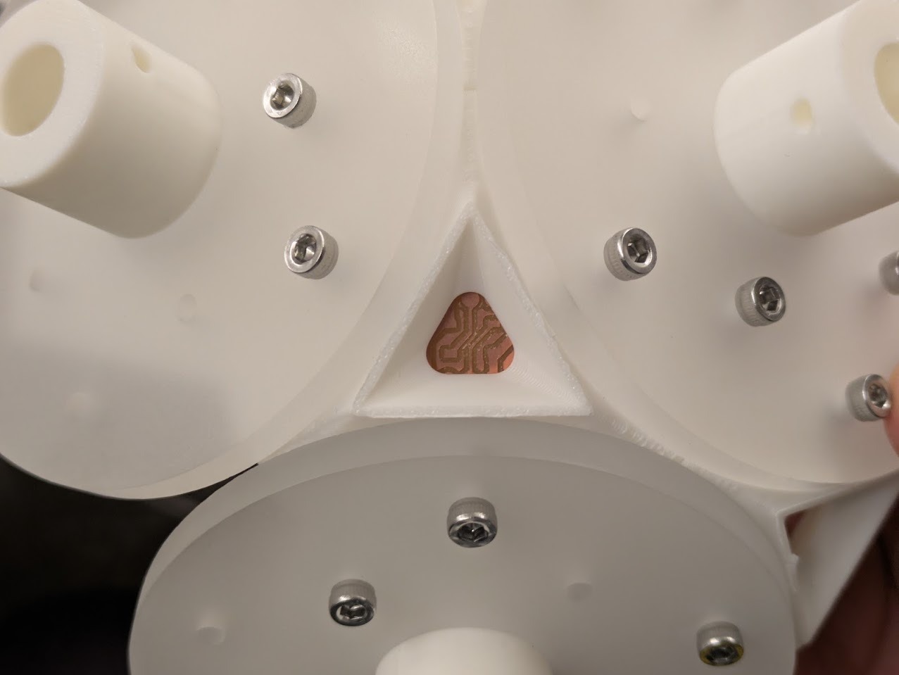
Corner node 3D model. Red denotes 3D print, cyan is PCB board.
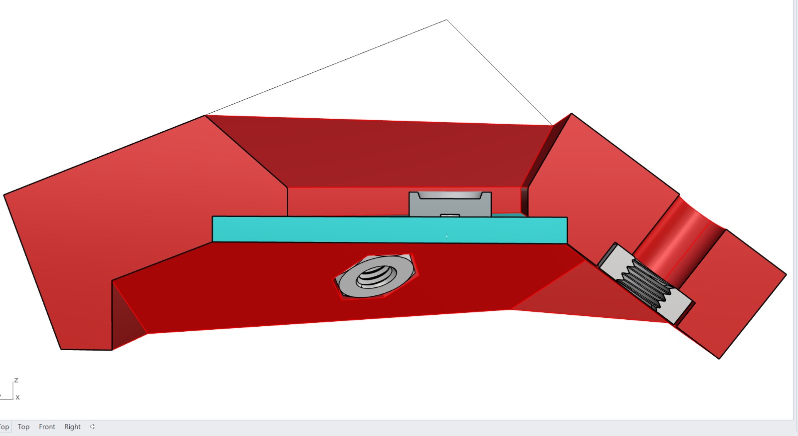
Cross section showing how the PCB w neopixel is installed.
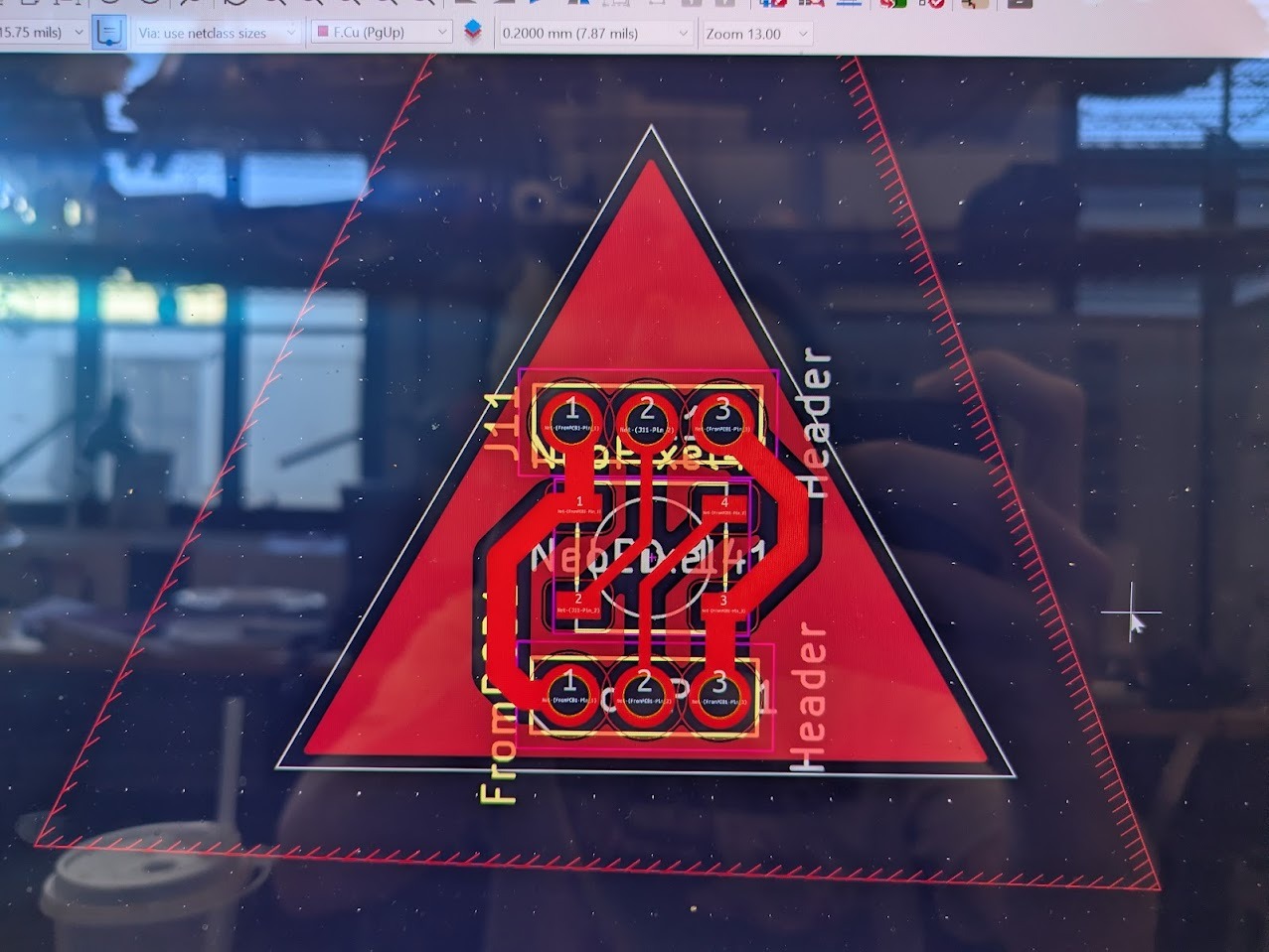
PCB design with through holes. The idea is that the headers are attached to the back and allow internal wiring between the 20x nodes.
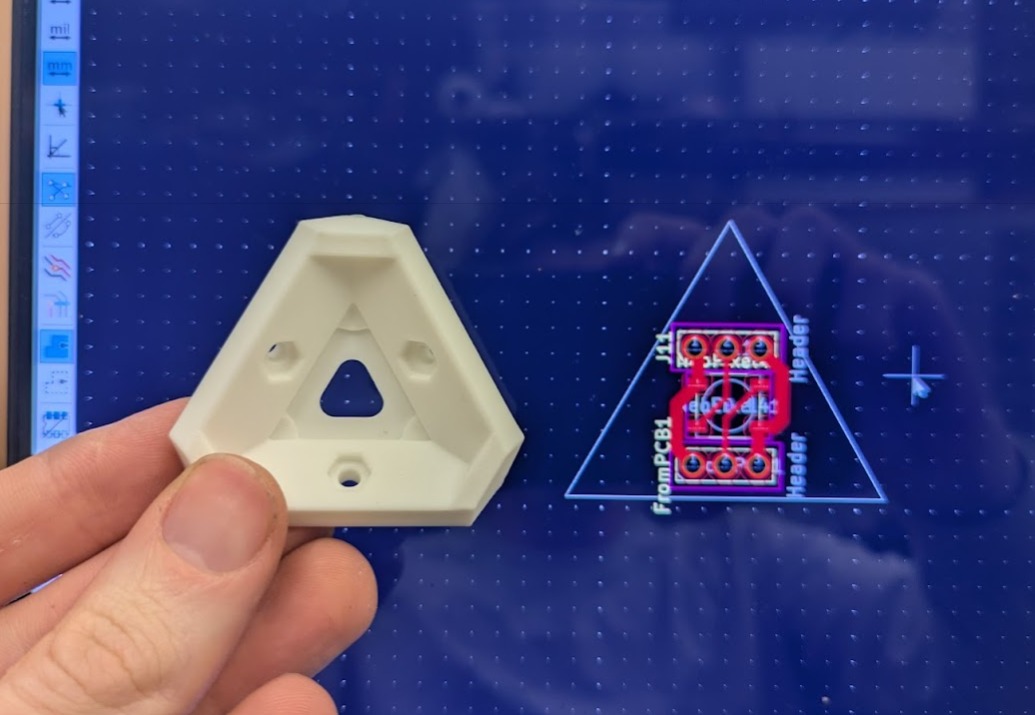
PCB layout and final 3D Print for reference.
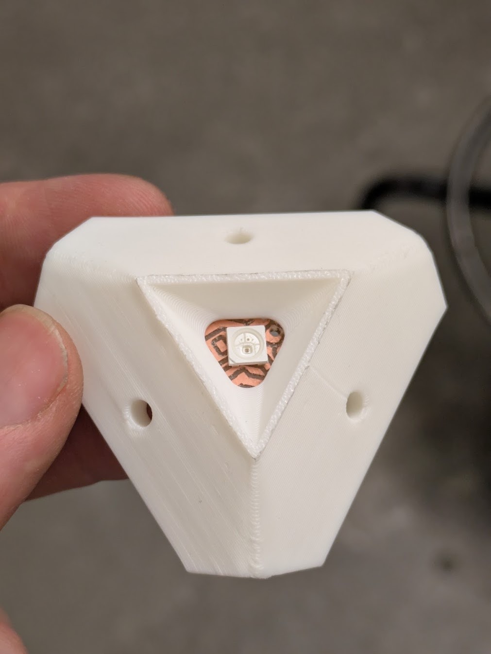
Example from final assembly!
PCB Design
The custom PCB integrates the Pico W, PCA9685 servo driver, power distribution, and sensor headers. High-current servo power is isolated from logic power while maintaining a shared ground reference.
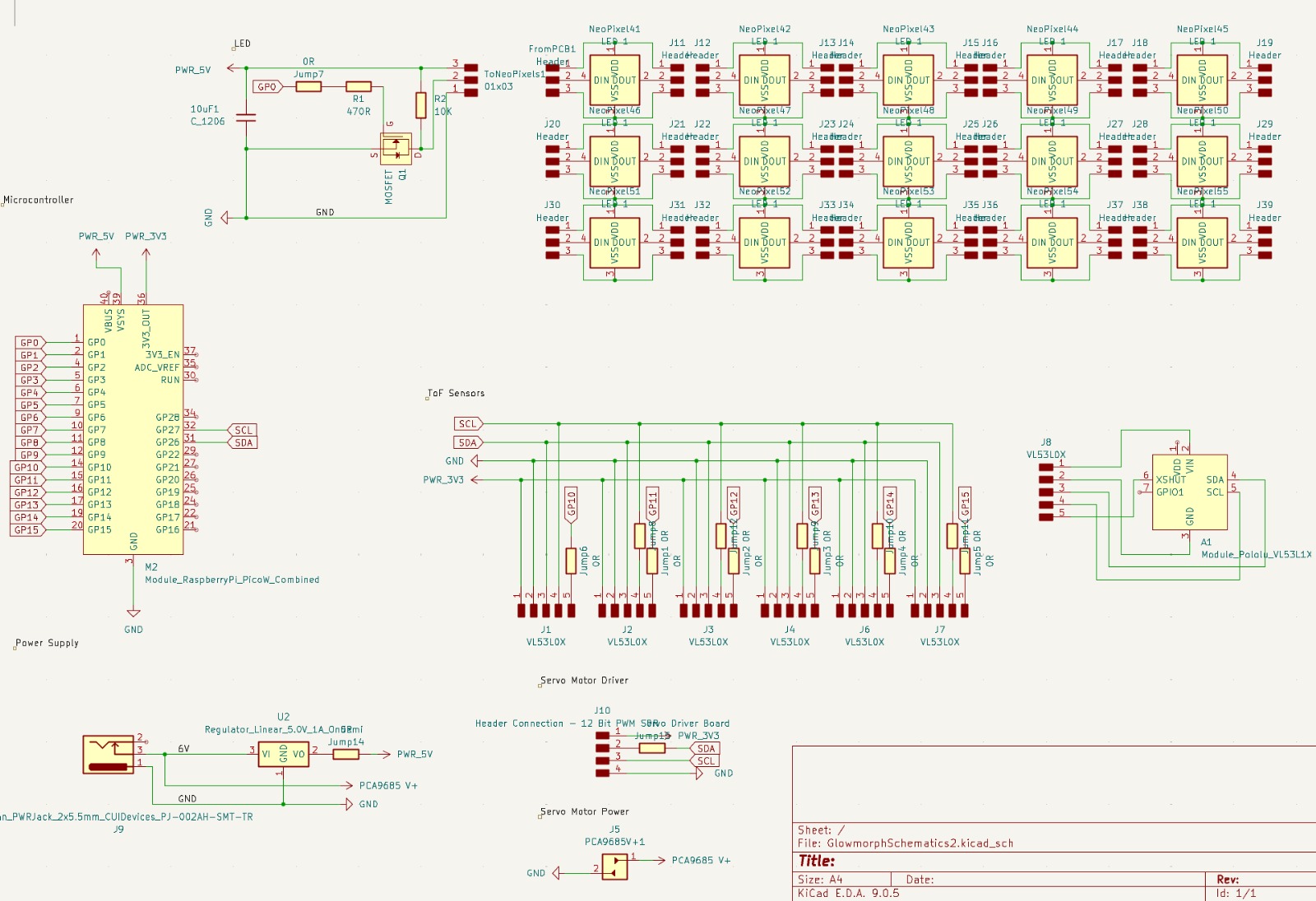
Final Schematic
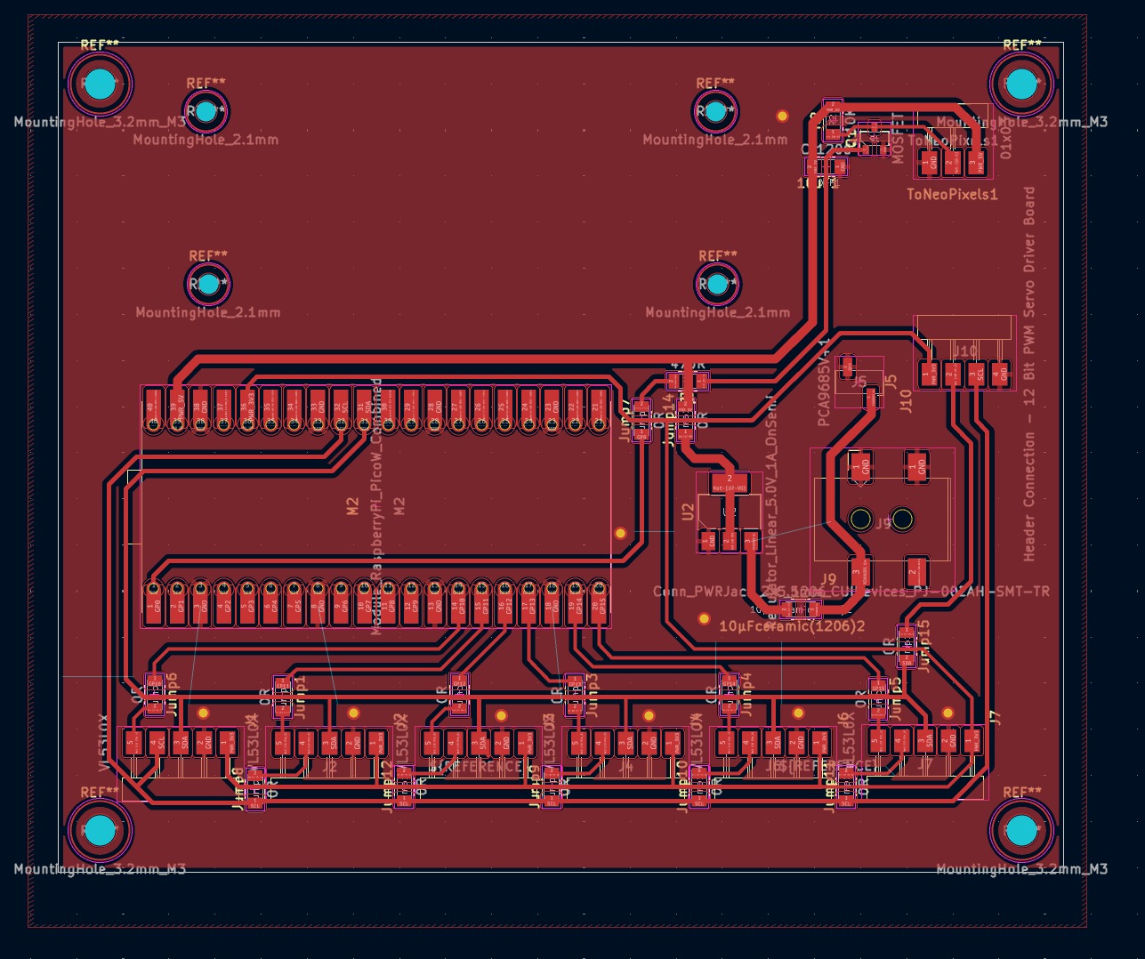
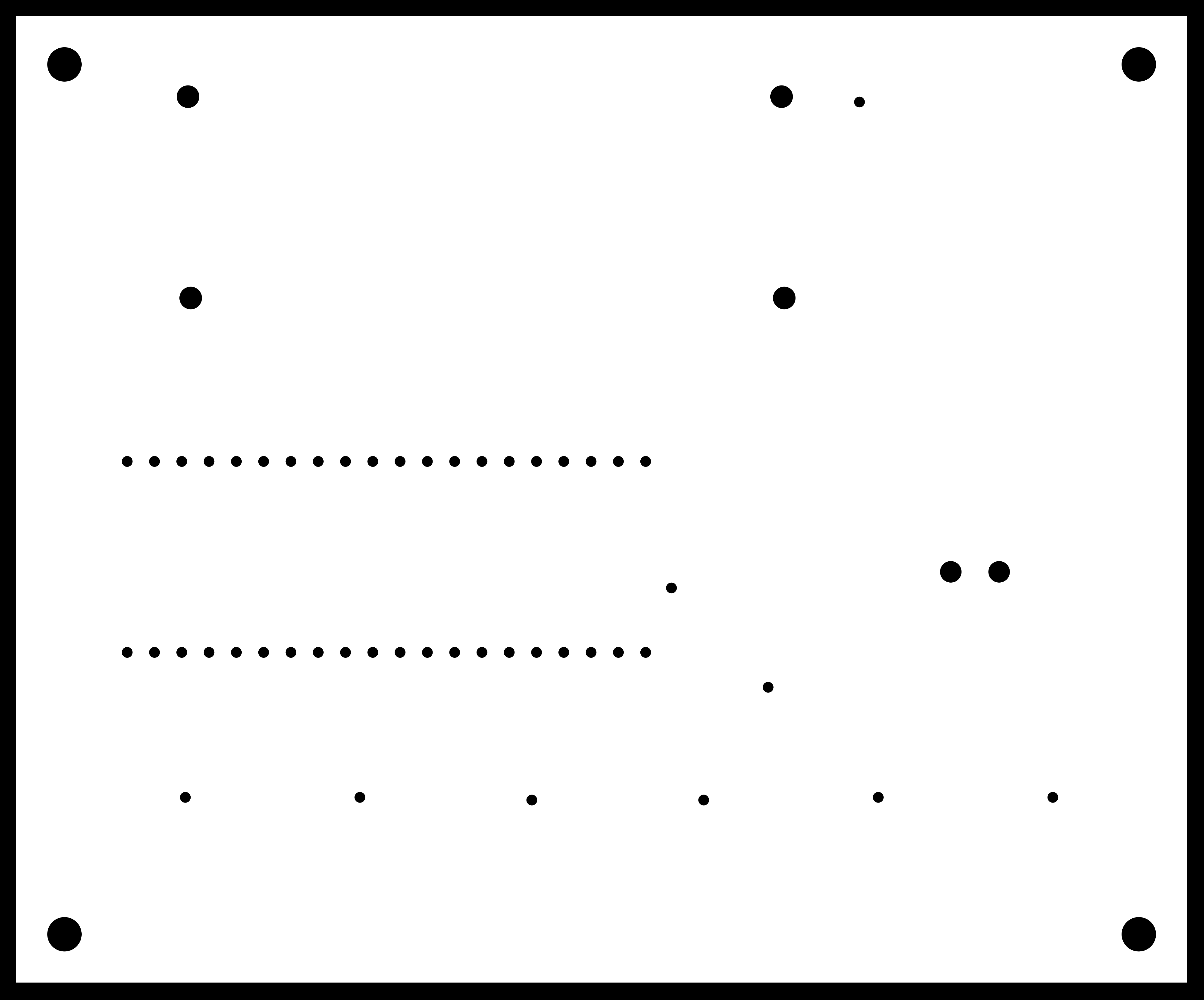
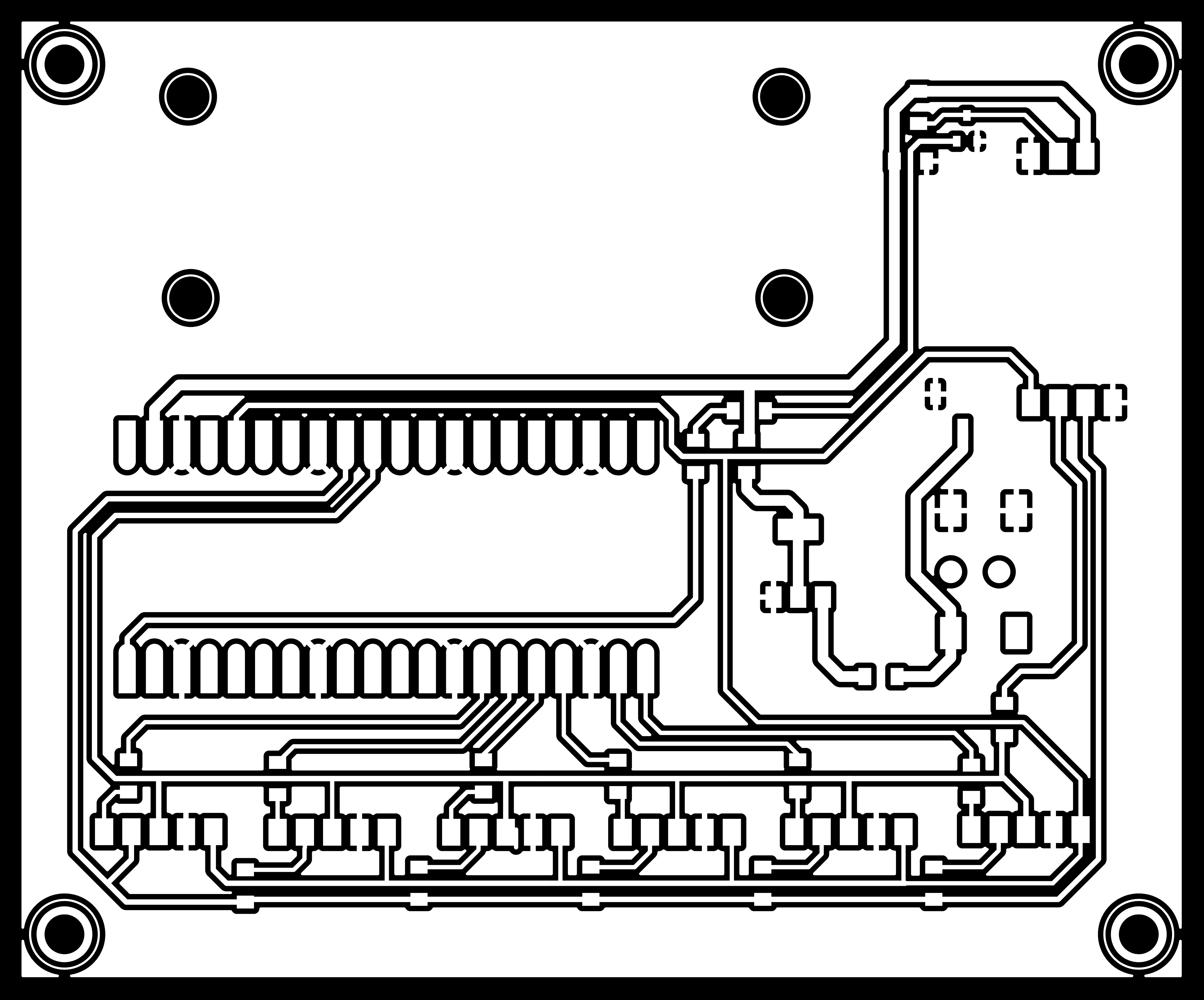
Final PCB Layout
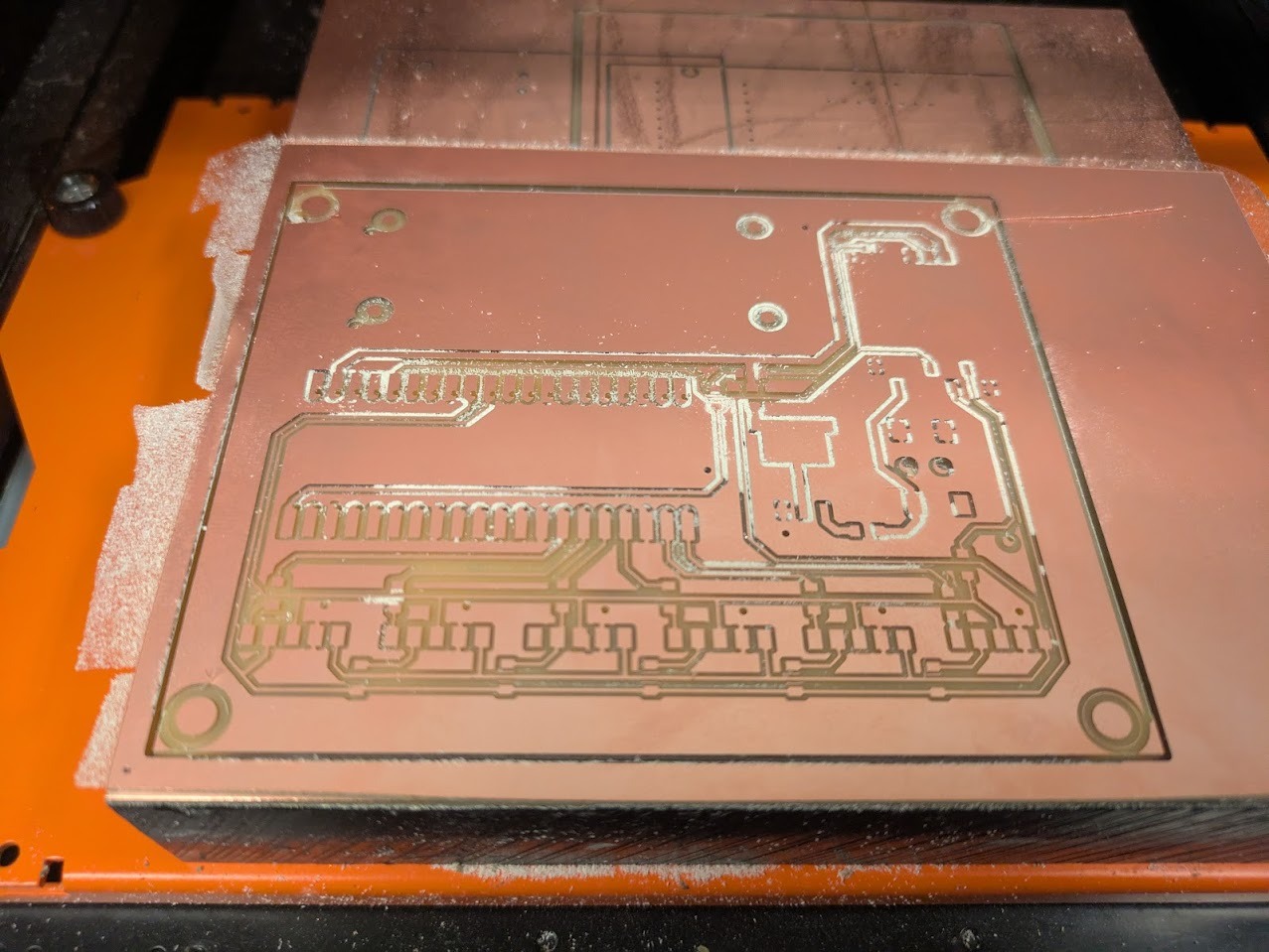
Initial milling attempts produced poor trace quality due to warped copper stock. Switching to double-sided copper boards—recommended by Jen—resolved the issue immediately.
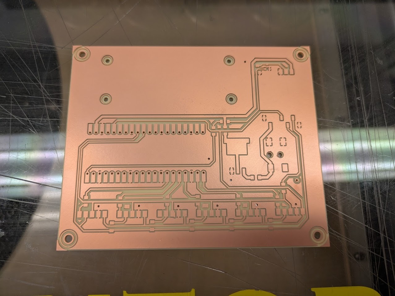
Much better! the issue was with the warped plane. Switching to a double sided helped.
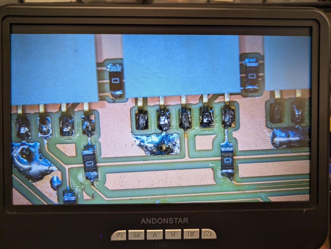
Isolated ground islands were stitched together using metal pins soldered on both sides of the board. While visually crude, this solution proved reliable.
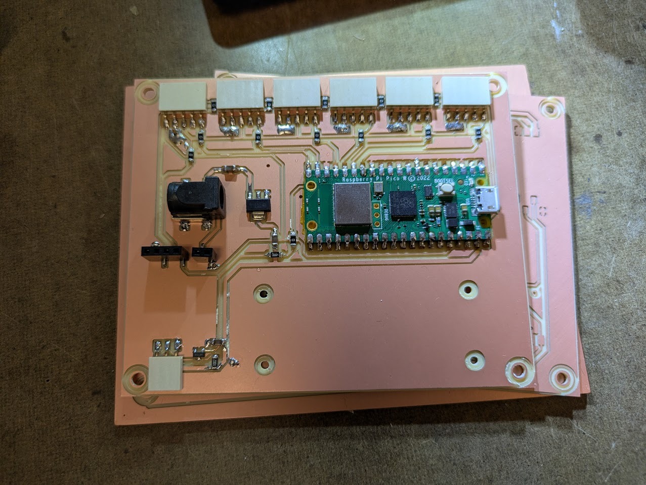
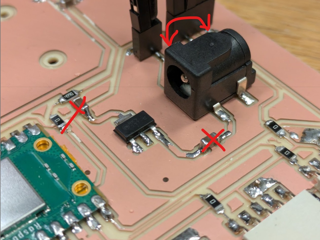
My board was having issues with delivering the 6V to the motor board. When reviewing it with Anthony he pointed out that I had capacitors installed completely wrong. On top of that, the power jack was flipped. Weirdly enough, the capacitors helped me not blow my picoW! happy accident.
Above is the mistaken board.
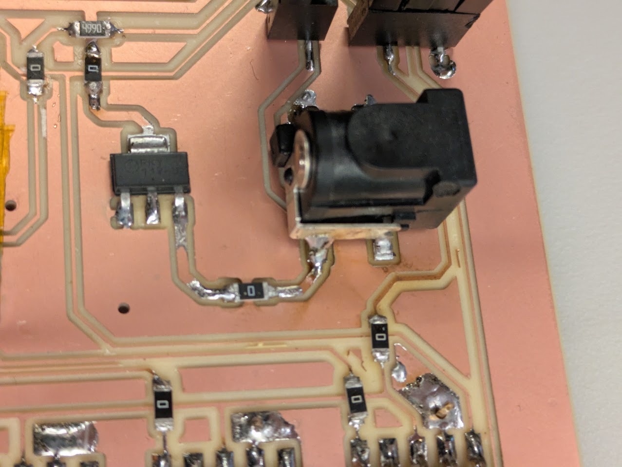
Above is the fix, with 0 Ohm resistors replacing the erroneous capacitors.
Final PCB board
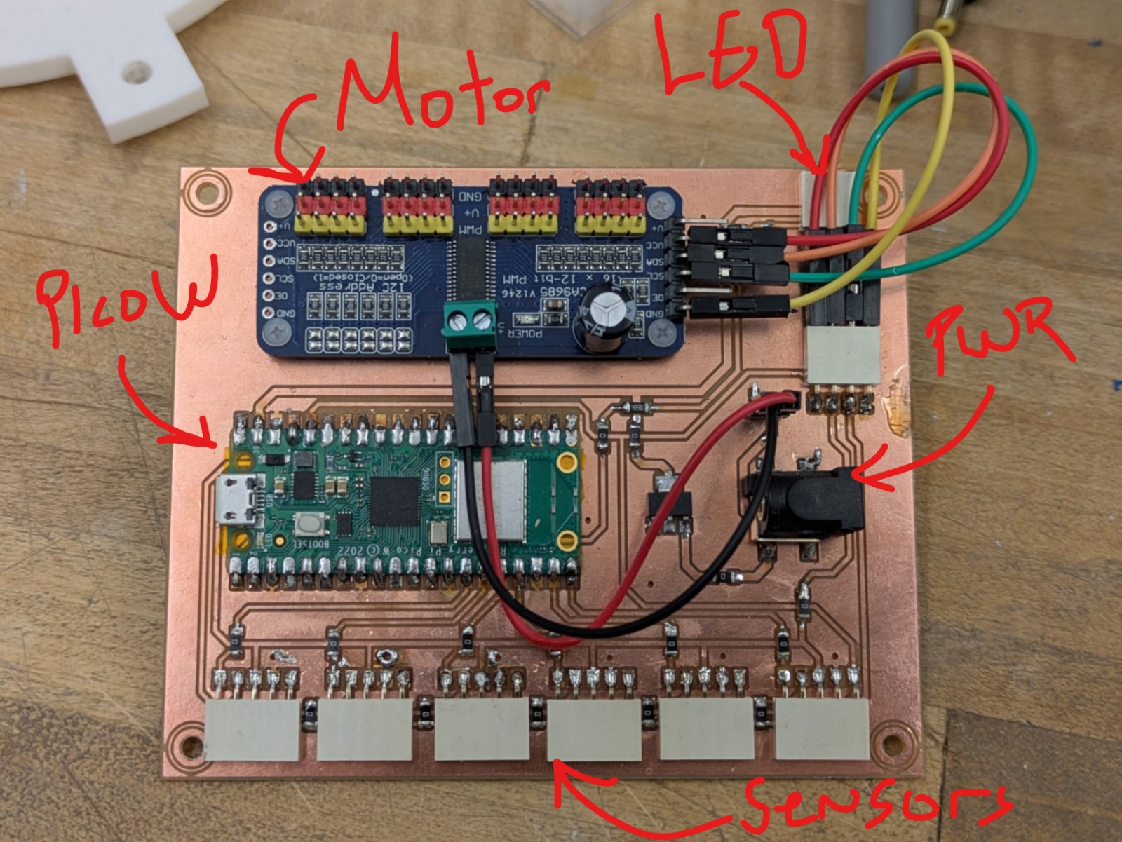
Final PCB board annotated.
Base Designing and Building
Before assembling the parts, I wanted to frost the acrylic. I like the look of frosted acrylic. Aesthetically it can both hide and reveal the contents of a machine, raising the mystery as well as showing what’s hjappening inside. In addition, its creates a forgiving surface that does not show scratches. I learned how to use the sandblaster in the architecture shops.
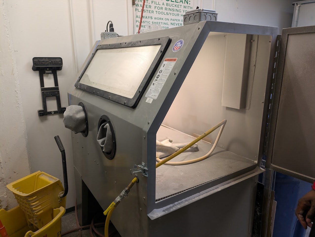
The sandblaster includes both lighting as well as a vacuum. It is critical to use a respirator when operating. I was instructed to go in short spurts and not a prolonged spray as the friction creates tremendous kinetic electricity buildup. In addition, after spraying, you should always give 5 minutes for the sand to settle. It is extremely hazardous if breathed in but is safe if handled properly.
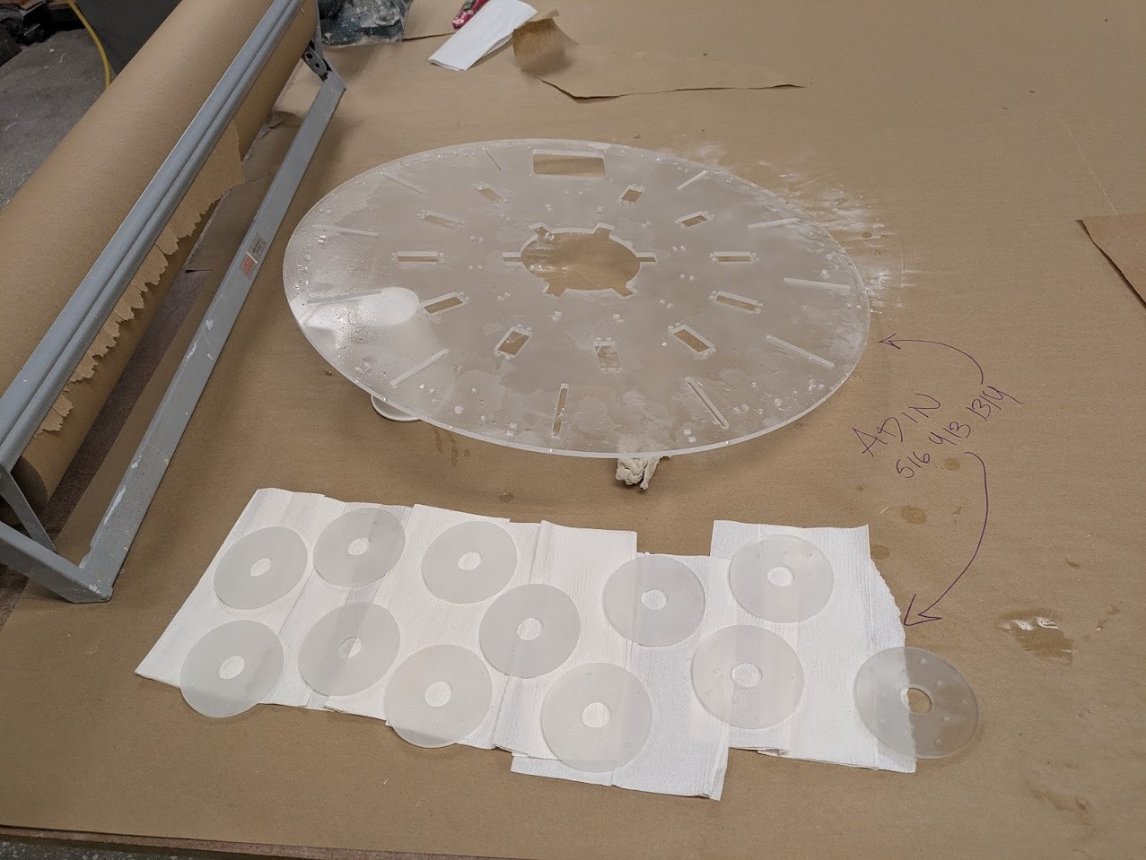
Final parts after sandblasting
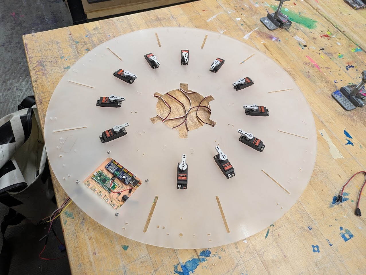
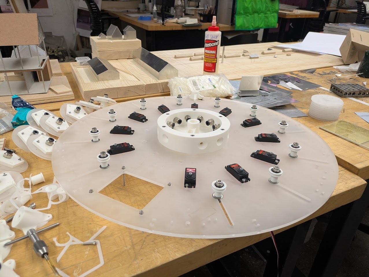
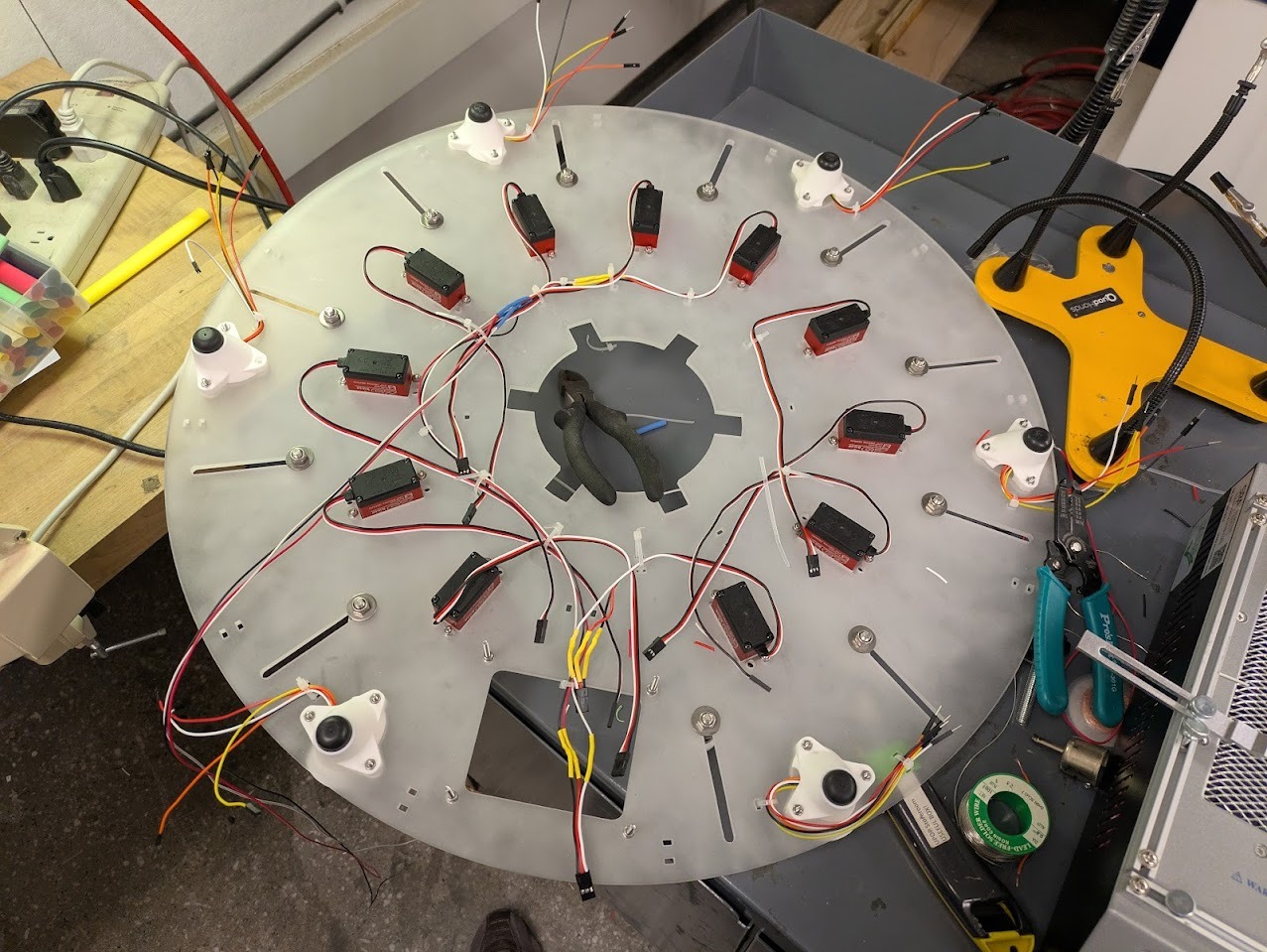
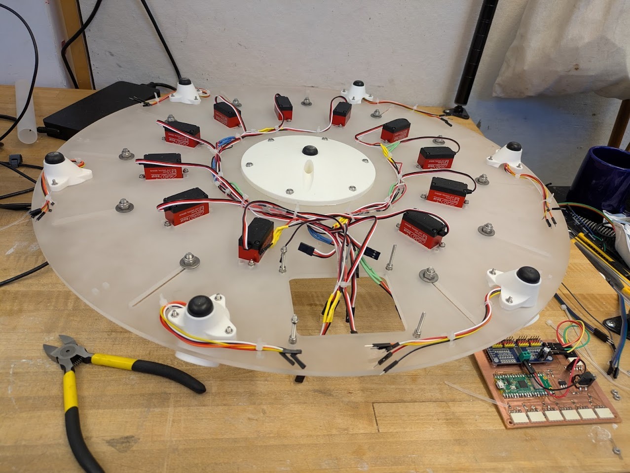
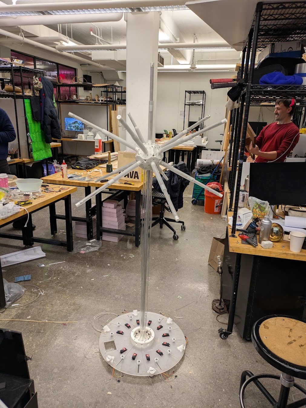
The base consists of eleven servo motors arranged in a polar array. Each servo drives a cable pulley rotating between 0–270 degrees. The cable passes through a tensionable jockey wheel mounted in a slot, then onto a partially threaded bolt with a free-spinning ball bearing.
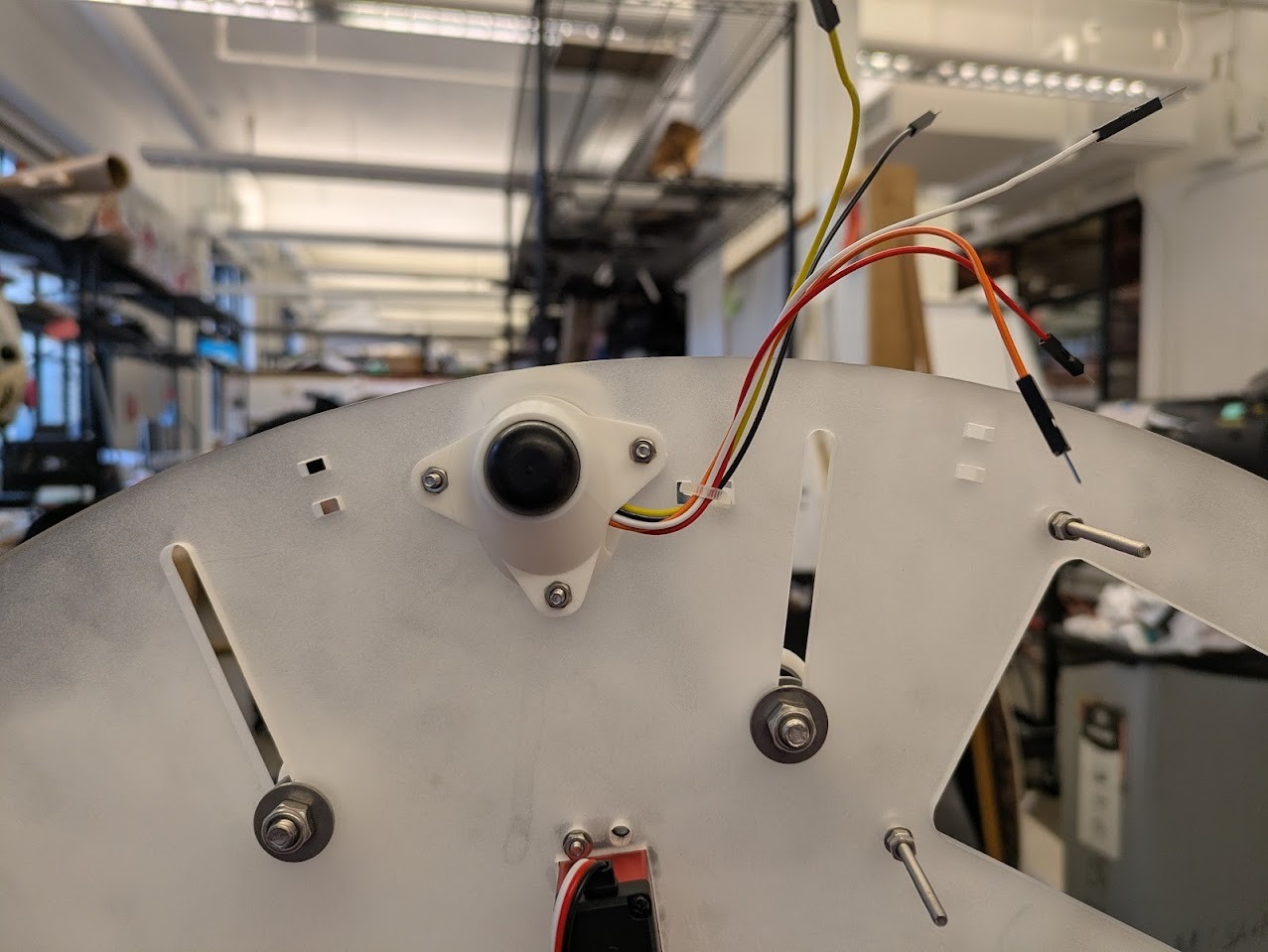
Cables converge at a central gathering point using push-to-connect pneumatic fittings, which interface with PTFE tubing leading upward to the suspended light module. Six Time-of-Flight sensors are embedded in the base to detect proximity.
I had to do a lot of test fitting. A lot. I think between the laser cutting and 3d printed parts, there were issues of kerf from the cutting and offsetting from the printing. For reference, I ended up not worrying about laser cut kerf and chose to rely on the 3D print being slightly offset from the design. When interfacing with other 3D printed parts or hardware, I used a .1mm offset.
Final PCB in location
Above shows the mounting process of how to get the servos into place. It involves opening up the gearbox.
The initial design did not give nearly enough space for the cables to fit. Initially I tried to just use solid core wires, but decided it was worth tweaking and reprinting to give myself more room.
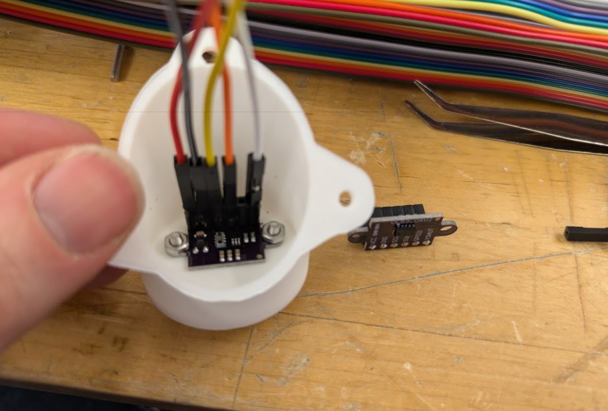
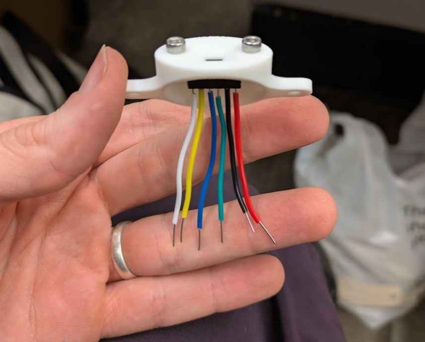
Sensor mounting. It is critical to track the colors as when they are closed up, it's difficult to follow where wires should go.
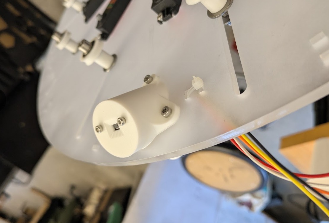
Top mounting
Bottom mounting with integrated feet.
Wires before routing and extending motor cables.
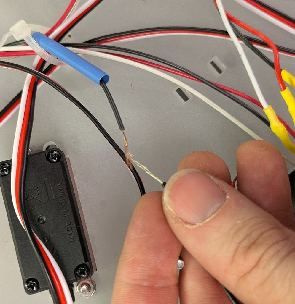
Splicing technique for extending wires. weave the wires together then heat shrink them together.
Testing the bottom support, the 3D print was a critical failure point. This would have to get redesigned.
I left mounting holes in the plexiglass for small zip ties.

Final base built!
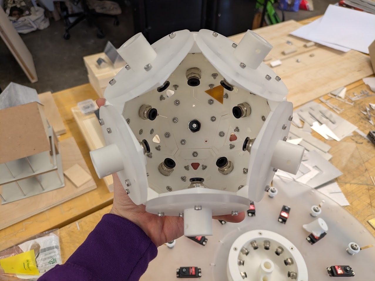
Kinetic Pendant Build
I moved into construction of the pendant with a ton of assumptions. One of which was that I'd be able to mount the acrylic rods that were atually pretty delicate. And inside of them are nylon self-lubricating washers which would be enough for sliding. Shortly after trying to assemble, I realized that the nylon washers' OD was too large and so they didn't fit into the outer tubes.
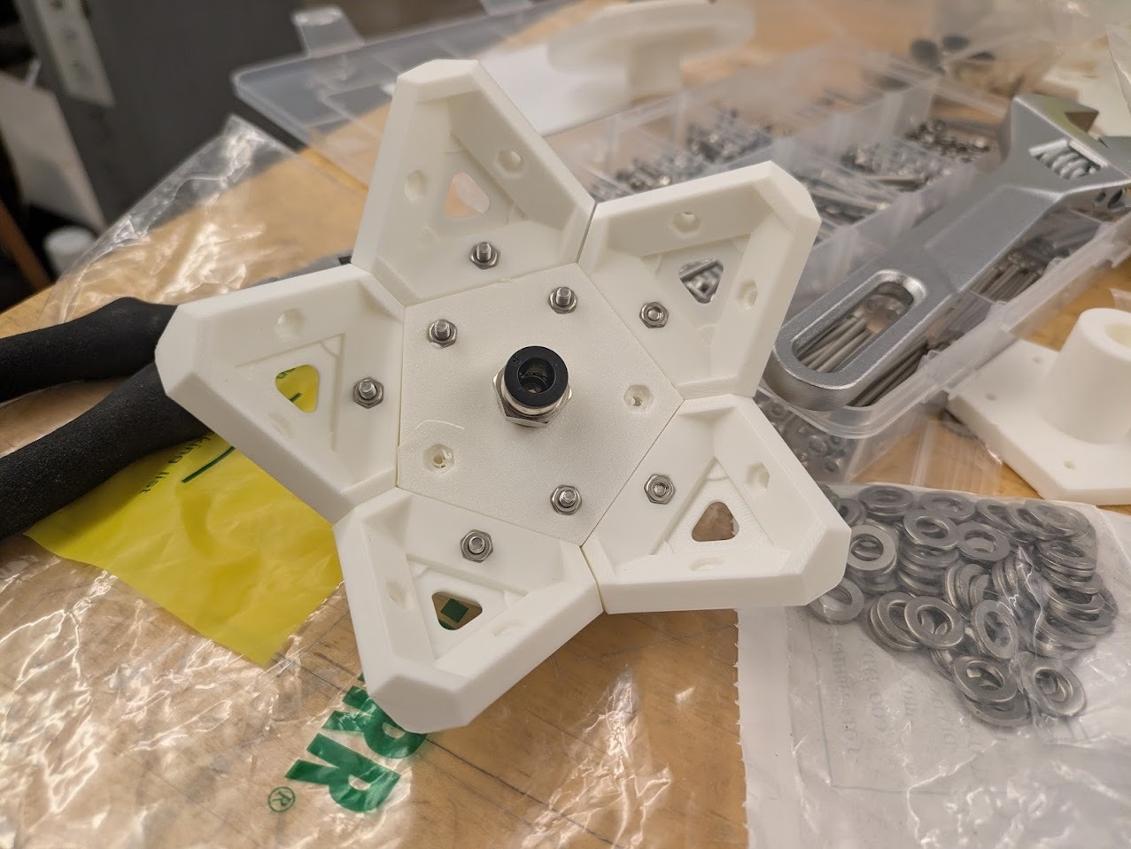
Initial tiling assembled.
Tesselation continues.
Mounting test for corner node neopixel PCB.
Mounting test for corner node neopixel PCB.
Assembly continues.
First fitting test of piston arms onto base light fixture geometry.
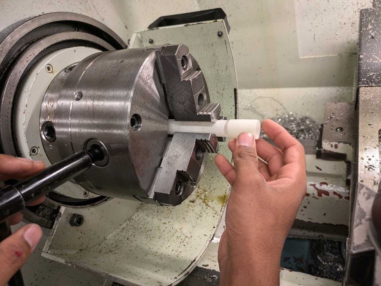
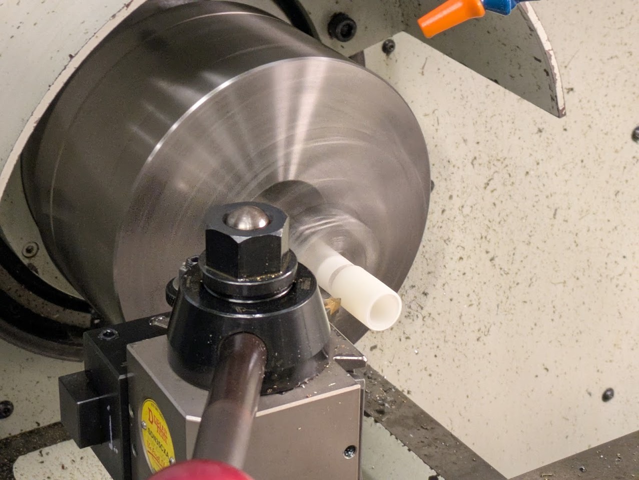
To fix the issue of the mis-fit nylon washers, my friend Varun helped me with the lathe in the Deep fabrication lab. It turned out relatively easy, we zero'd the tool out and removed small layers until there was no more friction. THANKS VARUN!
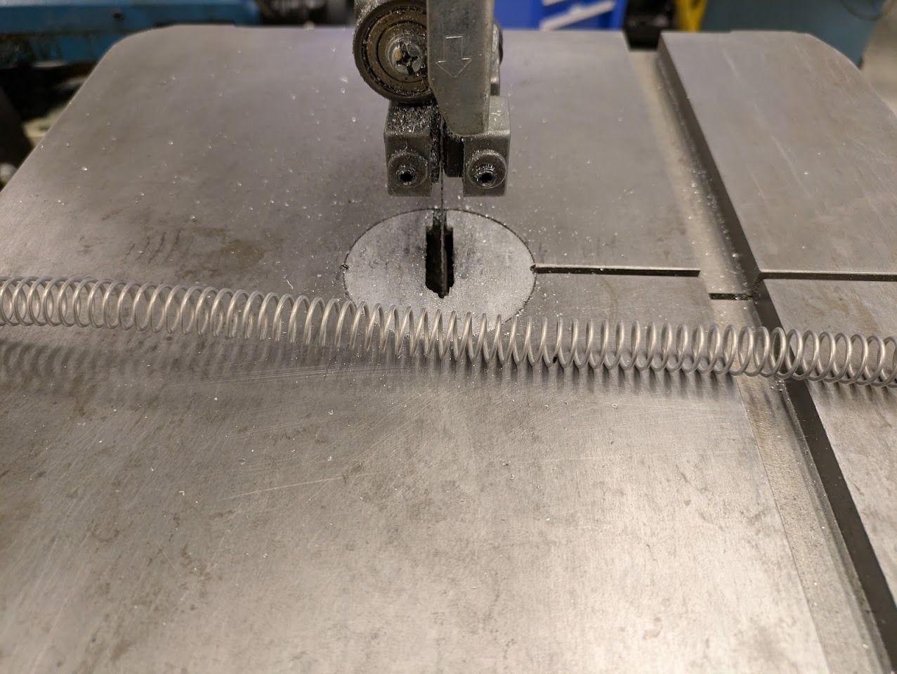
To cut the steel springs to size, I used the metal bandsaw. The trick is to pull it through and have the band saw blade cut the inner face outwards.
Assembly was... interesting. It turned out to be very tricky to get all the PTFE tubes to mount inside of the polyhedral light fixture. In retrospect I should have assembled the light with the tubing already in place. My two friends helped me with getting them all into place. Shout out to Victor and Varun!
Loading the PTFE tubing into the build.
Tubing in place, and outer piston arms are attached via bolts. The process was to slide cable through the light into the ptfe tube, pass it through the base into the piston cable pulley arm. Then sinch off the cable loop into the piston arm end through a spring cut to size.
Final assembled! now onto motors.
Motor & Sensor Testing
First I needed to test my PCB with 3 motors. I wanted to check to make sure that the 6V was working and that my board would move the motors outside of a USB powered 5V connection. I referenced Adafruit's library, available here: https://learn.adafruit.com/16-channel-pwm-servo-driver/using-the-adafruit-library
    /***************************************************
  This is an example for our Adafruit 16-channel PWM & Servo driver
  Servo test - this will drive 8 servos, one after the other on the
  first 8 pins of the PCA9685


  Pick one up today in the adafruit shop!
  ------> http://www.adafruit.com/products/815

  These drivers use I2C to communicate, 2 pins are required to
  interface.


  Adafruit invests time and resources providing this open source code,
  please support Adafruit and open-source hardware by purchasing
  products from Adafruit!


  Written by Limor Fried/Ladyada for Adafruit Industries.
  BSD license, all text above must be included in any redistribution
 ****************************************************/


#include
#include


// called this way, it uses the default address 0x40
Adafruit_PWMServoDriver pwm = Adafruit_PWMServoDriver();
// you can also call it with a different address you want
//Adafruit_PWMServoDriver pwm = Adafruit_PWMServoDriver(0x41);
// you can also call it with a different address and I2C interface
//Adafruit_PWMServoDriver pwm = Adafruit_PWMServoDriver(0x40, Wire);


// Depending on your servo make, the pulse width min and max may vary, you
// want these to be as small/large as possible without hitting the hard stop
// for max range. You'll have to tweak them as necessary to match the servos you
// have!
#define SERVOMIN  150 // This is the 'minimum' pulse length count (out of 4096)
#define SERVOMAX  600 // This is the 'maximum' pulse length count (out of 4096)
#define USMIN  600 // This is the rounded 'minimum' microsecond length based on the minimum pulse of 150
#define USMAX  2400 // This is the rounded 'maximum' microsecond length based on the maximum pulse of 600
#define SERVO_FREQ 50 // Analog servos run at ~50 Hz updates


// our servo # counter
uint8_t servonum = 0;


void setup() {
  Serial.begin(9600);
  Serial.println("8 channel Servo test!");


  pwm.begin();
  /*
   * In theory the internal oscillator (clock) is 25MHz but it really isn't
   * that precise. You can 'calibrate' this by tweaking this number until
   * you get the PWM update frequency you're expecting!
   * The int.osc. for the PCA9685 chip is a range between about 23-27MHz and
   * is used for calculating things like writeMicroseconds()
   * Analog servos run at ~50 Hz updates, It is importaint to use an
   * oscilloscope in setting the int.osc frequency for the I2C PCA9685 chip.
   * 1) Attach the oscilloscope to one of the PWM signal pins and ground on
   *    the I2C PCA9685 chip you are setting the value for.
   * 2) Adjust setOscillatorFrequency() until the PWM update frequency is the
   *    expected value (50Hz for most ESCs)
   * Setting the value here is specific to each individual I2C PCA9685 chip and
   * affects the calculations for the PWM update frequency.
   * Failure to correctly set the int.osc value will cause unexpected PWM results
   */
  pwm.setOscillatorFrequency(27000000);
  pwm.setPWMFreq(SERVO_FREQ);  // Analog servos run at ~50 Hz updates


  delay(10);
}


// You can use this function if you'd like to set the pulse length in seconds
// e.g. setServoPulse(0, 0.001) is a ~1 millisecond pulse width. It's not precise!
void setServoPulse(uint8_t n, double pulse) {
  double pulselength;

  pulselength = 1000000;   // 1,000,000 us per second
  pulselength /= SERVO_FREQ;   // Analog servos run at ~60 Hz updates
  Serial.print(pulselength); Serial.println(" us per period");
  pulselength /= 4096;  // 12 bits of resolution
  Serial.print(pulselength); Serial.println(" us per bit");
  pulse *= 1000000;  // convert input seconds to us
  pulse /= pulselength;
  Serial.println(pulse);
  pwm.setPWM(n, 0, pulse);
}


void loop() {
  // Drive each servo one at a time using setPWM()
  Serial.println(servonum);
  for (uint16_t pulselen = SERVOMIN; pulselen < SERVOMAX; pulselen++) {
    pwm.setPWM(servonum, 0, pulselen);
  }


  delay(500);
  for (uint16_t pulselen = SERVOMAX; pulselen > SERVOMIN; pulselen--) {
    pwm.setPWM(servonum, 0, pulselen);
  }


  delay(500);


  // Drive each servo one at a time using writeMicroseconds(), it's not precise due to calculation rounding!
  // The writeMicroseconds() function is used to mimic the Arduino Servo library writeMicroseconds() behavior.
  for (uint16_t microsec = USMIN; microsec < USMAX; microsec++) {
    pwm.writeMicroseconds(servonum, microsec);
  }


  delay(500);
  for (uint16_t microsec = USMAX; microsec > USMIN; microsec--) {
    pwm.writeMicroseconds(servonum, microsec);
  }


  delay(500);


  servonum++;
  if (servonum > 7) servonum = 0; // Testing the first 8 servo channels
}
Happy with the results I thought I would go ahead and add the other 11. This is where I started to get some problems.
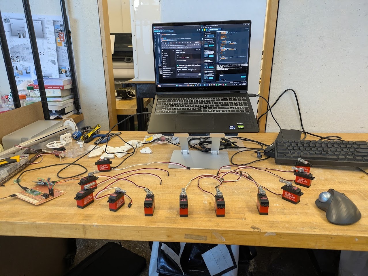
11 x 25kg motor array.
Early debugging centered around I2C communication on the Pico W. The critical realization was that my board used the PicoW second I2C bus, Wire1, mapped to GPIO 26 (SDA) and 27 (SCL). Once configured consistently, communication stabilized.
Power issues were ultimately current-related rather than voltage-related. The 6V supply held voltage but could not deliver sufficient amperage during servo load spikes. Increasing available current resolved the brownouts. I reached out to our TA, Anthony, to help me diagnose the issue. He offered the same voltage power brick but with a higher Amperage. That seemed to really help.
    /***************************************************
  This is an example for our Adafruit 16-channel PWM & Servo driver
  Servo test - this will drive 8 servos, one after the other on the
  first 8 pins of the PCA9685


  Pick one up today in the adafruit shop!
  ------> http://www.adafruit.com/products/815

  These drivers use I2C to communicate, 2 pins are required to
  interface.


  Adafruit invests time and resources providing this open source code,
  please support Adafruit and open-source hardware by purchasing
  products from Adafruit!


  Written by Limor Fried/Ladyada for Adafruit Industries.
  BSD license, all text above must be included in any redistribution
 ****************************************************/


#include
#include

#include
#include
#include


Adafruit_PWMServoDriver pwm = Adafruit_PWMServoDriver(0x40, Wire1);


#define SERVO_MIN 150
#define SERVO_MAX 600


int angleToPulse(float angleDeg) {
  angleDeg = constrain(angleDeg, 0, 270);
  float pulse = SERVO_MIN + (angleDeg / 270.0f) * (SERVO_MAX - SERVO_MIN);
  return (int)pulse;
}


void setup() {
  Wire1.setSDA(26);   // SDA to pin 31
  Wire1.setSCL(27);   // SCL to pin 32
  Wire1.begin();


  pwm.begin();
  pwm.setPWMFreq(50);
  delay(10);
}


void sweepServo(int ch) {
  for (int a = 0; a <= 270; a += 4) {
    pwm.setPWM(ch, 0, angleToPulse(a));
    delay(5);
  }
  delay(100);
  for (int a = 270; a >= 0; a -= 4) {
    pwm.setPWM(ch, 0, angleToPulse(a));
    delay(5);
  }
  delay(100);
}


void loop() {
  for (int ch = 0; ch < 11; ch++) {  // channels 0 through 10
    sweepServo(ch);
  }
}
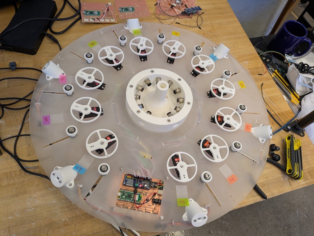
Motor Roll-call
After the build I went to start testing out some test scripts. Two motors failed late in the process, likely due to earlier brownouts or mechanical bottoming-out. With limited time remaining, I accepted partial functionality. I did not come up w a system to translate the addresses of the motors to the locations of the pistons. I therefore wanted to do a “roll call” to label each motor locatoin so taht I can be specific in my motor controls. I wrote a small script that would wiggle each motor in sequence so that I can map by hand, the location of motors.
#include
#include


Adafruit_PWMServoDriver pwm = Adafruit_PWMServoDriver(0x40, Wire1);


#define SERVO_MIN 150
#define SERVO_MAX 600


#define NUM_SERVOS 11


// Wave motion tuning
#define REST_ANGLE 110
#define PEAK_ANGLE 190
#define ANGLE_STEP 2
#define STEP_DELAY 6
#define BETWEEN_SERVOS_DELAY 40


// 🔒 LOCKED CLOCKWISE ORDER (bottom → clockwise)
int waveOrder[NUM_SERVOS] = {
  7, 9, 6, 8, 1, 10, 2, 4, 11, 5, 3
};


int angleToPulse(float angleDeg) {
  angleDeg = constrain(angleDeg, 0, 270);
  float pulse = SERVO_MIN + (angleDeg / 270.0f) * (SERVO_MAX - SERVO_MIN);
  return (int)pulse;
}


void moveServo(int ch, float angle) {
  pwm.setPWM(ch, 0, angleToPulse(angle));
}


void waveMotor(int ch) {
  // Rise
  for (int a = REST_ANGLE; a <= PEAK_ANGLE; a += ANGLE_STEP) {
    moveServo(ch, a);
    delay(STEP_DELAY);
  }


  // Fall
  for (int a = PEAK_ANGLE; a >= REST_ANGLE; a -= ANGLE_STEP) {
    moveServo(ch, a);
    delay(STEP_DELAY);
  }
}


void setup() {
  Wire1.setSDA(26);   // Pico pin 31
  Wire1.setSCL(27);   // Pico pin 32
  Wire1.begin();


  pwm.begin();
  pwm.setPWMFreq(50);
  delay(500);


  // Initialize all motors to rest
  for (int i = 0; i < NUM_SERVOS; i++) {
    moveServo(waveOrder[i], REST_ANGLE);
    delay(30);
  }
}


void loop() {
  for (int i = 0; i < NUM_SERVOS; i++) {
    waveMotor(waveOrder[i]);
    delay(BETWEEN_SERVOS_DELAY);
  }
}
I was able to connect the motors to their proper location so I could code around them, see the following image.
Breathing Organism
The final kinetic behavior uses sinusoidal phase-shifted motion to simulate a breathing organism. Rather than synchronized movement, each arm is offset, producing a distributed expansion and contraction that reads as organic rather than mechanical.
#include
#include
#include


Adafruit_PWMServoDriver pwm = Adafruit_PWMServoDriver(0x40, Wire1);


#define SERVO_MIN 150
#define SERVO_MAX 600


#define NUM_SERVOS 11


// ---- BREATHING TUNING ----
#define CENTER_ANGLE 135
#define AMPLITUDE    35        // how far arms move
#define BREATH_PERIOD_MS 6000  // full inhale + exhale
// -------------------------


// Clockwise order (keep even if one is dead)
int servoOrder[NUM_SERVOS] = {
  7, 9, 6, 8, 1, 10, 2, 4, 11, 5, 3
};


int angleToPulse(float angleDeg) {
  angleDeg = constrain(angleDeg, 0, 270);
  return SERVO_MIN + (angleDeg / 270.0f) * (SERVO_MAX - SERVO_MIN);
}


void setup() {
  Wire1.setSDA(26);
  Wire1.setSCL(27);
  Wire1.begin();


  pwm.begin();
  pwm.setPWMFreq(50);
  delay(1000);
}


void loop() {
  unsigned long now = millis();


  // normalized breathing phase: 0 → 2π
  float basePhase = (now % BREATH_PERIOD_MS) * 2.0 * PI / BREATH_PERIOD_MS;


  for (int i = 0; i < NUM_SERVOS; i++) {


    // phase offset around the body
    float phaseOffset = (2.0 * PI * i) / NUM_SERVOS;


    float angle =
      CENTER_ANGLE +
      AMPLITUDE * sin(basePhase + phaseOffset);


    pwm.setPWM(
      servoOrder[i],
      0,
      angleToPulse(angle)
    );
  }


  delay(20); // smooth but not frantic
}
Final Assembly & Cables
During final cable installation, weaknesses in the cable drum design became unavoidable. The anchoring system allowed cables to creep free, and the drum depth was insufficient to prevent unspooling under tension. With only hours remaining, these issues were documented rather than corrected.
Above is showing the cable slippage issues I was encountering. A workaround was to tighten the cable jockey wheel, as I designed. Unfortunately, hwoever, the cable locking mechanism in the pulley wheel was far too weak for the forces and the cable would slip out.
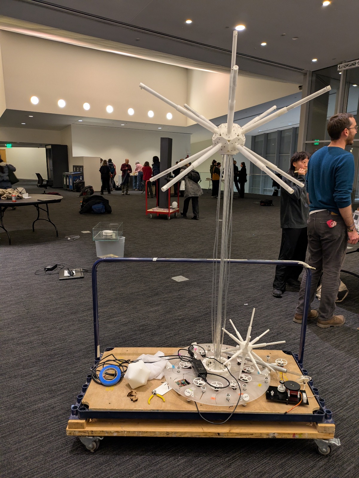
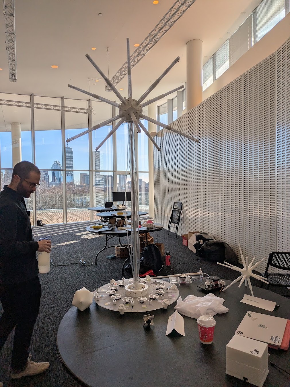
Final Presentation
Glowmorph was presented as an ambitious work-in-progress. Despite mechanical compromises, the system demonstrated responsive motion, proximity sensing, and variable amplitude control across the remaining motors.
Final Reflection
I think that the project was a testament to imposing too many constraints at a time. Between the skin, the motors, the sensors, the lights, etc. The project could not meaningfully exist in a partially built state behavior, structure, electronics, and power all depended on one another. In retrospect, this made the system fragile under time pressure. While a more conservative spiral development might have reduced risk, I chose an ambitious, tightly coupled build to test the limits of my fabrication, integration, and debugging skills. The result is imperfect, but deeply instructive. Glowmorph taught me where robustness actually lives not in ideas or simulations, but in interfaces, tolerances, and power paths. I don't necesarily have any regrets, I am happy to have really pushed myself, and I look forward to advancing this design and updating this page soon!
Failure & Iteration Log
- Servo power supply provided adequate voltage but insufficient current.
- Cable drum geometry allowed unspooling under load.
- Two servo motors failed late due to brownout or mechanical limits.
- Sensor wiring clearance was underestimated and required redesign.
- Lighting system deprioritized in favor of kinetic reliability.
Each failure directly informs the next iteration: redesigned cable drums, higher-current power delivery, improved strain relief, and clearer separation between mechanical and electronic subsystems.
Next Steps
The next iteration of Glowmorph will focus on mechanical robustness: a revised cable spool, stabilized power delivery, and full integration of the membrane skin. Lighting may remain secondary. At its core, Glowmorph is a kinetic sculpture.... light simply provided the excuse to build one.