Week 2 - Project Management, Computer Controlled Cutting, Version Control
Wrapping my Head Around Web Development
So I learned that web development is pretty challenging. That being said, I was really excited to throw myself in and get my hands dirty. Feeling empowered by our TA, Gert, I did a nose dive right into it. I started by trying to understand the concepts and logic of how version control systems work, what HTML means, why that's different than CSS, etc.
I was in over my head, and needed to hop onto what I playfully call: 'Youtube Academy'. After watching the first search result page of introduction videos to Git, I then turned to HTML and CSS. I can confidently say that a very talented communicator named Mosh helped me more than any other online educational resource. He has one separate video for Git and HTML/CSS basics. I find that following his examples and steps allowed me to confidantly build a pretty solid base website. Look! I even learned how to link a youtube video:
The workflow I've become comfortable with is entirely on Visual Studio Code (VSC). Initially I was using Git Bash for my command-line interface (CLI) for using Git on windows, while writing my website in VSC. After learning that I can create a terminal in VSC, it started seeming like the better option was to use it as a one-stop shop. I do know that VSC has a built-in Git interface, so that I can stage, commit, and push changes without typing commands, but that feels cowardly. Our TA, Camron Blackburn gave a really helpful recitation. I'll summarize for myself the most useful steps, which I still am trying to memorize and fully understand. The following is from her write-up.
Camron Blackburn's git & basic web development walkthrough
Once you are happy with your changes ALWAYS run the git status command.
This will tell you what files you have changed, how far ahead you are from
the remote repo, and what will be added to staging.
If you are happy with the files listed as “modified” or “untracked” from
git status, then run:

$ git add .

This will add all of those files to the staging area. If there are many
modified files and you only want to commit changes from a few, you can
specify which files to commit by calling them by name, for example:

$ git add index.html

Once you have files staged, you can commit them with:

$ git commit -m "type out commit message"

Finally, to push your changes to the global repository, run:

$ git push

If you are working with a team, you will need to pull changes from the
global repository to your local directory before you can push your changes.
To do this, run:

$ git pull
Introduction to Laser Cutting
I've been laser cutting pretty heavily for over a decade. That being said, my use case is typically architectural scale models which do not require the same precision of a mechanical part. Our lovely TA, Gert, walked us through how to use laser cutters. The following are my notes from our walkthrough:
1. Turn on main power 2. Make sure you are standing on pad 3. Turn on the laser cutter to the left switch 4. Add material to bed 5. Set the Z, make sure the center of material is 2 inches from the top of the material. 6. Open Rhino 7. Print to window. 8. Check the dimensionality to size of material through the properties menu 9. Set window, move to position, select only select d material 10. Set the speed, power and frequency. Use vector, not raster 11. Hit print, enter credentials
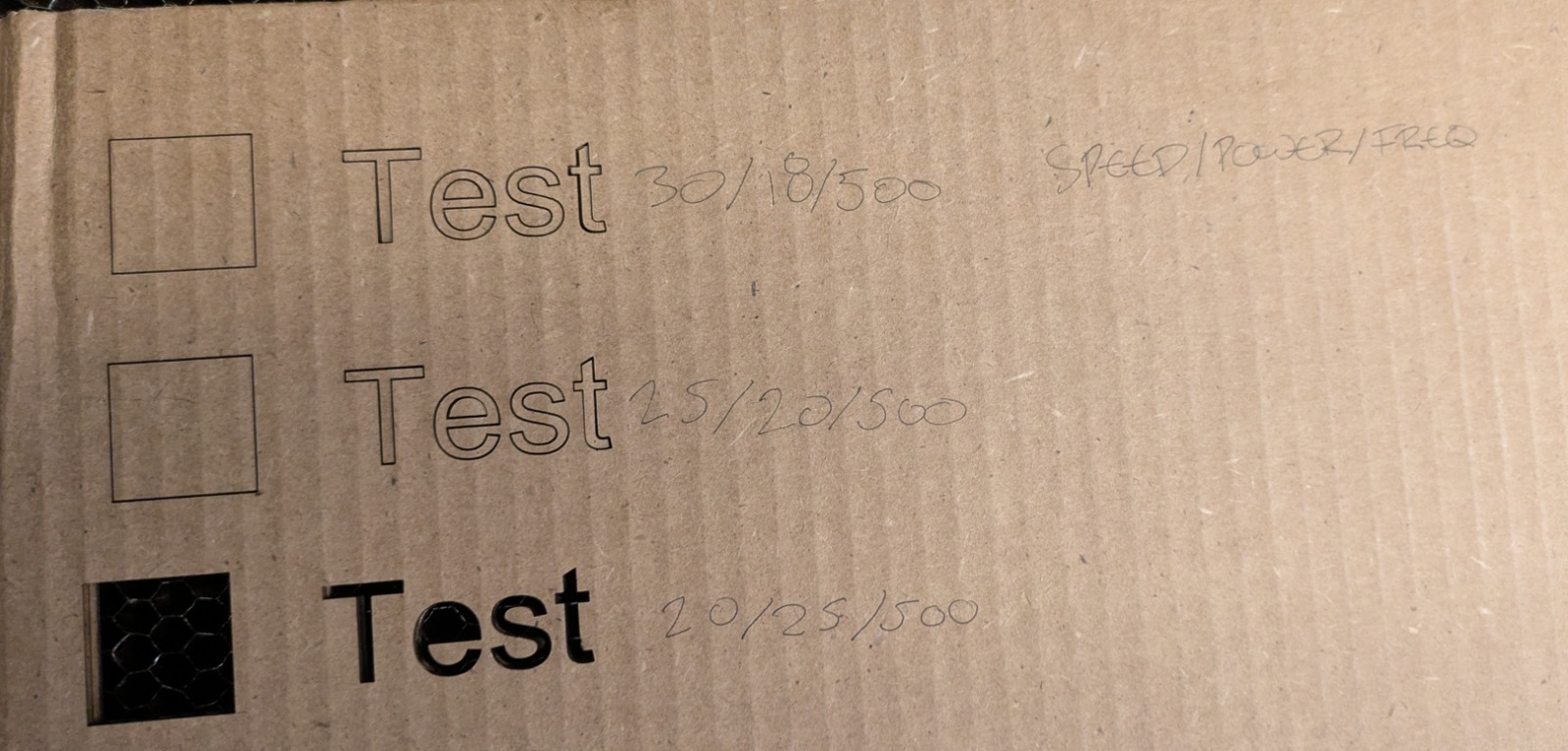
After the tour, I grouped up with whoever was present to test the correct laser settings for 1/4" cardboard as well as the tolerances for kerf. I worked with Anita, Stasya and Rodmehr first going through different power settings. The results are as follows, with the tested settings on the righthand side of the photo:
20 speed/ 25 power / 500 focus. Pass through twice with the same settings.
After configuring the correct laser cut settings, we went to test for kerf. Stasya came with an incredible website which will automatically make a tolerance test. You basically input the width, the amount of "steps" you want between the offsets of the tabs and the size of offsets as well. Link to the Kerf Test Generator
Kerf is the width of material that a laser removes when cutting. Basically when the laser passes through a material, it doesnt leave a perfect zero-width line - it burns or vaporizes a small strip of the material. That strip is called kerf. It really matters when cutting parts to fit together. It also slightly reduces the size of the remaining piece. In the past, I made pressure-fit assemblies, but I noticed with more brittle materials like plexi, this really matters. Worse still, it adds up as you move through a complex assembly.
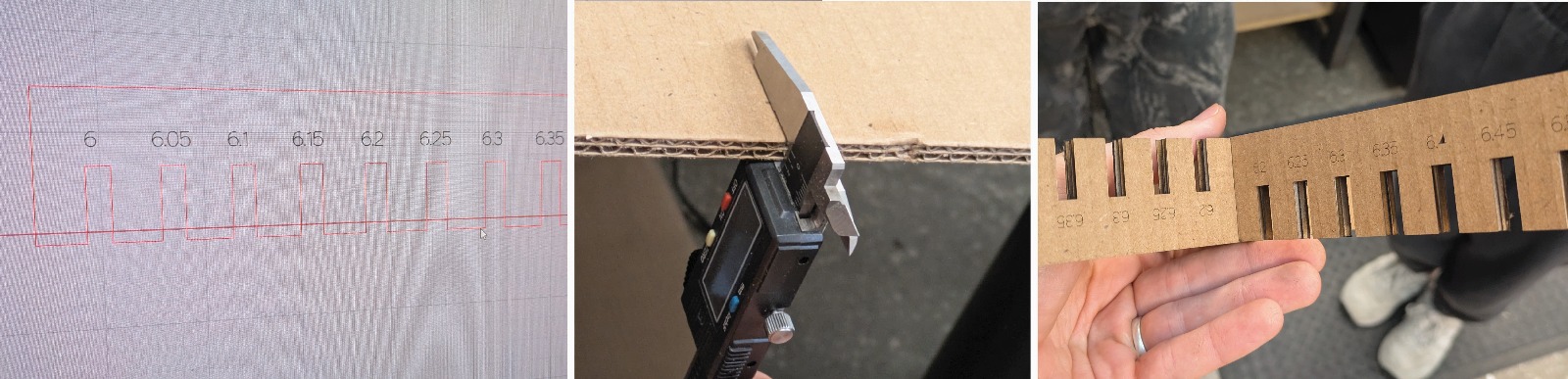
We measured the width of the material at 6mm, and found that .15 mm offset from the laser line is the best offset to accomodate for kerf.
Parametric Construction Kit
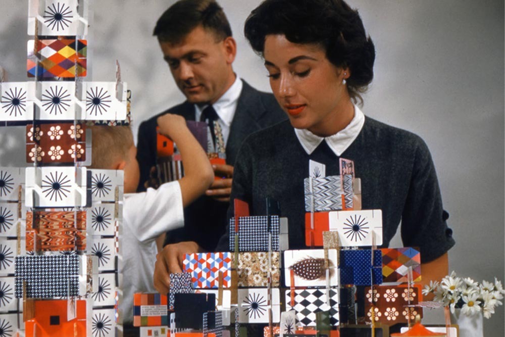
I have long been a lover of the work of the Eames. I like how playful they approach design problems. My reference for a construction kit was their 'House of Cards' from the 1950s. I always love how you can organize the deck into so many different playful configurations. I was keen on using this idea as a starting point and over designing it until it was something different while keeping this reference's configurability.
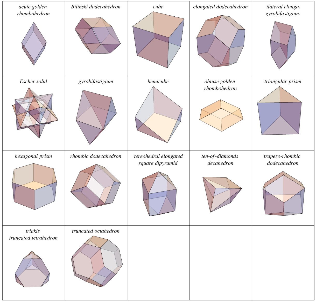
In general I'm pretty excited about space-filling polyhedrons. By applying the construction kit logic of the Eames card-stacking game to a space-filling polyhedron, each laser-cut piece becomes part of a modular, interlocking component that can be assembled in multiple configurations to form a various three-dimensional structures. Just as the Eames cards rely on simple, repetitive geometry to create complex forms, the polyhedral kit translates this principle into volumetric space, allowing the user to explore how individual planes or faces interact to fill space efficiently. This approach turns abstract mathematical forms into a tactile, playful system, making the principles of spatial tessellation and geometry physically accessible and experientially engaging. The following is from Wolfram Math World. https://mathworld.wolfram.com/Space-FillingPolyhedron.html
I began testing various possibilities in Rhino 3D space through explicit, rather than parametric, modeling. My first goal was to understand the constraints of the assembly system so I could better anticipate what kinds of aggregations might emerge from simple units or cells. Over time, I realized that it might be necessary to create a sub-unit cell with its own internal assembly before combining it with others to form larger aggregations.
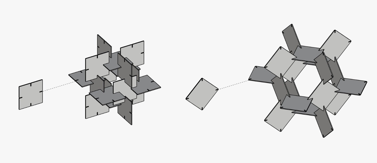
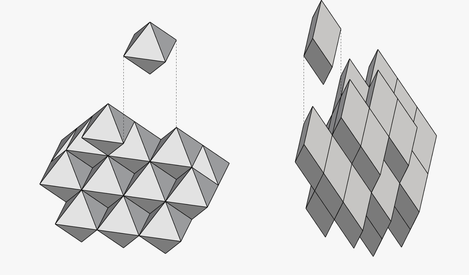
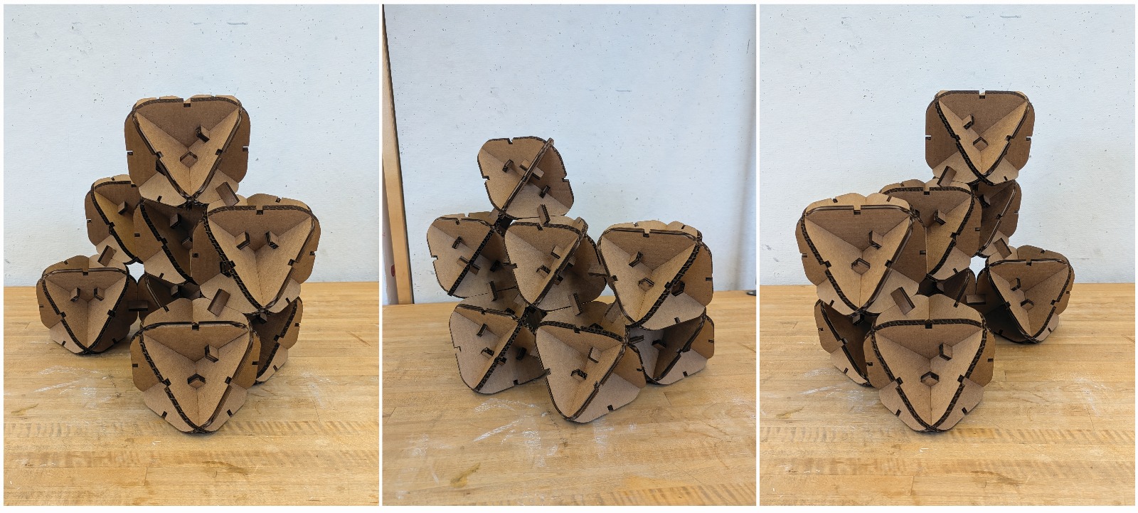
After shopping around for various polyhedra that could tesselate well in 3D space through just translation I settled on the octahedron. It seemed the perfect starting point because its eight triangles snap together in predictable ways, building complex, space-filling forms from a simple base. A playground to geometry—structured enough to hold together, but flexible enough to explore different arrangements.
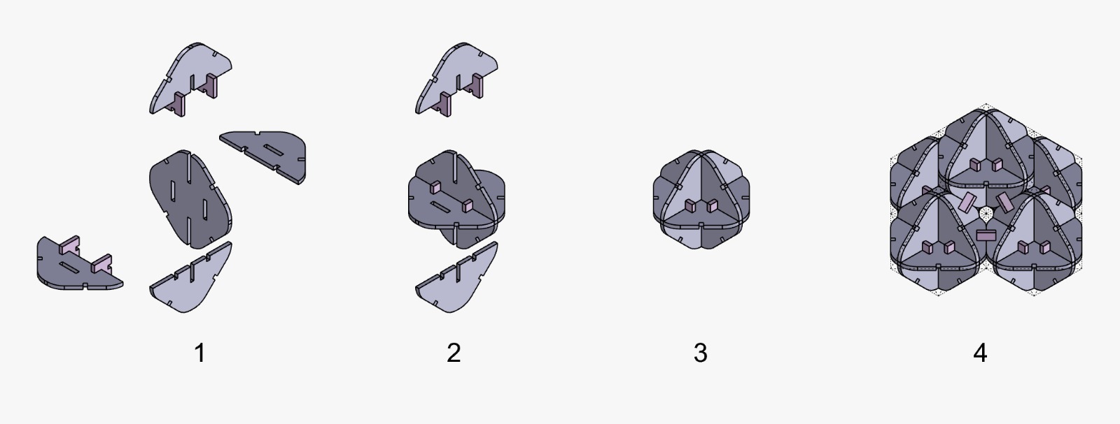
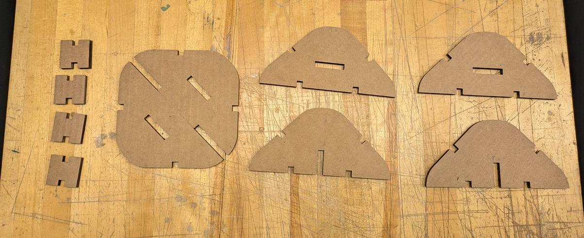
The real trick was figuring out how to pull off the 3-way plane intersection in each module. After realizing it would be impossible to rely on each plane as a single continuous piece, I opted for a press-fit locking mechanism. It was a gamble, but one that worked surprisingly well. Once I solved that part, the rest went smoothly. I ended up making nine prefabricated modules and linking them at their center points. The weak point of the design was definitely the center-point connection, which Id improve if I had more time and material. I tried to enclose space with my polyhedra and ended up with a small alcove. An interesting surprise was how the smaller structures reciprocated into a larger structure. I cant help but wonder: if I had two dozen more cells, what latent patterns might emerge?
Vinyl Cutter
Our fearless TA, Gert, also gave us great instructions for how to use the vinyl cutter. I'm really excited by its capabilities to cut softer materials that laser cutters would never be able to do. Basically, to use it, you just have to load the material roll, make sure that the motorized wheels are well within the bounds of that roll, and that the roll is extended well past the cutting area. After that you just run a test, and guage the depth of cutting so that it does not cut all the way through the material.
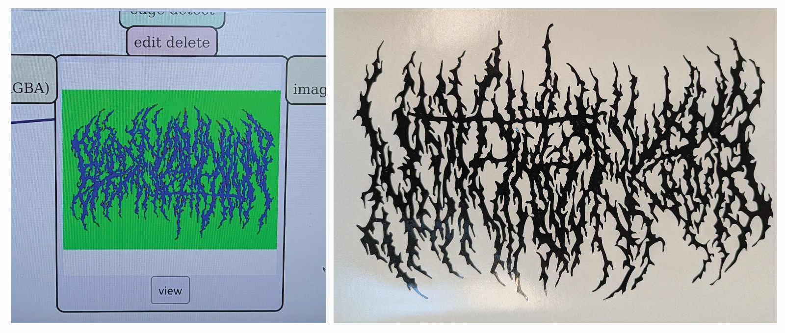
I wanted to push the capabilities of shape complexity and so i settled on one of my favorite band logos. It's from a progressive metal group called 'Blook Incantation'. Highly recommend them! Anyway it came out pretty well. I used a pressure setting of 90, which lightly etched the paper backing, then I was able to peel out the small sticker fragments with the tweezers.
Takeaways & Shout Out
- Takeaways: I learned that even when I feel over my head, breaking problems into smaller steps and using tutorials can build confidence. Understanding the logic behind tools like Git and version control makes collaboration and personal projects much smoother.
- Takeaways: Precision matters, even with tools I thought I knew well. Testing and calibrating (laser cutter, kerf adjustments) prevents mistakes in final assemblies.
- Shout Out: Huge thanks to our TAs, Gert and Camron, for making complicated workflows accessible.