Week 3 - Embedded Programming / Electronics
Introducing this week
For this week I used the QPad21 which was designed by Quentin Bolsee. The QPad21 is a custom ATSAMD21 board designed by Quentin. Full documentation is available on his GitHub: Quentin's GitHub
Hardware and Features
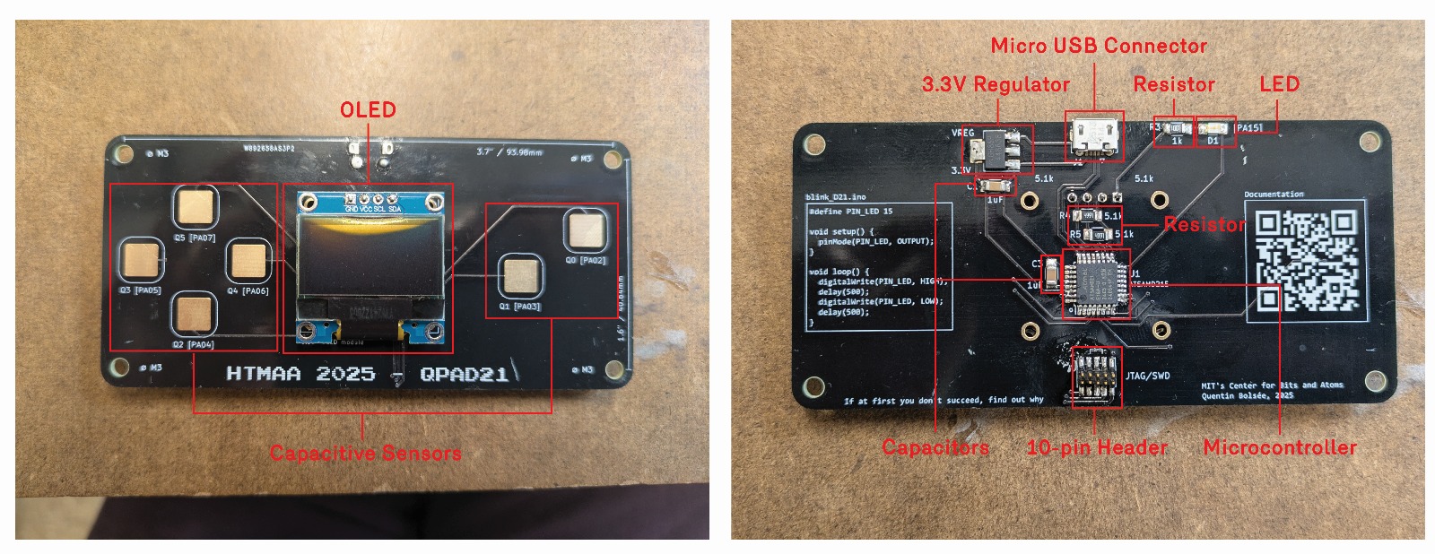
Back:
- Micro USB connector for 5V and ground connections.
- 3.3 Volt regulator (converts 5V to 3.3V for the microcontroller).
- (x2) Capacitors to store charge and reduce ripples.
- A resistor to limit current.
- Light Emitting Diode (LED).
- 10 Pin header for programming.
- ATSAMD21E Microcontroller: a 32-bit ARM Cortex-M0+. Compared to the AVR, it has more memory, faster clock, more peripherals, and a heavier toolchain.
Front:
- OLED screen
- Capacitive “button” sensors
Soldering and Assembly
- USB micro-B connector (power + data)
- 3.3V regulator and capacitors (power conditioning)
- 10-pin SWD header (programming/debugging interface)
- Resistors + LED
- OLED
- Tools: soldering iron, flux, tweezers, hot air, solder gel
- Verification: check continuity with a multimeter and ensure regulator outputs 3.3V when USB is plugged in.
Arduino SAM Tutorial
Install the Core:
-
In Arduino IDE → Settings → Additional Board Manager URLs → add:
https://raw.githubusercontent.com/qbolsee/ArduinoCore-fab-sam/master/json/package_Fab_SAM_index.json - Open Boards Manager, install Fab SAM core.
- In Tools → Board, select your chip (e.g., SAMD21E17 = Generic x21E).
Bootloader:
- Burn bootloader (first time only): Connect CMSIS-DAP programmer (e.g., Atmel ICE, Seeed XIAO). Select board + microcontroller + programmer → Burn Bootloader.
- Upload sketch: Use the regular Upload button.
- Upload with programmer (optional): if USB is disabled or upload is slow.
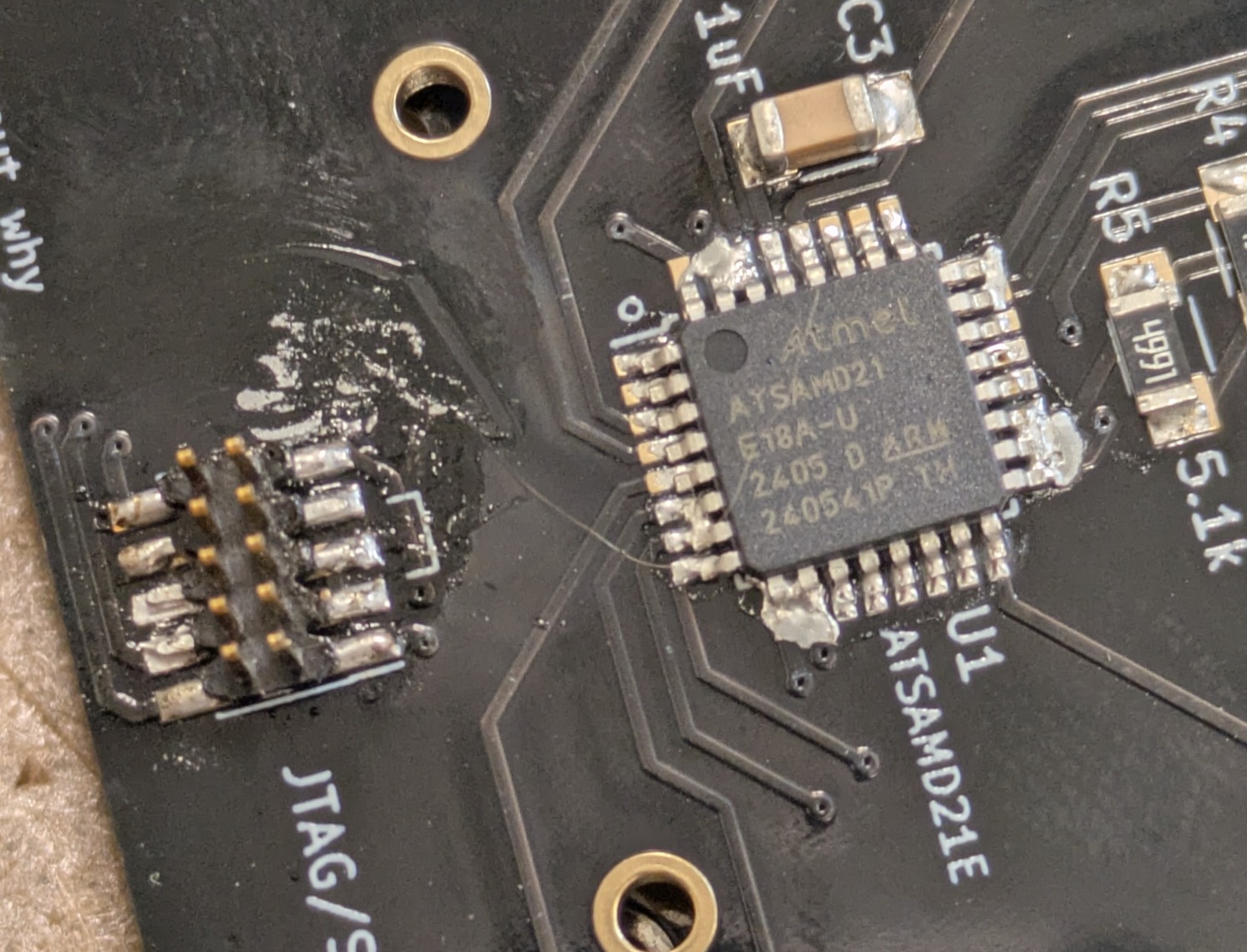
The image above shows my initial struggles with soldering. In general I was bridging everywhere.
Hardware Setup and Programming Takeaway
I chose the more challenging board to work with, partly because I have soldering experience and partly to push myself. The smallest pins, especially the USB connector, were the hardest to solder. I had to replace the USB connector multiple times due to unintended bridges. The process took longer than expected, and I relied on Anthony's help during office hours. In the end, we verified continuity with a multimeter, confirming correct connections. Once the hardware was set up, I moved on to programming.
Programming the Board with Demo Code
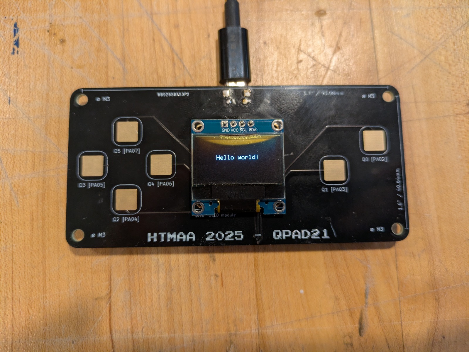
I had to retry loading the bootloader. At first, uploads kept failing even though the board showed up on the port. The next day I was able to re-burn the bootloader, which fixed the issue. Afterwards I ran demo code: Quentin's Example Code It was exciting to see a light turn on when I pressed a button! I also checked the OLED (still functional even after hot air damage). Then I moved on to writing my own code.
Programming the Board with My Own Code
Notes from Anthony’s presentation, plus Google searches and ChatGPT:
- void = returns nothing
- setup() = runs once at start
- loop() = runs forever
- digital = only ON or OFF (HIGH/LOW)
- analog = values in between
Example Arduino Code
Setup and Loop:
void setup() {
  pinMode(5, OUTPUT);   // LED
  pinMode(6, INPUT);    // button
}

void loop() {
  // if button pressed, LED on
  if (digitalRead(6) == HIGH) {
    digitalWrite(5, HIGH);
  } else {
    digitalWrite(5, LOW);
  }

  // blink LED 3 times
  for (int i = 0; i < 3; i++) {
    digitalWrite(5, HIGH);
    delay(200);
    digitalWrite(5, LOW);
    delay(200);
  }

  // keep LED on while button held
  while (digitalRead(6) == HIGH) {
    digitalWrite(5, HIGH);
  }
}
Explanations
setup()runs once: sets pin 5 as output (LED) and pin 6 as input (button).loop()runs forever.- If / else: button pressed → LED on, else off.
- For loop: blink LED 3 times with delay.
- While loop: keep LED on while button held.
Capacitive Touch Example
#include

#define PIN_LED 15       // LED pin
#define TOUCH_PIN 2      // touch pad
#define THRESHOLD 500    // sensitivity cutoff

Adafruit_FreeTouch touch_sensor = Adafruit_FreeTouch(
  TOUCH_PIN, OVERSAMPLE_1, RESISTOR_100K, FREQ_MODE_NONE
);

void setup() {
  Serial.begin(9600);        // debugging
  pinMode(PIN_LED, OUTPUT);  // LED pin
  touch_sensor.begin();      // start sensor
}

void loop() {
  int value = touch_sensor.measure();
  bool touched = value > THRESHOLD;

  if (touched) {
    digitalWrite(PIN_LED, HIGH);
  } else {
    digitalWrite(PIN_LED, LOW);
  }

  Serial.println(value);
  delay(50);
}
Blinking LED
#define LED_PIN 15  // onboard LED

void setup() {
  pinMode(LED_PIN, OUTPUT); // set LED pin as output
}

void loop() {
  digitalWrite(LED_PIN, HIGH); // turn LED on
  delay(500);                  // wait 0.5 sec
  digitalWrite(LED_PIN, LOW);  // turn LED off
  delay(500);                  // wait 0.5 sec
}
Takeaways & Shout Out
Takeaways: Soldering small components pushed both my patience and precision. Working through multiple bootloader retries reinforced the importance of debugging systematically and asking for help when stuck. Do not suffer in silence!
Shout Out: Anthony for offering some crucial guidance during office hours. He helped me identify small mistakes quickly which helped me spend more time working code than troubleshooting. Thanks!