Week 6 - Electronics Production
Group Assignment:
-
Characterize the design rules for your in-house PCB production
process
- Submit a PCB design to a board house
This week, we explored PCB fabrication using the Modela milling machine to understand the practical design limits of our in-house process. We characterized design rules such as trace width, spacing, and drill tolerances, and applied them to produce a functional PCB design ready for submission to a board house.
Using this mill file as a base, we found that 0.015 inches is the minimum trace width the Modela can process with a 1/64" end mill bit. Narrower traces either peel off the page or, in the case of a 'milled out' gap, are at the limit of being correctly registered in the CAM software. After testing and validating the PCB, we submitted the design to a board house for professional fabrication. This summary highlights the interaction between digital design, physical constraints, and precision manufacturing. Additional reflections, images, and step-by-step details will be provided on our shared web page.

Gert showing us how to use the modela mill
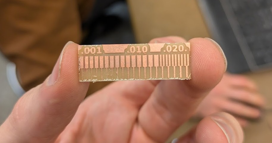
Tolerance test
Printed Circuit Board Milling
As a complete newbie to PCB design, PCB stuffing, coding, what have you, I wanted to start really simple. Using last week's design of an RGB LED light that switches colors depending on what switches you throw on. One would be Red, one Blue and one Green. This would affect a LED somewhere else on the board. Simple right?
A (deceptively unsimple for my skillset) RGB Switch
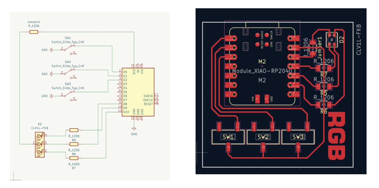
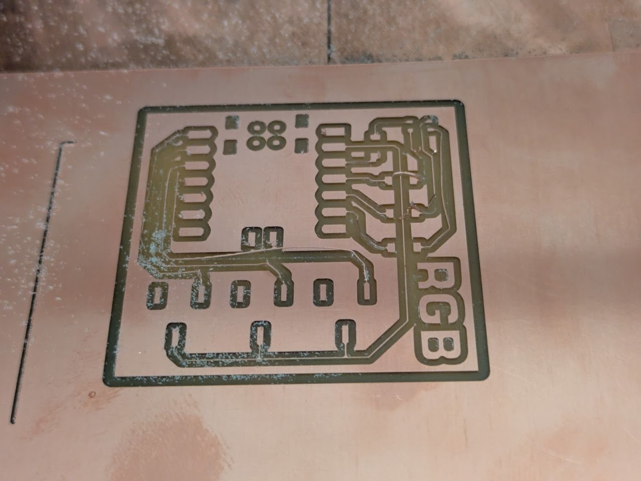
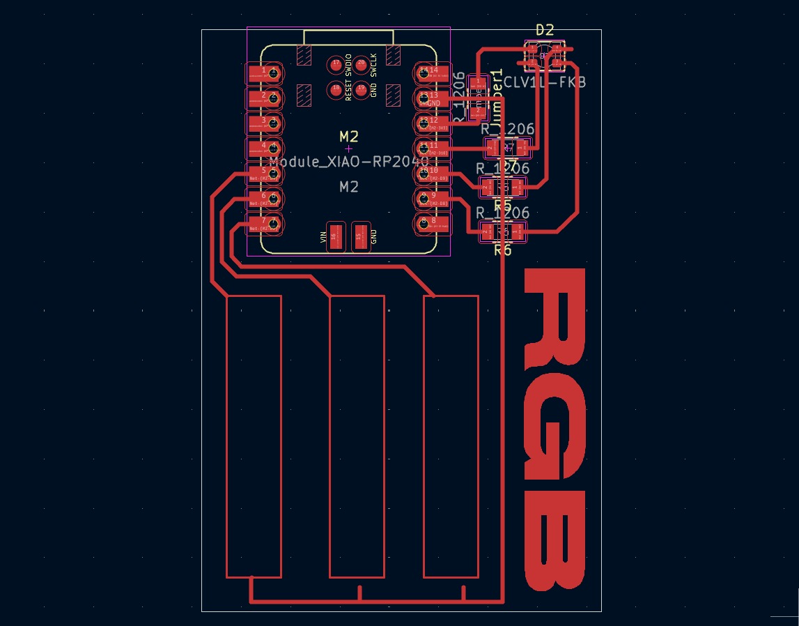
Schematic and Fabrication of my PCB

Tracing file for all the connections of my RGB board
The Problems Begin
OK so group project happened, I was excited to start milling my own board! Earlier in the week I went to two walkthroughs of the Modela SRM-20. But when I show up, 1 of the 2 PCB mills is already down. That's ok, I'll just wait in the queue. No biggie. I left myself plenty of time to design, build, program and debug this week. Immediately I see people experiencing errors with the Modela SRM-20. I would say 9/10 problems are with the interface between the PC and machine. There are two commands to punch into terminal in the JS folder. No indication of which one is the correct one on the Architecture Shops Website. Trial by fire, sure. There was a diagram that was kind of helpful.
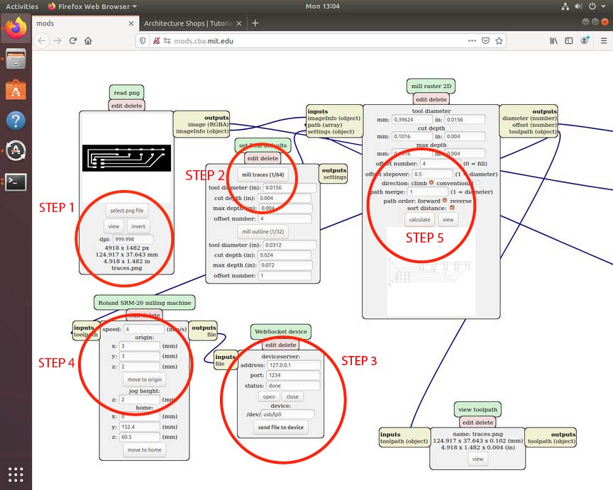
I found that you need to constantly close the firefox explorer, the terminal and shut off the Modela cutter. Then you need to do the following:
- Turn the mill on. It *should* home if you're lucky. That's when you open up the collar on the mill and put in the 1/64. Then tighten it.
- Upload - trace first - an image exported from Quentin's gerber2img.
- Hit that 'mill traces 1/64'. Begin saying prayers to your relevant god(s)
-
Right click inside of the JS file, and make sure to paste the second
of the two provided (for some reason) commands. As of today 10.13.2025
it is this one:
node deviceserver.js ::ffff:127.0.0.1 1234
- Press open on the WebSocket script element.
- Set the home, play with the Z so that the bit doesnt smash into the copper plated plastic board.
- Unscrew the collar, pull down the end mill so that its lightly pressing into the material. Tighten.
- Hit that 'calculate' in the mill raster 2D
- Press 'send file to device' in 'WebSocket Device script'. There is a 15 percent chance of it working. If it doesn't work go back and start all the way at the beginning.
Why is it so finicky? if a mouse farts in the nearby room it might disturb the machine. It's high strung, you're high strung, everyone is taking way too long to get the only machine working. I am usually excellent at this, but last night I spent 2 hours trying to get a simple board milled. Read on.

The Horrors Persist, but so do I
Fail 1
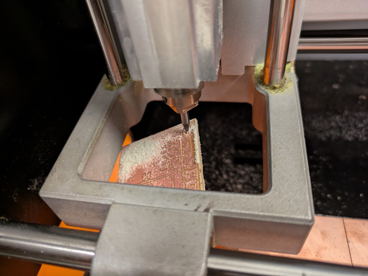
The first board went relatively ok. When I went to cut the outline 1/32 path, unfortunately it pulled off the spoil board. I used plenty of tape and I applied tons of pressure but maybe the spoil board was over-spoiled.
Fail 2
Next board was good. When I went to cut out the board with the 1/32 end mill, the toolpath was offset inwards. Looking over the PNG, I realized that the issue was in the gerber to png application. You need to select 'Fill Edge Cut'. OK new board.

Fail 3
whoops, board went ok, but then the pin holes were cut way too wide, no idea why. Also there should not be pin holes. I just put those on a different layer. New board.

Fail 4
The traces are really narrow. I assume that the 1/64 end mill that I was using was damaged. It's ok. I'll just run another one. At this point, who cares!
Fail 5
I see the curse has not yet been lifted. No idea why but the board lifted again. Once again, plenty of tape. Maybe the heavens have it out for me.

Not Fail 6
This board was finally ok! time to 'stuff' it.
Printed Circuit Board 'Stuffing'
Finding the parts and laying out components
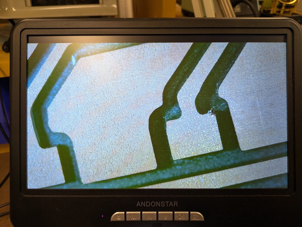
First I had to closely inspect the pathways to make sure that there were no bridges caused by frayed edges or metal splinters connecting paths that were not supposed to connect
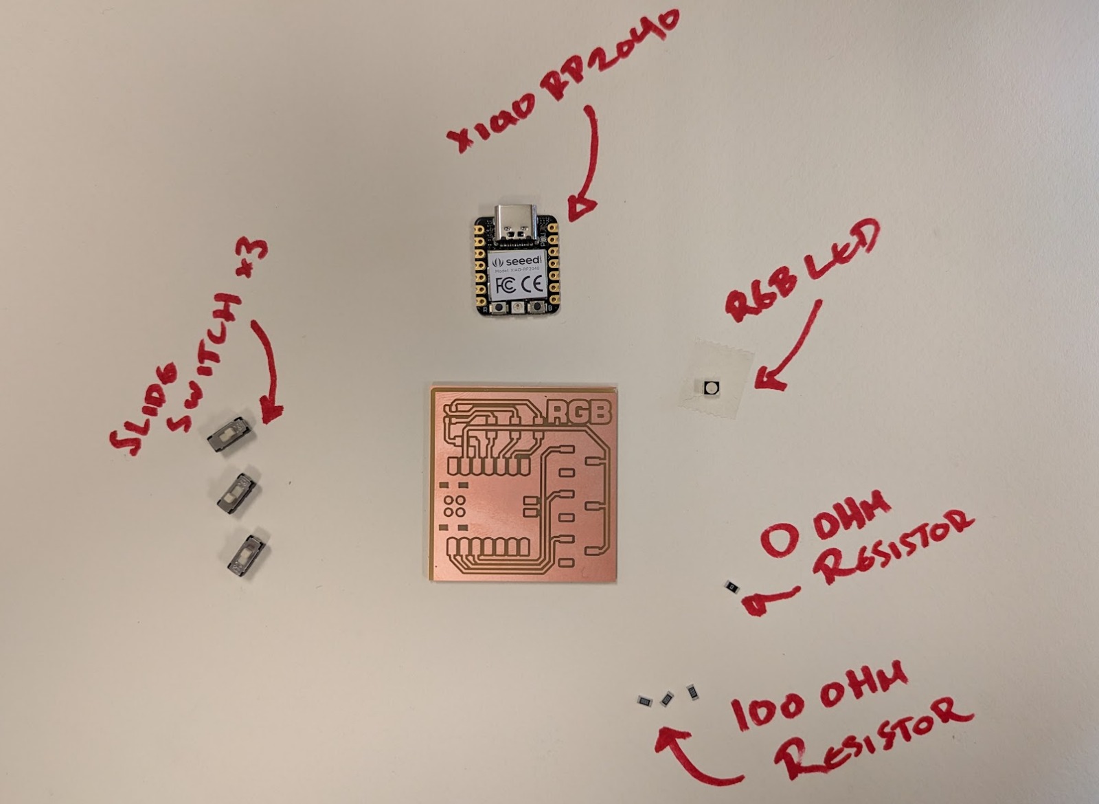
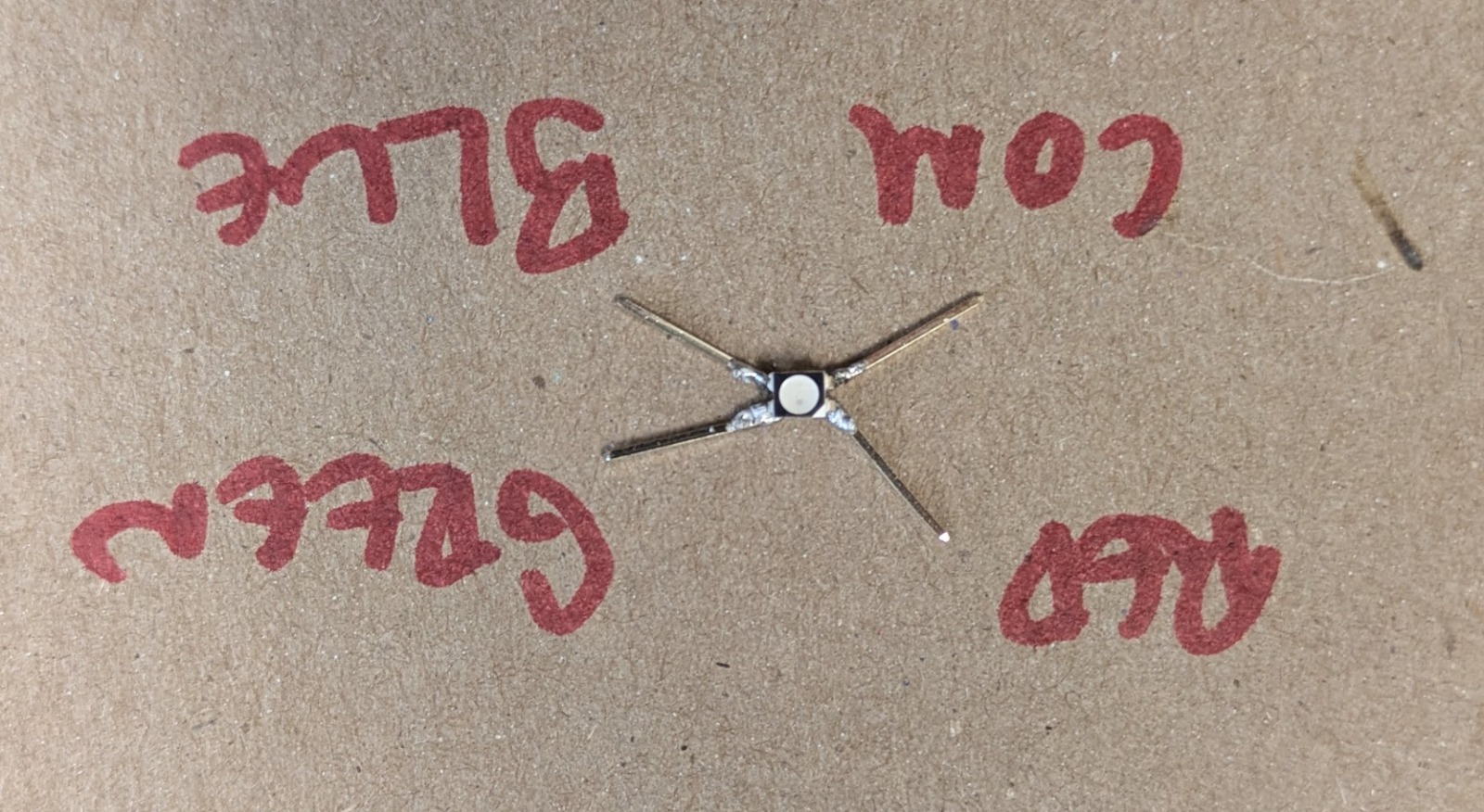
Next up, I needed to make sure I had the correct inventory of parts. Above is showing a backing paper with the relevant parts labeled.
Selecting the correct resistors
In order to select the correct resistors, I had a little bit of issue. I needed to look up the RGB LED that I was feeding to make sure I did not overwhelm the power requirements while not over-resisting where the light would not even be visible
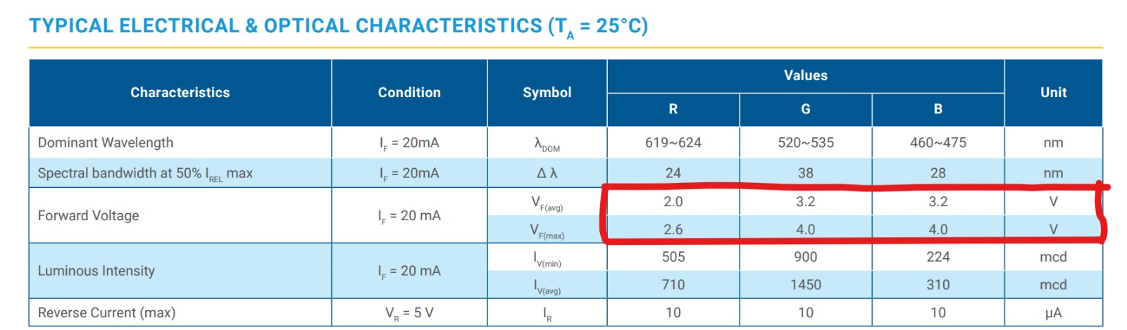
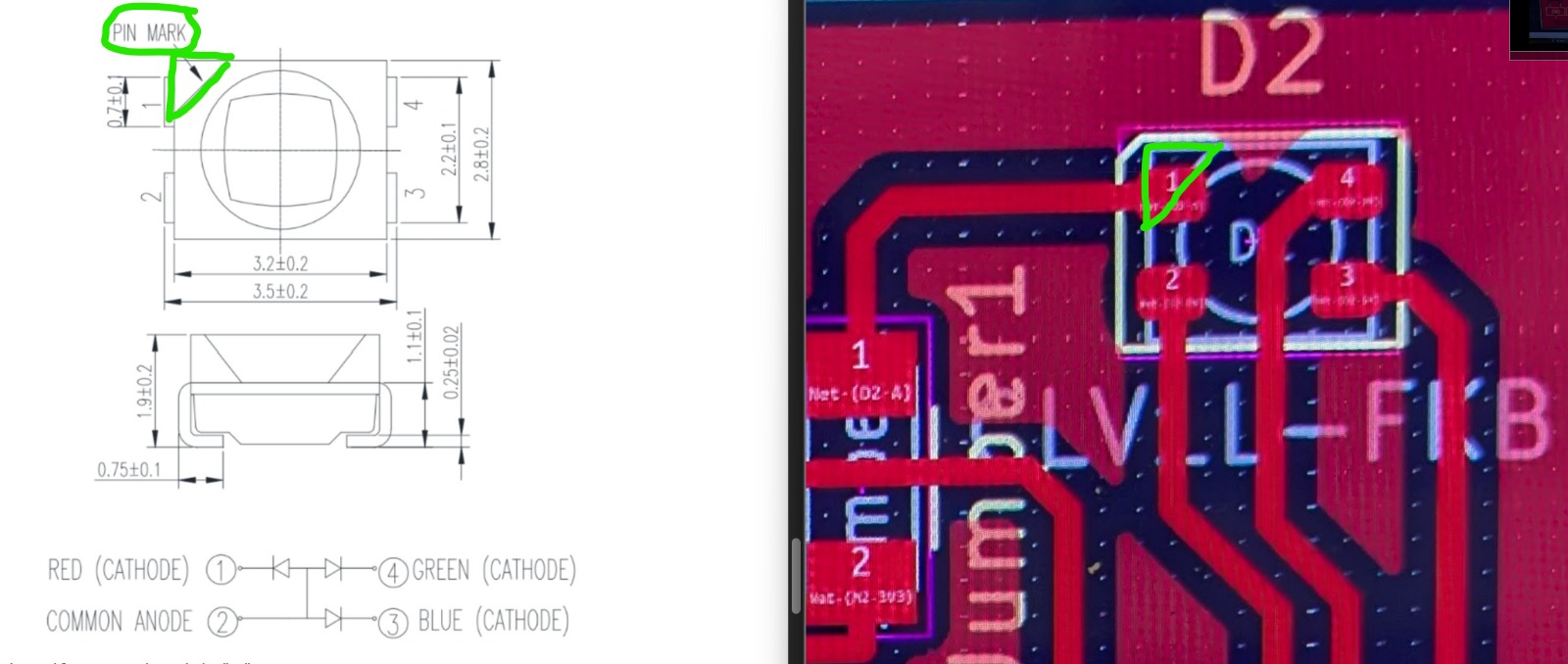
According to the data sheet for the LED - the CLV1A-FKB: PLCC4 3 in 1 SMD LED - I needed to identify the forward voltage of the red, green and blue diodes.
Calculating Resistors for the RGB LED on the XIAO RP2040
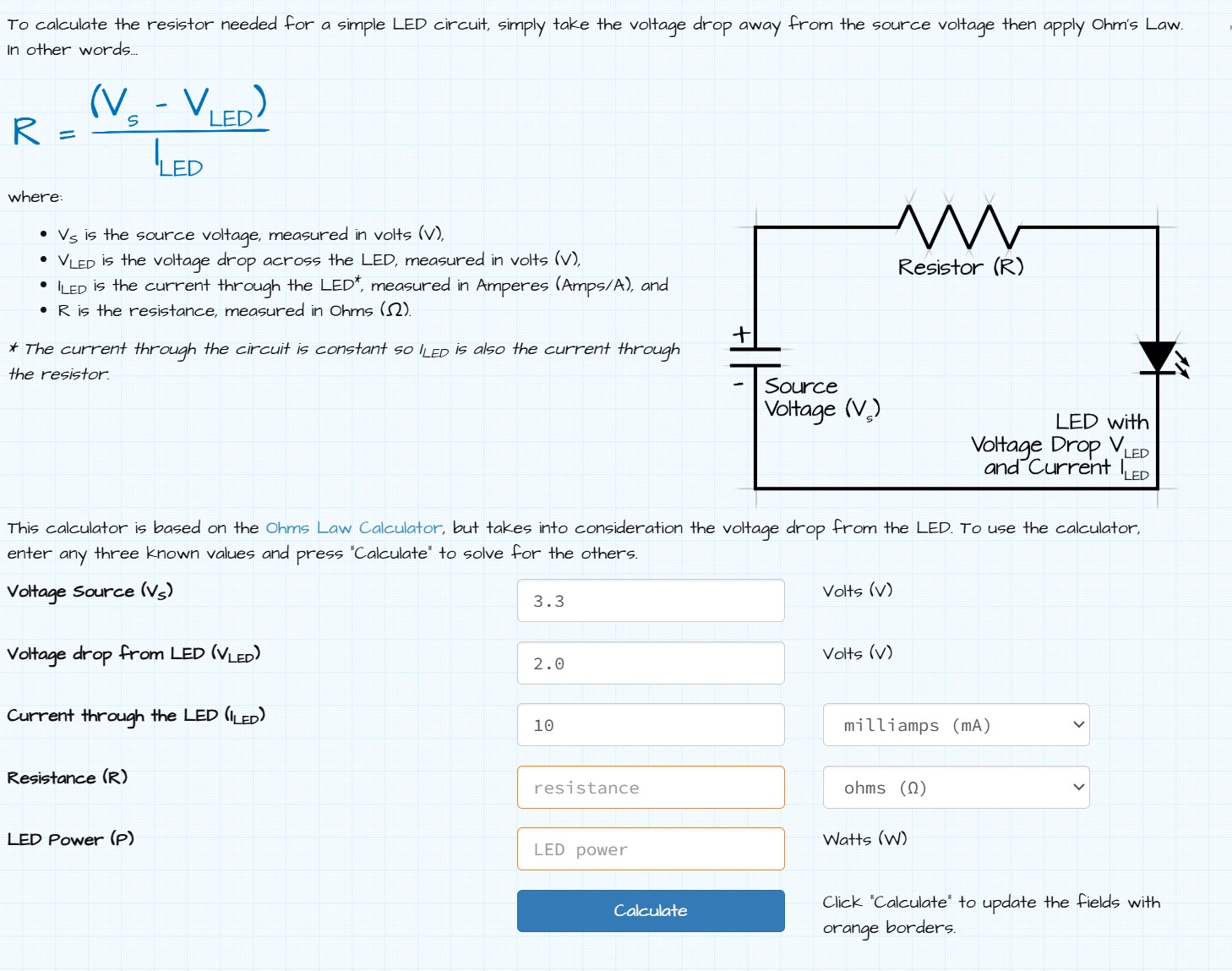
To safely use the CLV1A-FKB RGB LED with the Seeed XIAO RP2040, I needed to calculate the correct series resistor for each color. The LED datasheet specifies the forward voltage for each diode (Red: 2.0 V typical, Green: 3.2 V typical, Blue: 3.2 V typical) and a forward current of 20 mA.
The XIAO RP2040 GPIO pins operate at 3.3 V and are limited to around 15 mA per pin for safe operation. Because of this lower voltage and current limit, I could not drive the LED at the full 20 mA typical current without risking damage to the board.
Using the Ohm’s Law LED resistor calculator, I applied the formula:
R = (Vsupply − VF) ÷ IF
Where Vsupply is the GPIO voltage (3.3 V), VF is the forward voltage of the LED, and IF is the desired current (I chose 10 mA to stay safe). This gave the following recommended resistances:
- Red LED: (3.3 V − 2.0 V) ÷ 0.01 A ≈ 130 Ω → safe and bright
- Green LED: (3.3 V − 3.2 V) ÷ 0.01 A ≈ 10 Ω → very dim, barely works from GPIO
- Blue LED: (3.3 V − 3.2 V) ÷ 0.01 A ≈ 10 Ω → very dim, barely works from GPIO
Because the green and blue channels barely exceed the GPIO voltage, driving them directly from the XIAO is not ideal. For safe and bright operation, the LED should be powered by 5 V through a transistor or MOSFET, using the XIAO only to control the switches. This ensures all colors illuminate properly without exceeding the microcontroller's current limits.
'Stuffing'


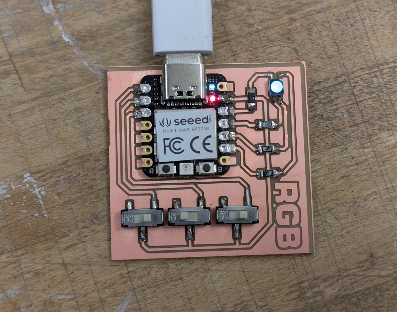
I found the digital magnification to be a complete asset to soldering my board together. A few things came up. I found the resistors as a bridge to work really well! And using a 0 ohm resistor was a great strategy to jumping over another line and looks pretty cool as well. The LED was hellish to solder, unfortunately. I think that I was completely underestimating what size it would be and it was really challenging to get a solder connection to all its four pins!

Final board. Now its time to trying some code out.
The Epic Debugging Journey
What should have been a straightforward coding exercise turned into a deep dive into the unpredictable world of debugging. The process taught me that sometimes, the problem isn't the code but the hardware's ghost in the machine.
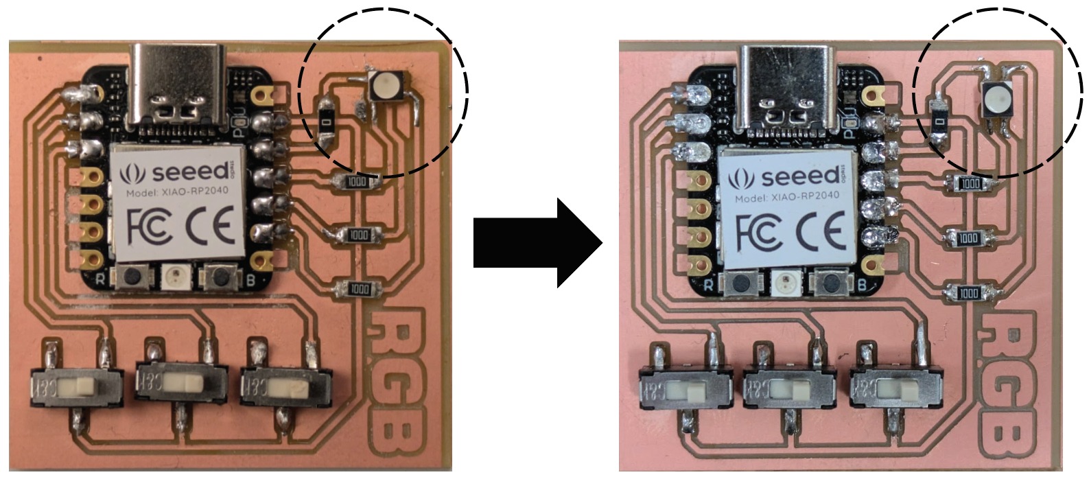
Resistance values are not correct


Above left is before, and above right is after
LED pins are not connected correctly
Still nothing was lighting up. I decided to double check over the CLV1A-FKB: PLCC4 3 in 1 SMD LED Data sheet to make sure that the Anode and Cathode plugs were correct. The footprint from the fab library is completely misleading. You can clearly see the anode in a different spot. It's not just an issue of notation on the LED component but is an issue with its footprint and geometry as well. I had to rotate the entire component and override the footprint in kicad in order to make an entirely new board as the LED has a rectangular ratio and not a square pin layout. I double checked with Griffin's github website where he had the correct orientation. I'm not sure why my library component from Fab was so incorrect, but it did cost me some time and my sanity.
I tried to fix the problem initially through some janky solution to see if I could get a LED light working correctly. Ultimately I decided it was somehow quicker to just redo everything from exporting gerber files to milling to stuffing.
Rotating the LED seemed to work! Unfortunately now, two issues still persist. One is that the colors of the LED do not change, the second is that then pins do not seem to change the readout of high or low. The debugging continues!
The Problem: A Board Stuck in "ON"
Code for Simple ON/OFF with Three Switches. The slide switches (D0, D1, D2) are controlling the corresponding Red, Green, and Blue LEDs (D10, D8, D9).
// --- PIN ASSIGNMENTS ---
const int RED_PIN = 10;
const int GREEN_PIN = 8;
const int BLUE_PIN = 9;

const int SW_RED = 0;   // Red Switch Input (D0)
const int SW_GREEN = 1; // Green Switch Input (D1)
const int SW_BLUE = 2;  // Blue Switch Input (D2)

void setup() {
  // Set LED pins as outputs
  pinMode(RED_PIN, OUTPUT);
  pinMode(GREEN_PIN, OUTPUT);
  pinMode(BLUE_PIN, OUTPUT);

  // Set Switch pins as inputs with internal PULLUP resistors
  // HIGH (1) = Switch Open, LOW (0) = Switch Slid to GND
  pinMode(SW_RED, INPUT_PULLUP);
  pinMode(SW_GREEN, INPUT_PULLUP);
  pinMode(SW_BLUE, INPUT_PULLUP);

  // Initialize all LEDs to OFF state (Common Anode: HIGH = OFF)
  digitalWrite(RED_PIN, HIGH);
  digitalWrite(GREEN_PIN, HIGH);
  digitalWrite(BLUE_PIN, HIGH);
}

void loop() {
  // Read the state of the switches
  bool redPressed = (digitalRead(SW_RED) == LOW);
  bool greenPressed = (digitalRead(SW_GREEN) == LOW);
  bool bluePressed = (digitalRead(SW_BLUE) == LOW);

  // Control Logic (If switch is slid/LOW, set LED LOW/ON)
  digitalWrite(RED_PIN, redPressed ? LOW : HIGH);
  digitalWrite(GREEN_PIN, greenPressed ? LOW : HIGH);
  digitalWrite(BLUE_PIN, bluePressed ? LOW : HIGH);

  delay(10);
}
Initial Hypothesis: Wrong Resistor Values
My initial Ohm's Law calculations were for a safe operating current, but they were too high for the Green and Blue LEDs to turn on at all with a 3.3V power source. I learned that for a Common Anode setup, high-value resistors can prevent current flow if the voltage drop across the LED is too high. My fix was to use a 100 ohm resistor for Red and a 25 ohm resistor for Green and Blue. I was told by other people that these values of resistors are not used, so I said I'd try to keep with 100 anyway, as a 0 ohm resistor would damage my board.
Hardware Failure Hypothesis: Short to GND
Even with the correct resistors, the LEDs stayed permanently on and the switches were unresponsive. Using the Serial Monitor, I confirmed that the microcontroller's input pins were stuck at a permanent LOW state, which is typically caused by a short circuit to Ground. The same issue was preventing the LEDs from turning off, as the short was holding their control pins at 0V.
Diagnoses Code 1: Switch Test (Serial Monitor)
// --- PIN ASSIGNMENTS (Switch Inputs Only) ---
const int SW_RED = 0;
const int SW_GREEN = 1;
const int SW_BLUE = 2;

void setup() {
  pinMode(SW_RED, INPUT_PULLUP);
  pinMode(SW_GREEN, INPUT_PULLUP);
  pinMode(SW_BLUE, INPUT_PULLUP);

  Serial.begin(115200);
  Serial.println("--- Switch Diagnosis Mode ---");
  Serial.println("Expected: 1 when open, 0 when slid.");
}

void loop() {
  int redState = digitalRead(SW_RED);
  int greenState = digitalRead(SW_GREEN);
  int blueState = digitalRead(SW_BLUE);

  Serial.print("Red: "); Serial.print(redState);
  Serial.print(" | Green: "); Serial.print(greenState);
  Serial.print(" | Blue: "); Serial.println(blueState);
  delay(10);
}
Anthony Saves the Day

Just when I gave up, I sent my work to Anthony who immediately noticed my error. The pins in the Xiao RP2040 are read differently in code. I updated my code following his advice to include 'D' before the digital pins. I feel silly how simple a mistake that was!
Updated Base Code
// --- PIN ASSIGNMENTS ---
const int RED_PIN = D10;
const int GREEN_PIN = D8;
const int BLUE_PIN = D9;

const int SW_RED = D0;   // Red Switch Input (D0)
const int SW_GREEN = D1; // Green Switch Input (D1)
const int SW_BLUE = D2;  // Blue Switch Input (D2)

void setup() {
  // Set LED pins as outputs
  pinMode(RED_PIN, OUTPUT);
  pinMode(GREEN_PIN, OUTPUT);
  pinMode(BLUE_PIN, OUTPUT);

  // Set Switch pins as inputs with internal PULLUP resistors
  // HIGH (1) = Switch Open, LOW (0) = Switch Slid to GND
  pinMode(SW_RED, INPUT_PULLUP);
  pinMode(SW_GREEN, INPUT_PULLUP);
  pinMode(SW_BLUE, INPUT_PULLUP);

  // Initialize all LEDs to OFF state (Common Anode: HIGH = OFF)
  digitalWrite(RED_PIN, HIGH);
  digitalWrite(GREEN_PIN, HIGH);
  digitalWrite(BLUE_PIN, HIGH);
}

void loop() {
  // Read the state of the switches
  bool redPressed = (digitalRead(SW_RED) == LOW);
  bool greenPressed = (digitalRead(SW_GREEN) == LOW);
  bool bluePressed = (digitalRead(SW_BLUE) == LOW);

  // Control Logic (If switch is slid/LOW, set LED LOW/ON)
  digitalWrite(RED_PIN, redPressed ? LOW : HIGH);
  digitalWrite(GREEN_PIN, greenPressed ? LOW : HIGH);
  digitalWrite(BLUE_PIN, bluePressed ? LOW : HIGH);

  delay(10);
}
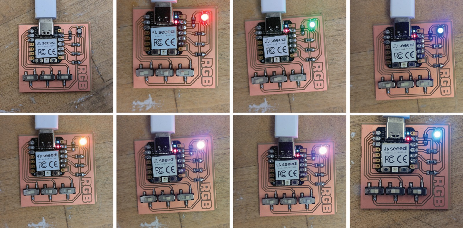
| Red | Green | Blue | Resulting Color |
|---|---|---|---|
| 0 | 0 | 0 | Off / Black |
| 1 | 0 | 0 | Red |
| 0 | 1 | 0 | Green |
| 0 | 0 | 1 | Blue |
| 1 | 1 | 0 | Yellow |
| 1 | 0 | 1 | Magenta / Pink |
| 0 | 1 | 1 | Cyan / Aqua |
| 1 | 1 | 1 | White |
I wanted to see the Serial Monitor output so I could see what’s happening in real time, as in which switches are pressed and which LEDs are on.
// --- PIN ASSIGNMENTS ---
const int RED_PIN = D10;
const int GREEN_PIN = D8;
const int BLUE_PIN = D9;

const int SW_RED = D0;   // Red Switch Input (D0)
const int SW_GREEN = D1; // Green Switch Input (D1)
const int SW_BLUE = D2;  // Blue Switch Input (D2)

void setup() {
  // Initialize Serial communication
  Serial.begin(9600);
  while (!Serial) {
    ; // Wait for Serial to initialize (optional on some boards)
  }
  Serial.println("System initialized. Waiting for switch input...");

  // Set LED pins as outputs
  pinMode(RED_PIN, OUTPUT);
  pinMode(GREEN_PIN, OUTPUT);
  pinMode(BLUE_PIN, OUTPUT);

  // Set Switch pins as inputs with internal PULLUP resistors
  pinMode(SW_RED, INPUT_PULLUP);
  pinMode(SW_GREEN, INPUT_PULLUP);
  pinMode(SW_BLUE, INPUT_PULLUP);

  // Initialize all LEDs to OFF (Common Anode: HIGH = OFF)
  digitalWrite(RED_PIN, HIGH);
  digitalWrite(GREEN_PIN, HIGH);
  digitalWrite(BLUE_PIN, HIGH);
}

void loop() {
  // Read the state of the switches
  bool redPressed = (digitalRead(SW_RED) == LOW);
  bool greenPressed = (digitalRead(SW_GREEN) == LOW);
  bool bluePressed = (digitalRead(SW_BLUE) == LOW);

  // Control LEDs (LOW = ON for Common Anode)
  digitalWrite(RED_PIN, redPressed ? LOW : HIGH);
  digitalWrite(GREEN_PIN, greenPressed ? LOW : HIGH);
  digitalWrite(BLUE_PIN, bluePressed ? LOW : HIGH);

  // Send serial output
  Serial.print("Red: ");
  Serial.print(redPressed ? "ON" : "OFF");
  Serial.print(" | Green: ");
  Serial.print(greenPressed ? "ON" : "OFF");
  Serial.print(" | Blue: ");
  Serial.println(bluePressed ? "ON" : "OFF");

  delay(200); // Small delay to make serial output readable
}
Capacitance RGB PCB
My original idea was to create an RGB light where R, G and B would be mapped to capacitance sensing. I was inspired by Quentin's board . I have run out of time, but I will aim to mill this shortly after class to see if it works.
It's a slight adjustment of my current switch configuration.


I had to overlay a few shapes in photoshop to break some of my design rules
Final Takeaways
- PCB milling requires extreme patience. Even small deviations in calibration can ruin hours of work.
- Always double-check component footprints—especially uncommon or multi-die LEDs like the PLCC4.
- GPIO pins are voltage-limited. If your LED won’t turn on, consider supply voltage and resistor sizing carefully.
- Debug systematically: separate switch inputs, LED outputs, and microcontroller logic to isolate failures.
- Document everything! Photos, measurements, and resistor values helped me track down multiple cascading failures.
Despite the horrors, I now have a working RGB switch board, and I feel much more confident handling SMD components, calculating resistor values, and debugging hardware-software interactions.