Week 7 - Computer-Controlled Machining
Past Experience, and Focus for this Week
I have CNC'd a lot of projects in my 5 years of school and 7 years of practice, and so I know really well that every shop has different cam software, different machines, and general workflow. I wanted to treat this week as a way to dial in the workflow here. Rather than spend a crazy amount of time desgining an intricate creation, I wanted to hone in the how-to of milling here. On one hand I want to "make something big", but I also dont like waste, and I suspect that's where peoples 'big' projects will end become.
Walk Through and Tolerance Tests
We met up with Chris to get introduced to our machine and CNC set-up. We have an Onsrud 3-axis router in N51-160, with a 48x96" table and 6" Z clearance. Refer to the Architecture Shops Website for more information. He explained the following workflow:
The workflow starts with preparing clean CAD geometry correct scale, proper zero, and simplified to only the cut areas. Once geometry is set, material is secured to the vacuum table (or screwed/clamped if porous or warped). In Mastercam, toolpaths are created for roughing, pocketing, and finishing with end mills sized ⅛″–½″. The Onsrud has a 12-tool carousel and runs best with flat, non-porous sheets. Before cutting, the material is aligned and the origin zeroed in X, Y, and Z. A quick “air pass” ensures no collisions. During cutting, it’s important to monitor hold-down and chip evacuation. Once done, the part is released, edges cleaned up, and the bed vacuumed for the next user.
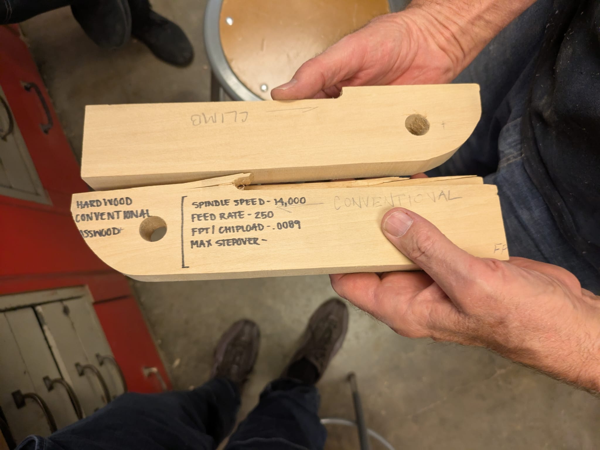
The direction of milling is really important. Chris explained that when doing interior cuts, the mill typically moves counter clockwise, whereas when cutting out outer figures the mill should move clockwisie.
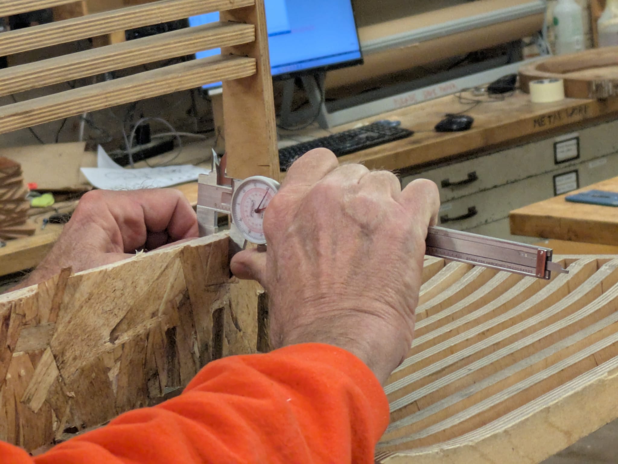
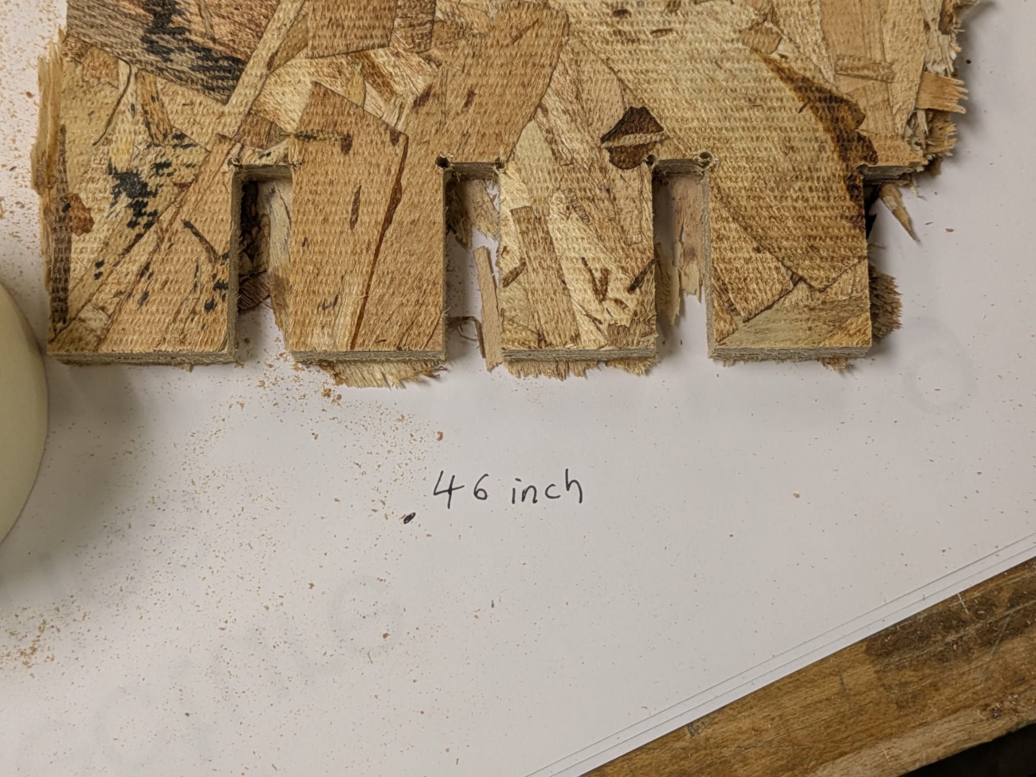
We measured the OSB board to be a .46 inches deep. When trying the tolerance test, we found that .45 to be the best fit - snug but not too tight that you need to mallet it together. We were told that before every job, one should always run a test. Not only is there a nominal material difference from the stated dimension, but humnidity can fluctuate the thickness pretty significantly.
OSB Planter
Unfortunately, my plant in my room has gotten so large in its pot that it does not fit on the window sill. I wanted to use this week to make a booster so that she can get sunlight again!
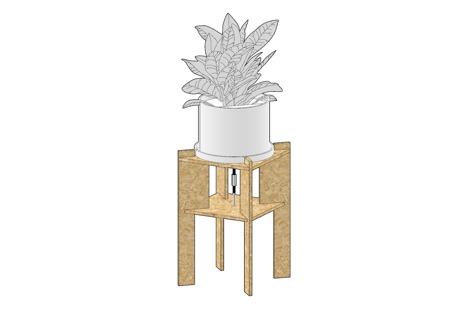
The idea was to keep it simple. 6 milled pieces, slotted together and kept in compression by using two male bolts and a coupling nut to tighten everything together to create a structurally rigid package.
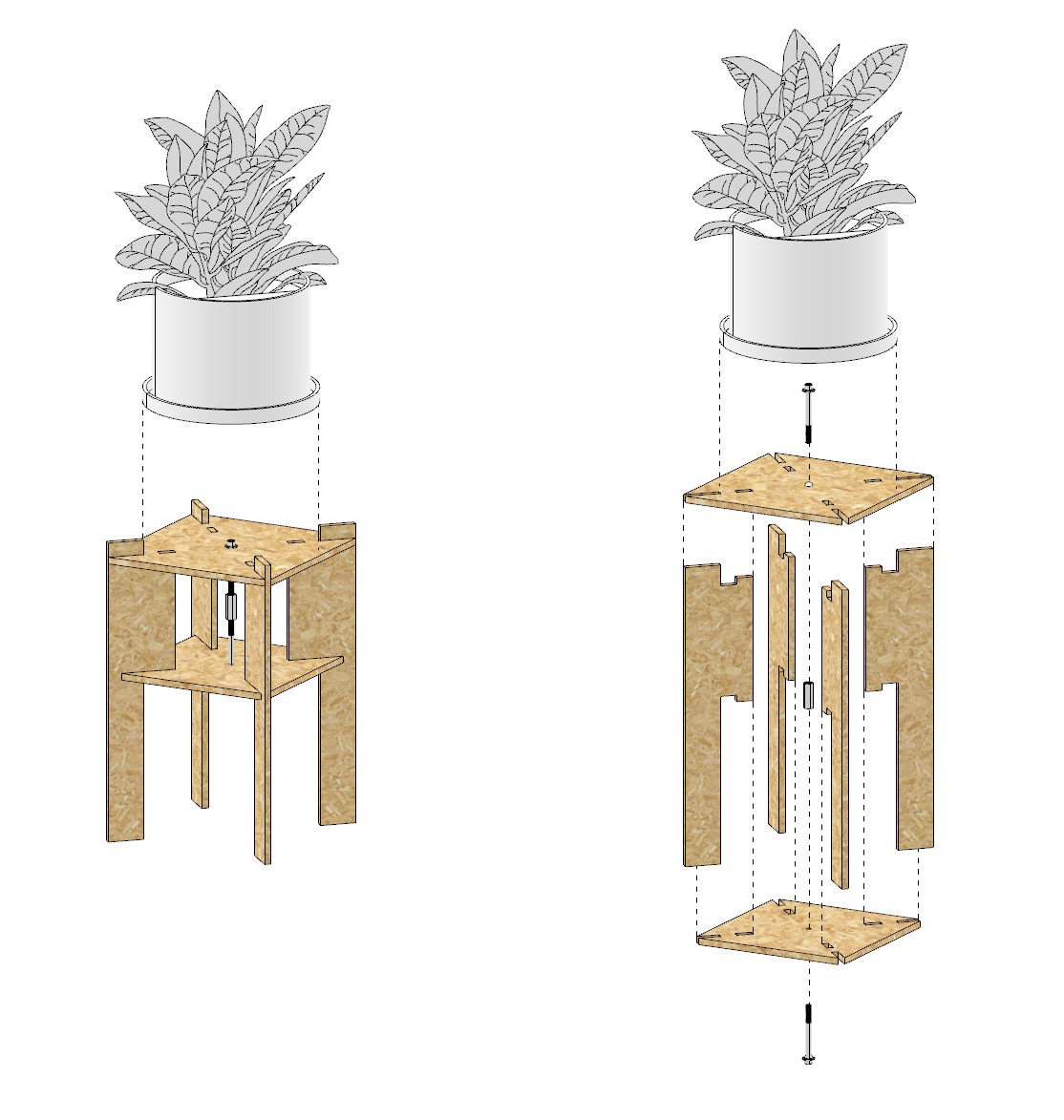
Assembly diagram showing the parts. I'd rely on using additional hardware, but i thought that was the beauty of the piece, a singular mechanical connection that is clearly expressed.
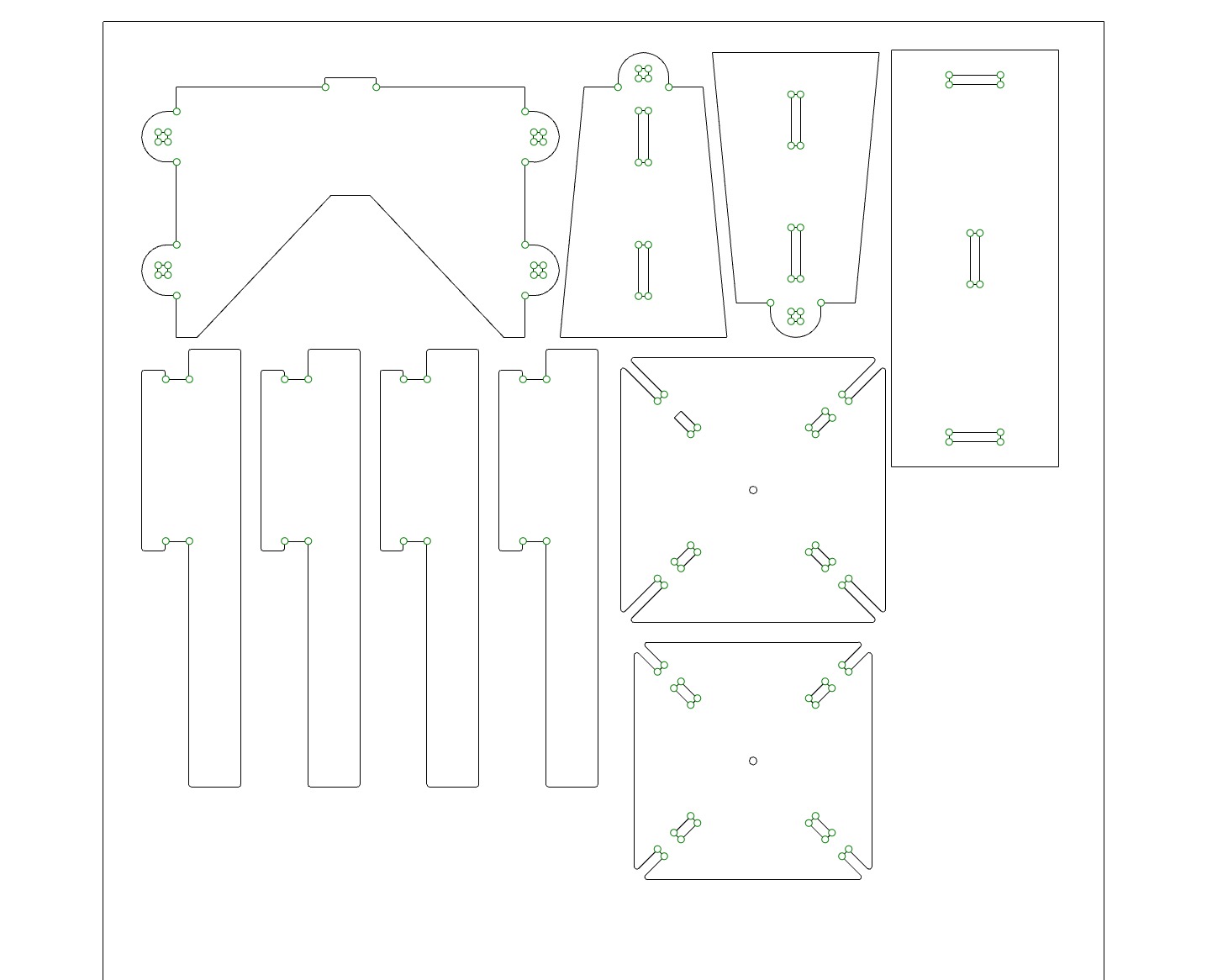
Feeling the time crunch of an incoming weekend where there will be no milling, I opted to share stock with Geoffery. Above is the layout.
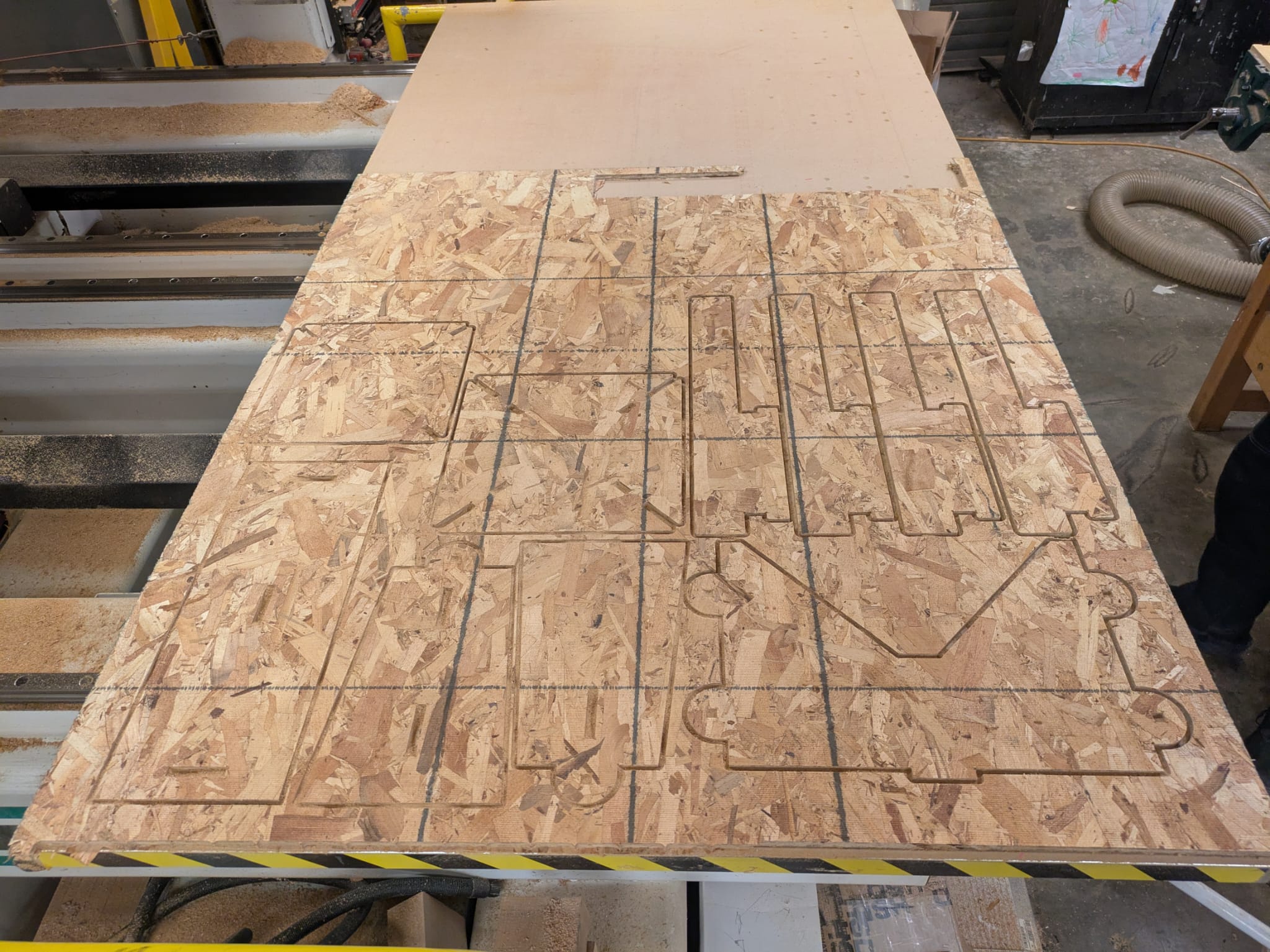
The sheet right after milling
Above are my parts right after extracting them from the mill job. Chris insisted on using an onion milling technique to both preserve the spoil board as well as to keep pieces from moving after cutting.
Corners were drilled in order to prevent the fillet from the tool path.
"U" or "H" frame Open Baffle Speaker
Background
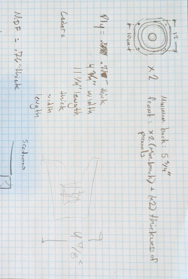
I'm headed up to NYC this weekend to fabricate a version 1.0 of an open baffle speaker that I've been designing with two friends. I thought it would be fun to try rapidly making a funky speaker experiment using some of the milling techniques we discussed in the class with some of the engineering principles. Open-baffle speakers are interesting. They challenge the conventional box approach to loudspeaker design. In an OB, the drivers are mounted on a flat baffle without an enclosure behind it. Sound radiates both forward and backward, rather than being trapped and reflected in a box. In a box, the rear wave is absorbed or redirected whereas in OB design, the rear wave is allowed to radiate freely into the room, creating a dipole radiation pattern (figure 8-sound field). The benefits are Natural / Open Soundstage, minimal box coloration, fast and dynamic transient response and they allow for sculptural experimentation.
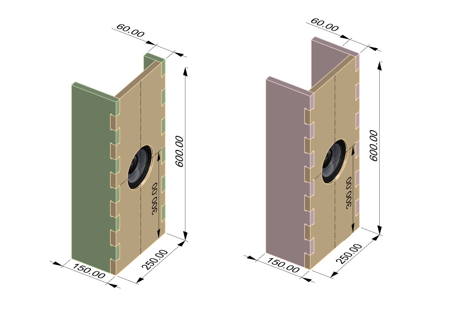
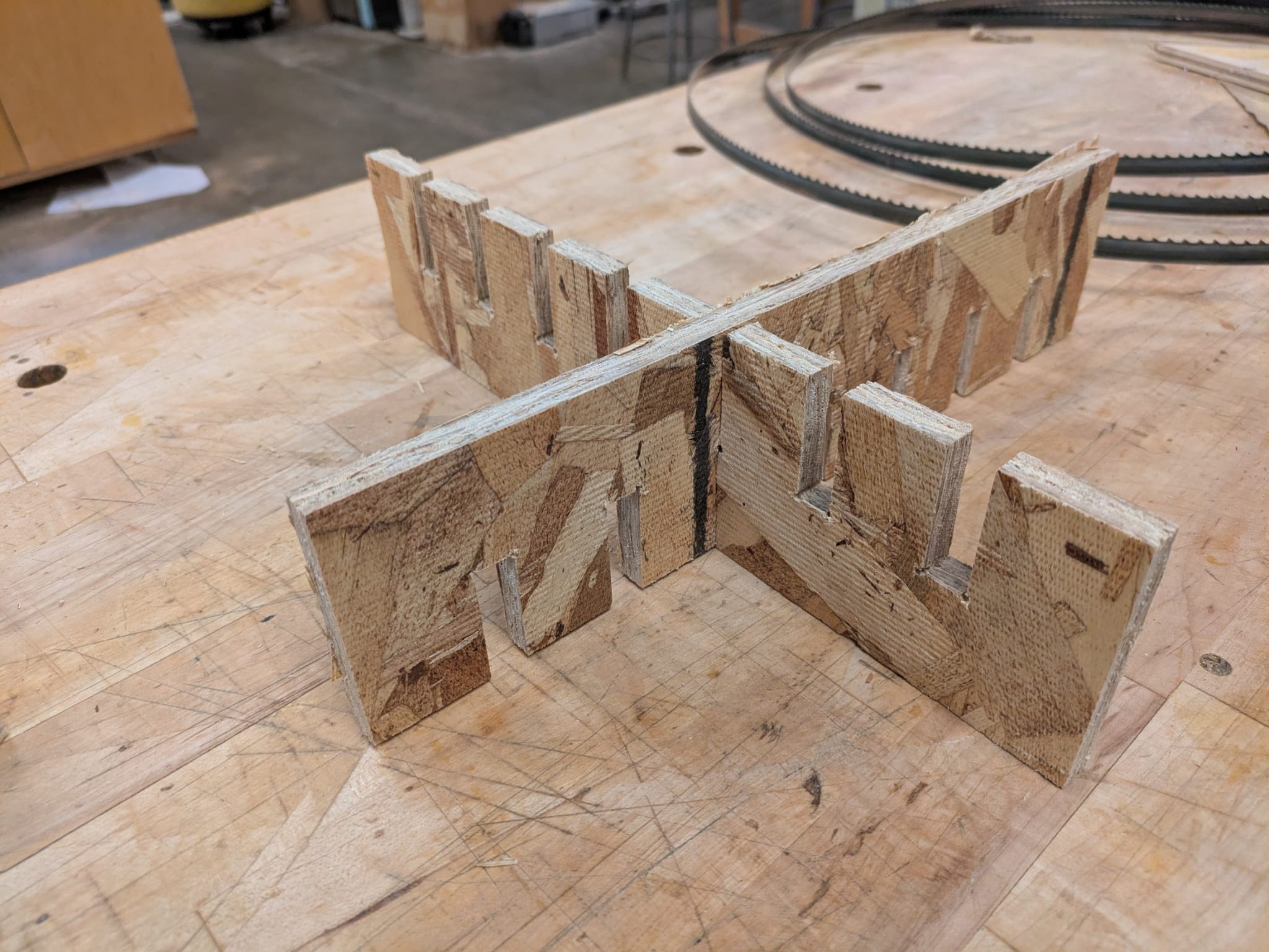
Above are the two tests of an H and J configuration. I wanted to have the ability to swap out the side walls to test the differences between the two. I was using Finger Tenons from this guide that Alfonso shared with us.
Working with Scrap Material
At my buddy Max's shop, we had limited material. I liked that constraint. Looking through a pile of speaker drivers saved from trash, I picked two small ones that were in ok shape and seem to be able to handle mid frequency. In terms of plywood, I had limited choices. I hate MDF and I wanted to make them out of plywood, and I found 5.75" wide scrap. I'd have to change my initial idea to match with what i had on hand.
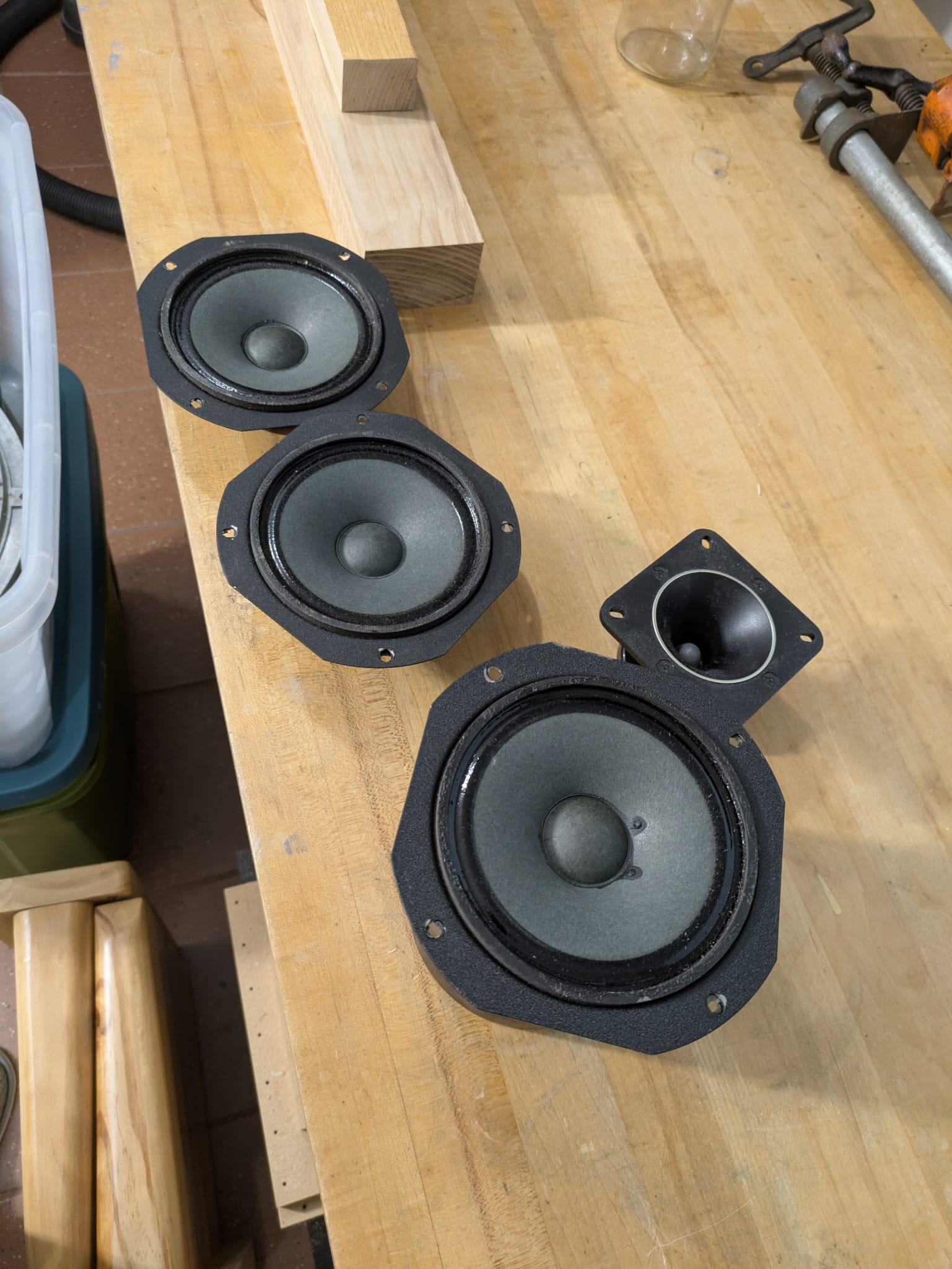
Speakers saved from the trash.
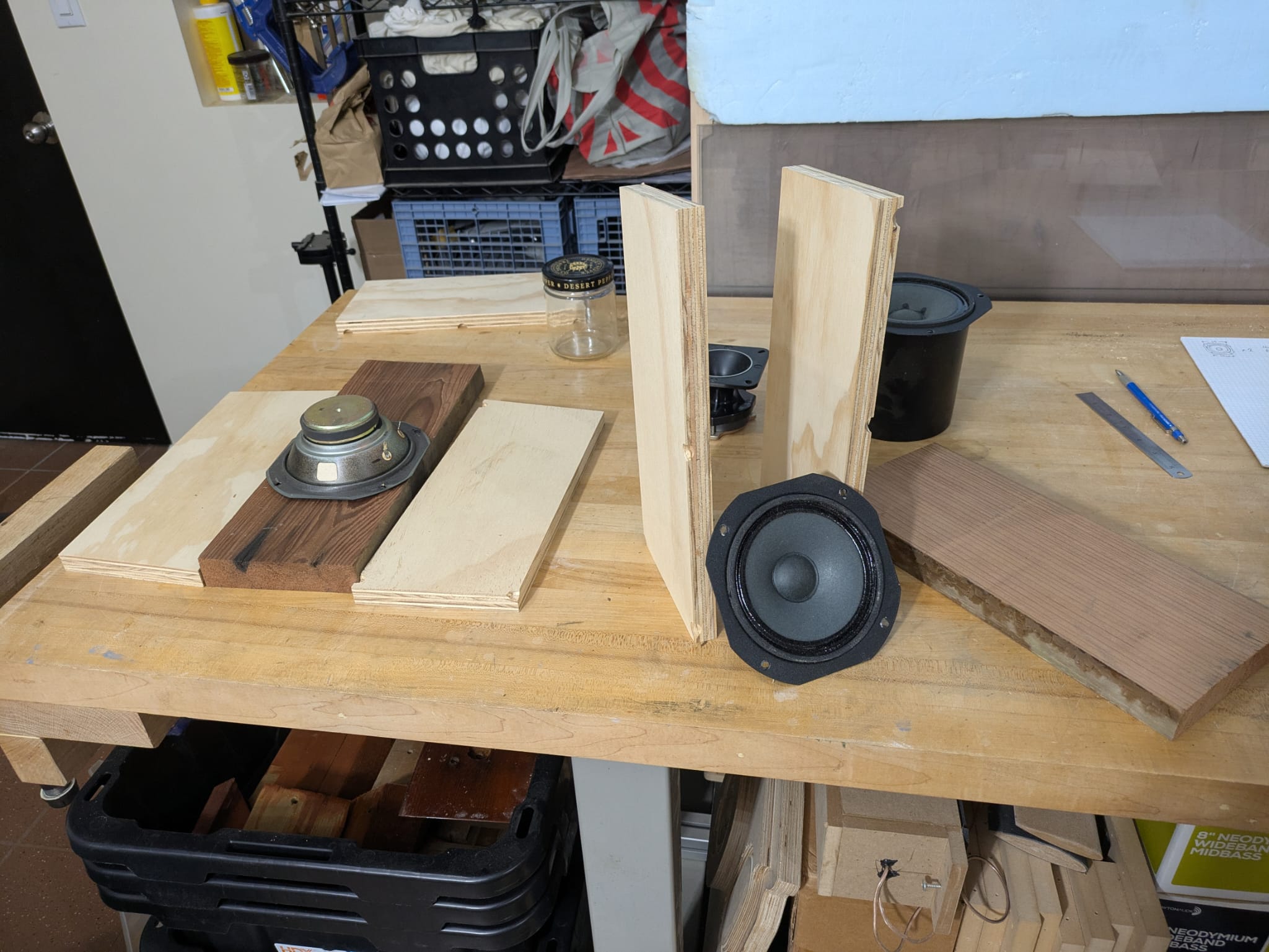
Above is the assorted plywood for the cabinet and two drivers.
I was running an inventory of what I could scrounge. Scrappy but no waste!
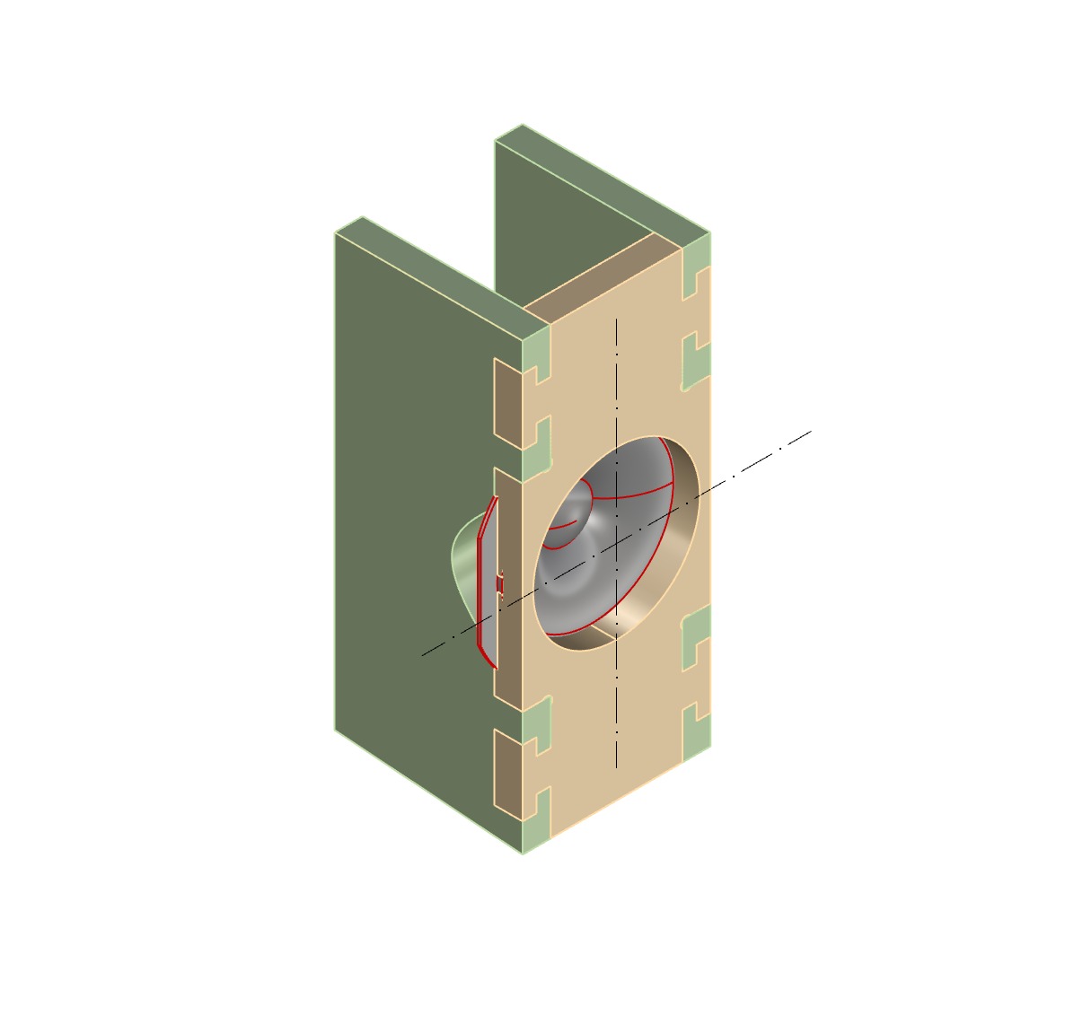
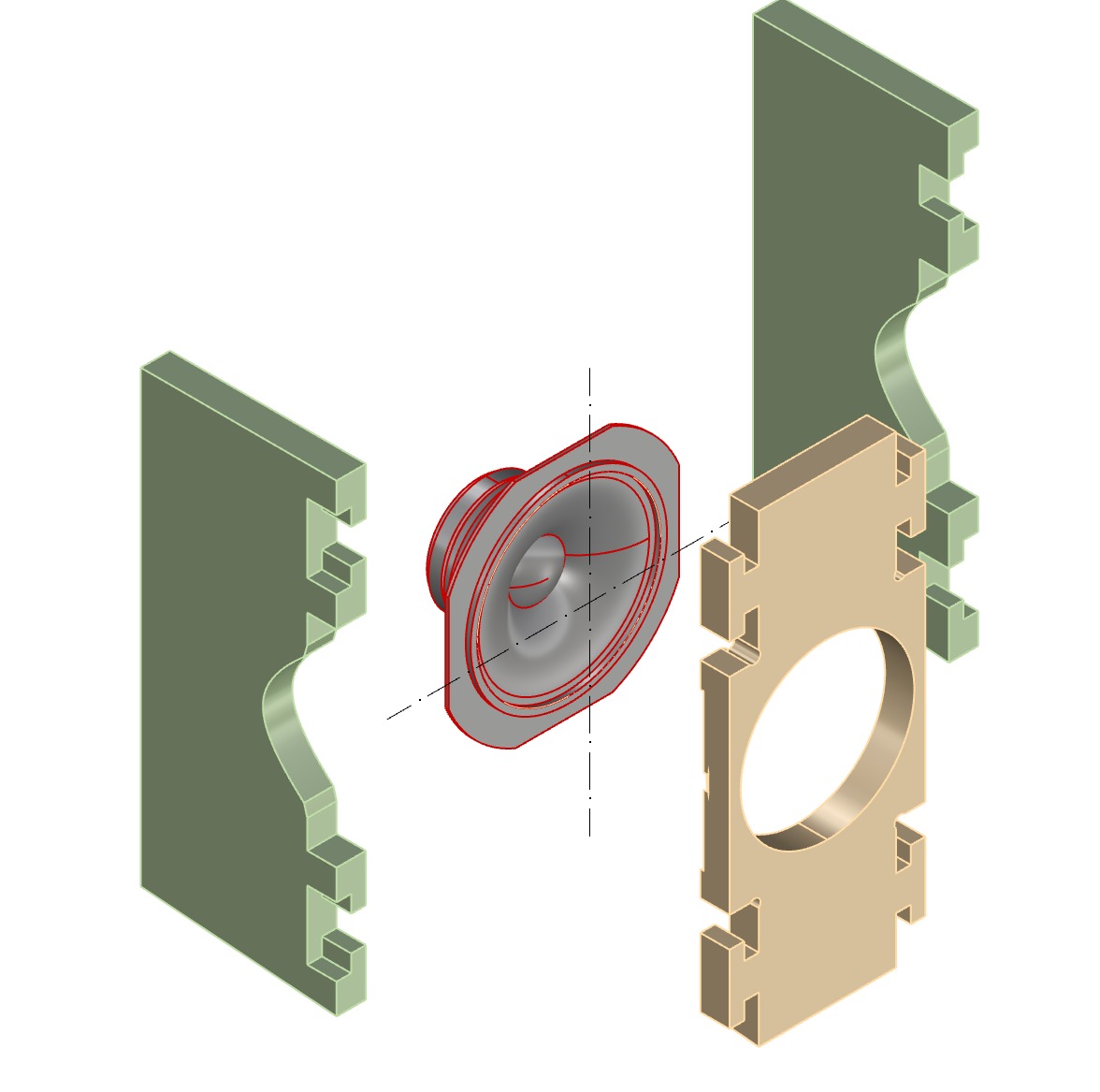
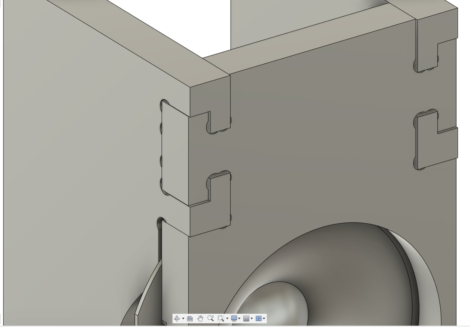
Diagram for speaker assembly.
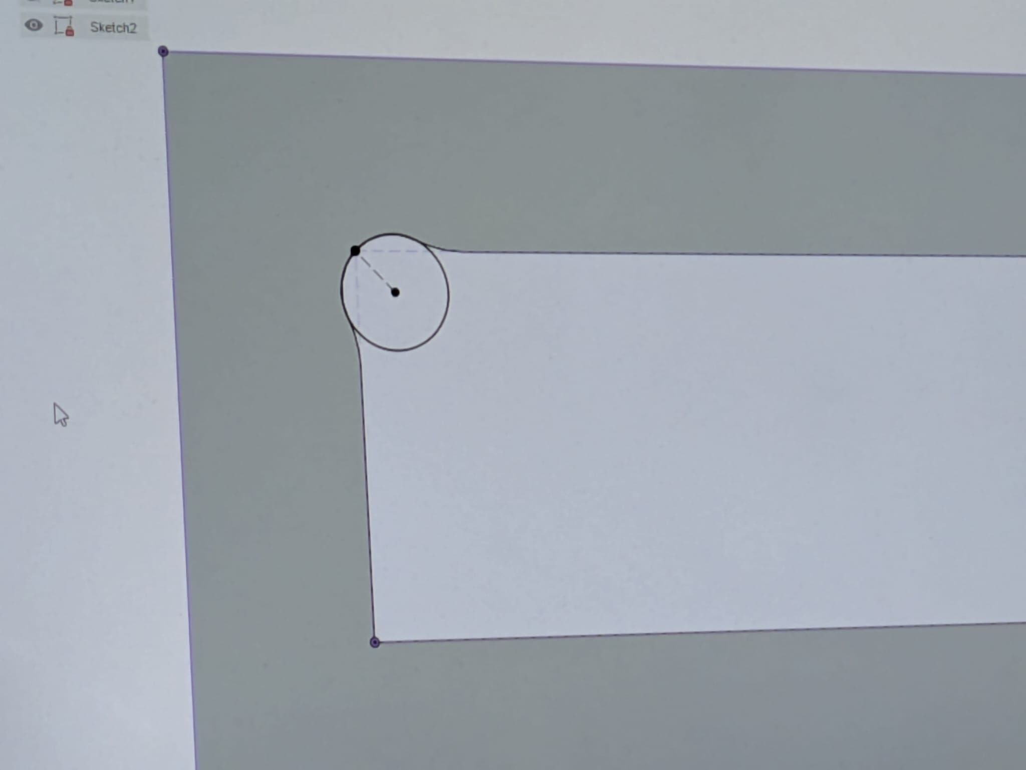
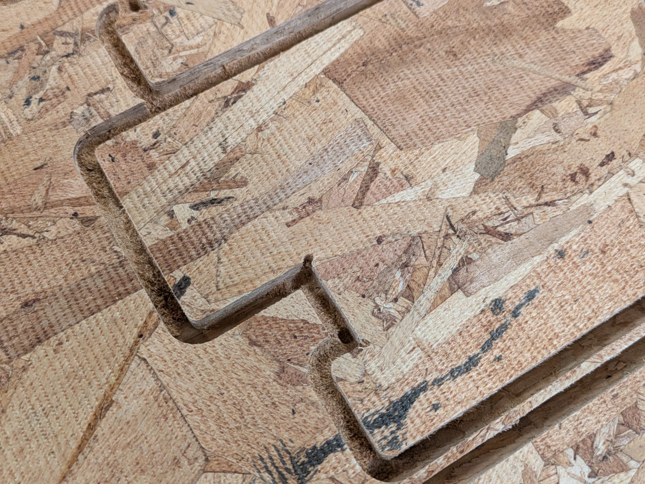
I really like these joints for slotted connections as an alternative to the "mickey-mouse ears" tab drill hole. I think they're somehow more elegant.
Modeled the joint conditions in Fusion with constrained parameters.
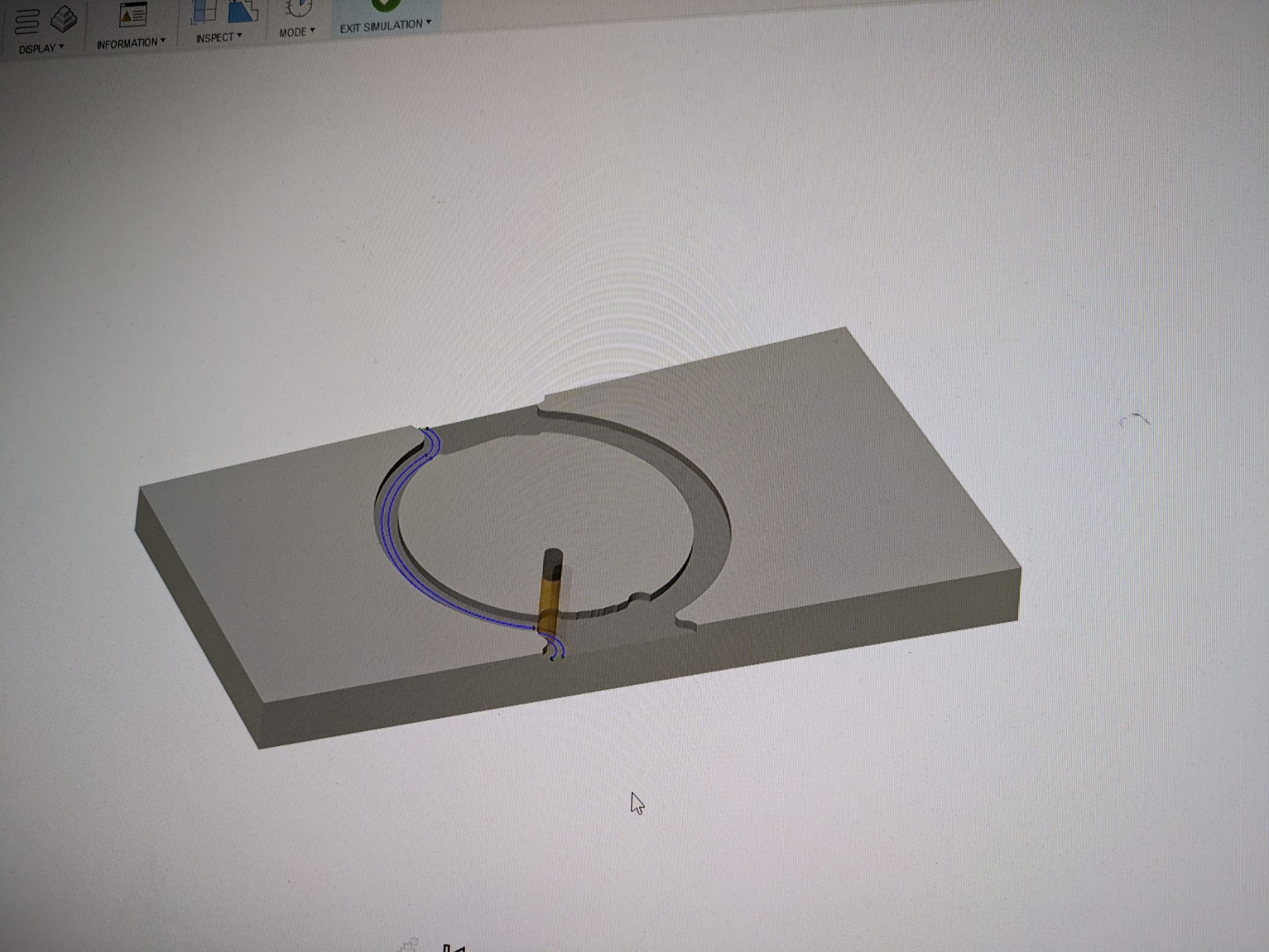
Simulated milling pass with the .25" cheap-o alibaba generic end mill.
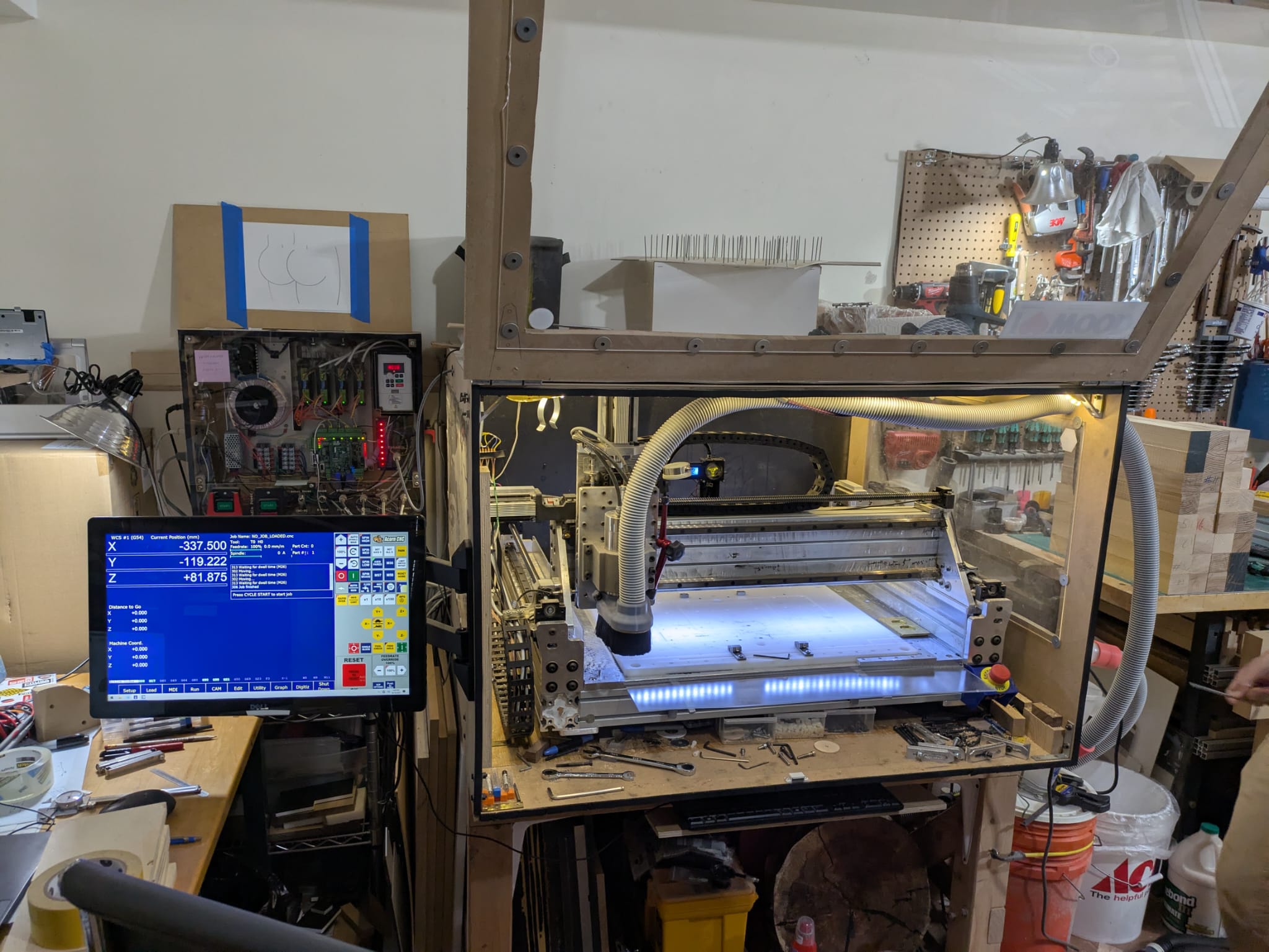
Somewhere in a basement deep in Brooklyn lives a slap-dash DIY mill.
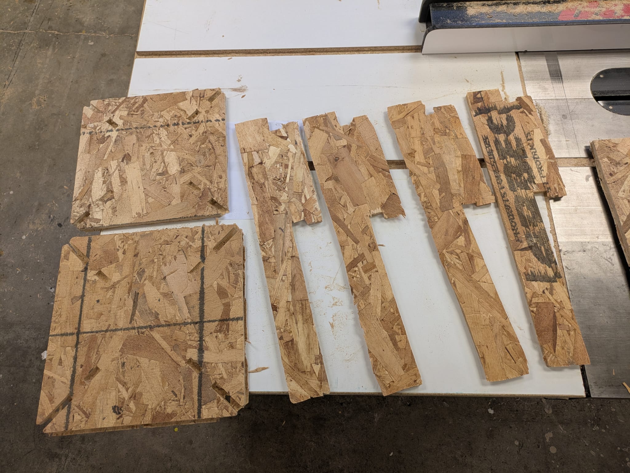
Time lapse of milling job of one baffle face.
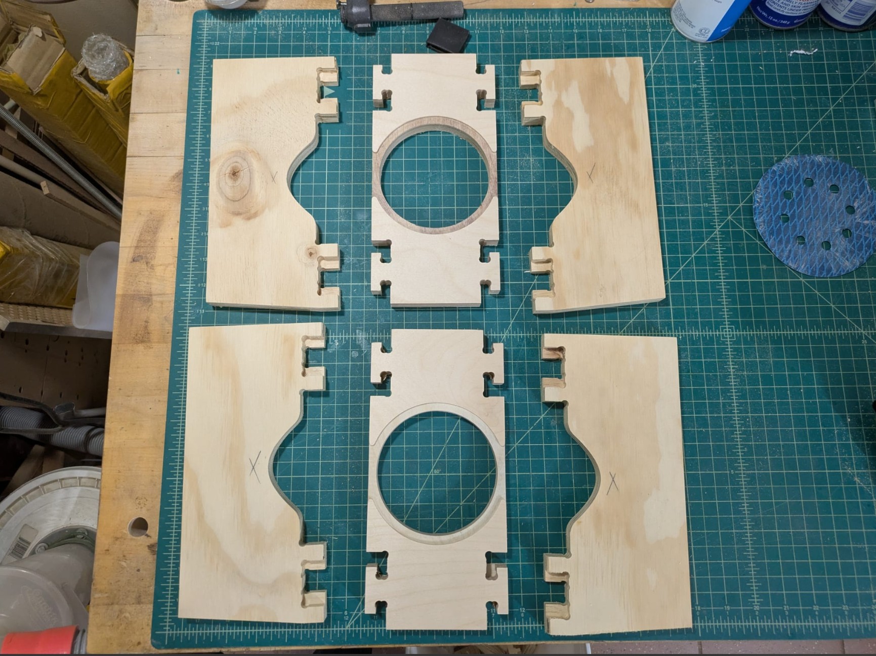
Milled stock. Finishing involved a light sanding to get rid of residual onion layers.
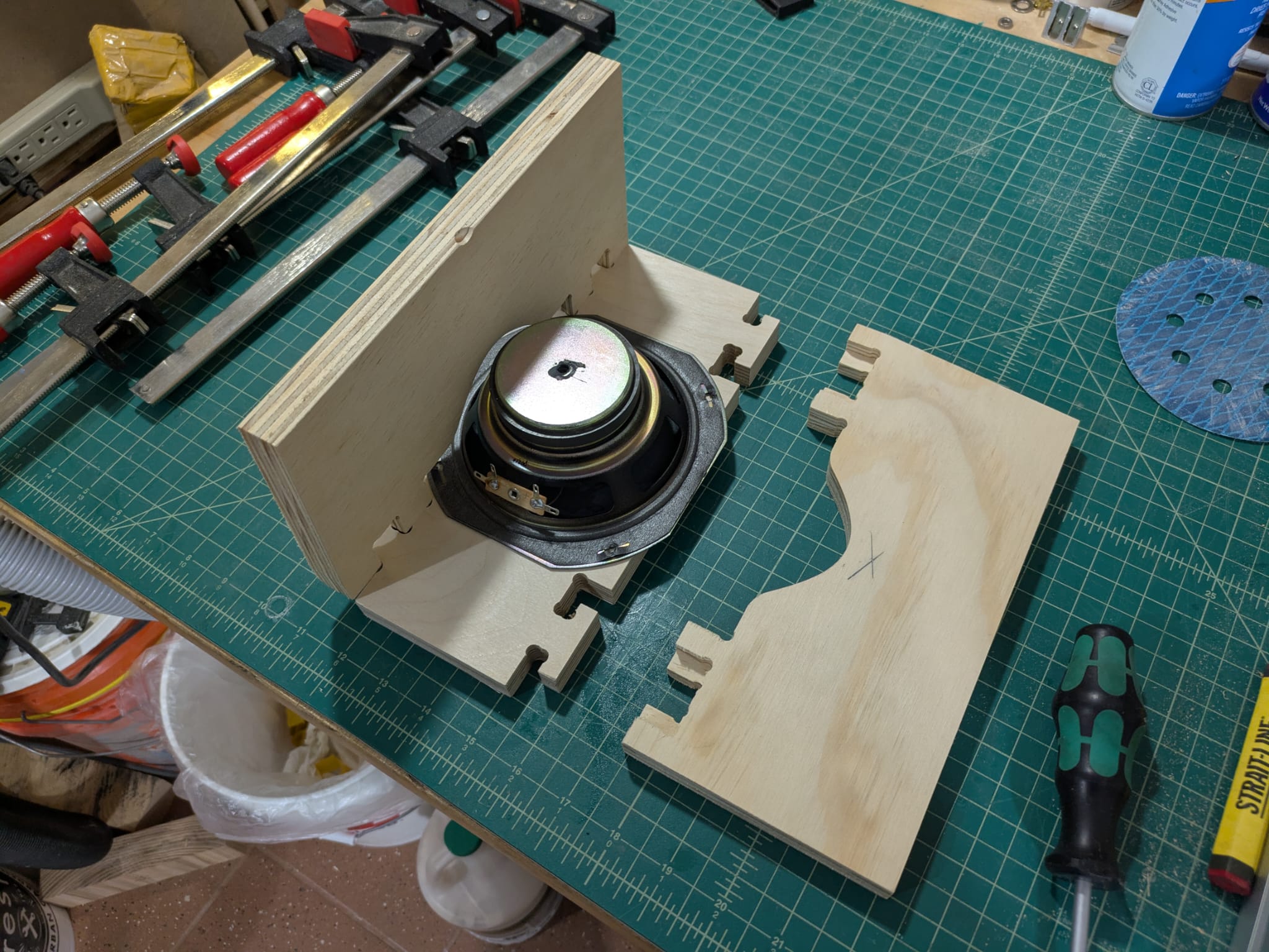
Assembly of 1 of 2 speakers.
.02 mm offsets were not generous enough. The pieces pressure fit together but it was really tight and I had to hammer pieces in.
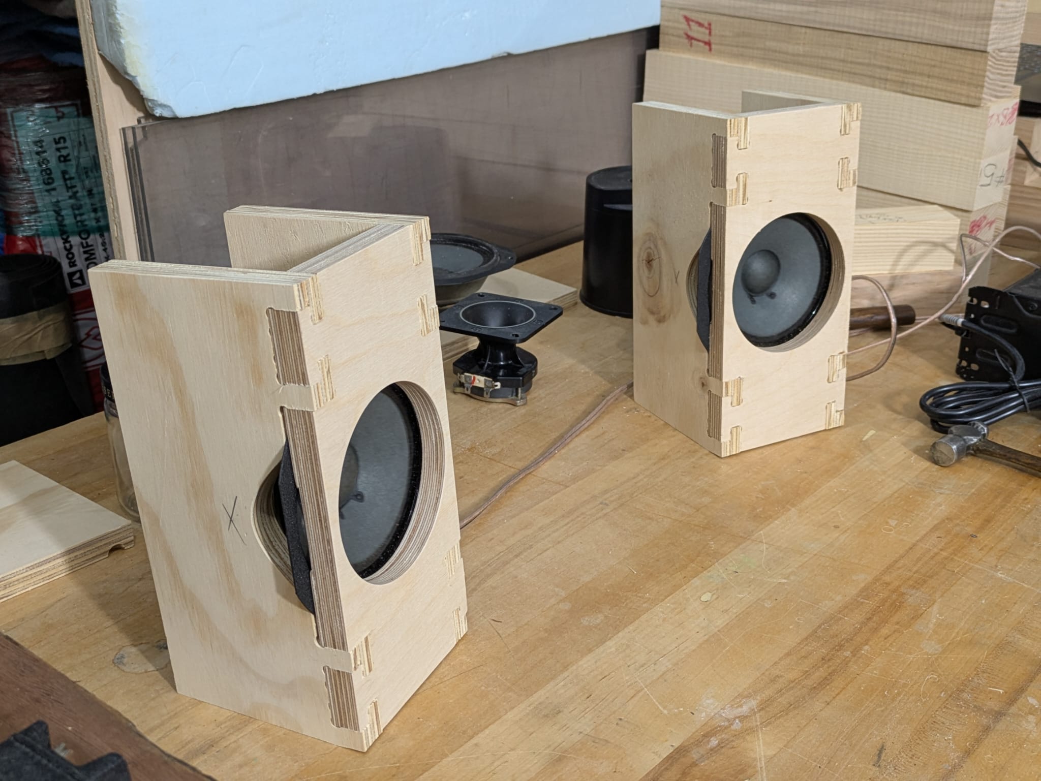
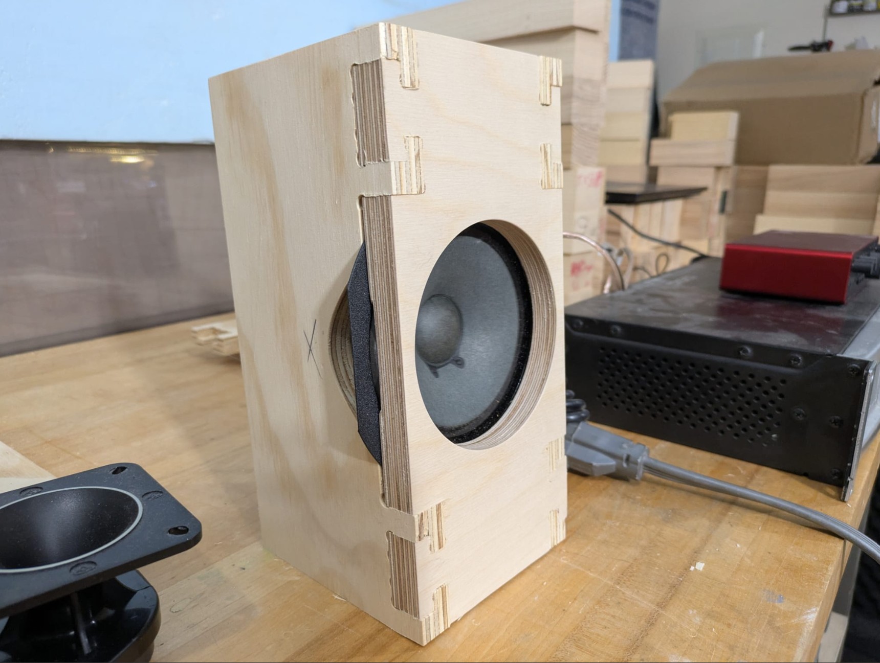
Speakers Complete!
Speaker Testing
I got it working by wiring it to an amplifier I had here. Not bad for 4 hours of planning to execution. I tested the speaker and learned that open-baffle designs demand a large baffle to make the dipole behavior work sensibly at low frequencies. If the baffle is small compared to the wavelength of the sound at a given frequency, the rear wave wraps around and interferes destructively with the front wave, so you lose output and it sounds thin below a certain frequency. In practice that means an open-baffle needs dimensions on the order of the acoustic wavelength (or at least a substantial fraction of it) for the low frequencies you care about; otherwise you either accept the low-frequency roll-off or compensate with EQ, multiple drivers, folded baffles, or horn/porting strategies. Physically, wavelength λ = c / f (where c ≈ 343 m/s is the speed of sound). So the baffle must be sized with the target low-frequency band in mind—small baffles push the dipole roll-off up into the midrange, while very large baffles are needed to preserve bass. I mean also my driver was probably designed for a very limited range.
Final Takeaways
- Leave time! Milling took at least 3x longer than I thought it should.
- Yes, miling is an art, but I feel like managing time this week was the real piece de resistance.
- Open-baffle speakers demand large baffles to work effectively at low frequencies. If the panel is smaller than the wavelength of the sound at a given frequency, the front and rear waves cancel out—causing bass loss.
- Structural rigidity matters. Even slight vibrations or flexing in the baffle or frame can color the sound. Always consider the acoustic wavelength when designing.
- Collaboration made this project possible: huge thanks to Max for lending his speaker-building expertise and CNC, Geoffrey for being flexible and patient during the build, Alfonso for his detailed walkthroughs, and Jenn for running the shops so well!