Final Project - Carnatic Music Pitch Perfection Helper
Gratitude tracker for help on final project: Anthony, Gert, Adin, Alex, Carlotta, Cyrus, Jen, Shah, Jake
Some context on my project
My background in classical music
Much like any other good South Indian, I've been training in Carnatic (South Indian classical) vocals since I was 5-6 years old. Over 2 decades with many gaps and multiple teachers, lots of distractions and interruptions, I'm finally at a point in my training where I could be considered "intermediate". My teacher therefore is currently teaching me how to improvise. Similar to jazz, this is when you're given an allowable permutation of notes (a "raga" in Carnatic music - more context below), and you can play around with them in any order to create new melodies, patterns, and riffs. This is in contrast to existing, structured songs that were composed within that raga already, though you can pick up some note patterns from existing compositions as inspiration.
Some definitions & context on Carnatic music
Things to know to understand this project:
Indian classical music has 2 prominent styles: Carnatic (from the South) and Hindustani (from the North). I'm trained in the former, but the same basic principles apply in both.
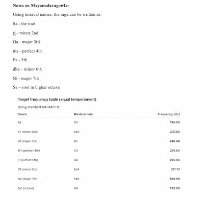
Our music also uses the 12 unique notes of Western music, A through G with sharp or flat variations. However, they are called different things in Indian classical music (the notes are Sa, Ri, Ga, Ma, Pa, Dha, Ni -- analog of Do Re Mi Fa So La Ti). More importantly, the notes are important, but equally critical is the infinite space between the notes, i.e., microtones.
Carnatic music is organized into 72 fundamental "ragas" (and infinite derivative ones). A raga is a framework. It is basically a permutation of notes and rules for creating unique melodies. While it is fundamentally a scale, Indian classical music also assigns very specific moods, personalities, phrases, ornaments, emotions etc. to each raga.
Finally, as mentioned above, "alapanam" is a slow improvisation done by a musician within a specific raga. In other words, they pick the raga they want to improvise in, and then use only the notes of that scale/raga to compose melodies on the fly. In doing so, they have to convey the emotion of that raga. It's often used as an introduction to get an audience situated in the mood of the raga, before the performer starts to perform actual compositions within it.
For the purpose of this assignment: a raga is a permuation of notes. My teacher is teaching me to do alapanam within a raga called Maya Malavagowla, which is the most fundamental and very first raga that any new student learns in Carnatic music.
Describing the process
1. Concept, Motivation & System Overview
Part of the impetus for this is that one of the hardest things for beginners isn’t rhythm or lyrics — it’s pitch. Unlike Western music, we don’t tune to a piano or fixed notes. We learn pitch by ear, guided by a teacher — and that feedback is slow, subjective, and often intimidating.
So I wanted to ask: what if pitch feedback could be immediate, intuitive, and embodied — not judgmental? So this is a real-time pitch feedback box designed specifically for Mayamalavagowla, the first raga everyone learns. It listens to your voice, figures out what note you’re singing, and gives you instant feedback using light and sound.
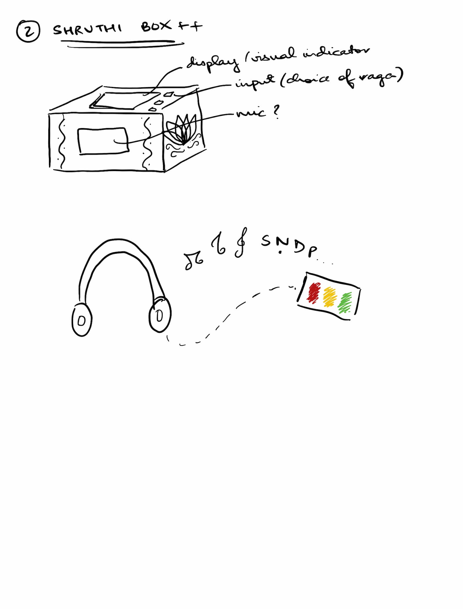
Here's the initial idea and system diagram (doesn't include the casing but want it to look like a shruthi box, a device we use in Carnatic that plays a resonant tanpura (stringed instrument) note set to keep you on pitch with your base note (mine is G)):
2. Overall System Architecture
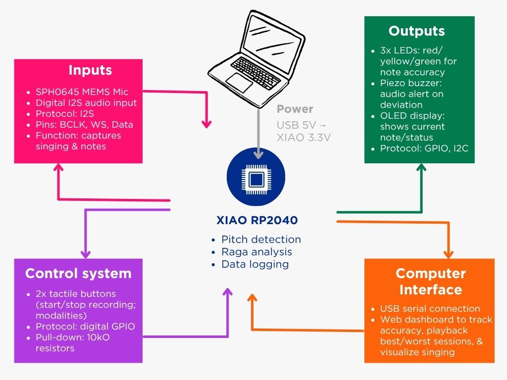
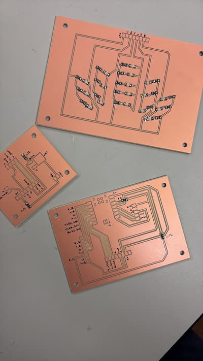
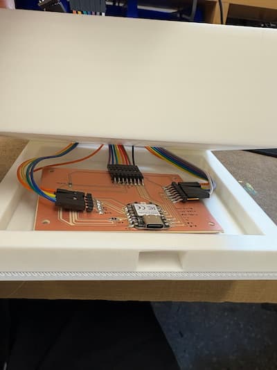
The box uses 3 PCBs:
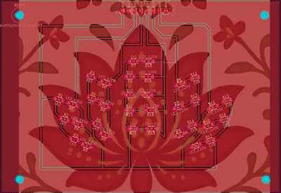
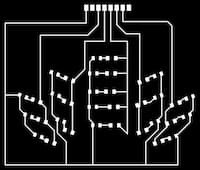
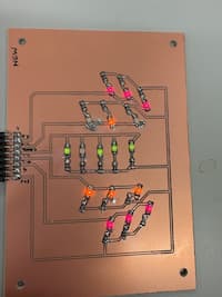
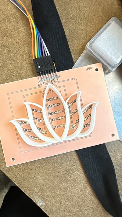
an LED board with 17 LEDs of 3 colors arranged symmetrically in 5 petals of a flower (red – 3 on the left and 3 on the right, yellow - 3 on the left and 3 on the right, green – 5 arranged in the middle petal)
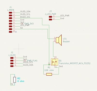
a “lid” board that sits within the lid of the box, which contains a connector to the main board, an OLED .96” display, a speaker/buzzer, a MOSFET transistor, a 10K ohm resistor, and a two-pin header for the option of adding a switch
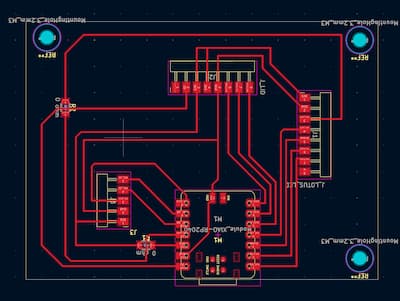
a main board with a USB-powered XIAO RP2040 microcontroller and connectors to each of the above 2 boards, plus connectors to an Adafruit I2S mic breakout board which serves as input
Thus the input comes from the mic, and the outputs are 17 LEDs, 1 mic/buzzer, and 1 OLED.
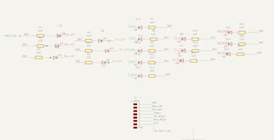
There was a time when I wanted to put everything on one PCB, and made a schematic to design this -- but that was just messy and would involve far too complex wiring. I thought this lent itself nicely to positioning in different parts of the box.
This was my overall desired functioning:
[Input] Mic will detect when singing is happening using an amplitude/energy threshold (rMS), only run pitch detection when voice is detected, and ignore frames when the amplitude is low. Then it’ll run an FFT
This raga has 7 notes, i.e., 8 frequencies you are allowed to sing (2 are the same note in different octaves). I've mapped them below:
[Output] LEDs:
If the singer is singing the right note (+/- 70 (placeholder) cents), the green LEDs stay lit up
If they are singing completely incorrect notes (outside 70 cents), the red LEDs stay lit up
If they are approaching / at risk of incorrect notes (on an allowed note but +/- 30-70 cents), the yellow LEDs flash
A few other notes: to reduce overstimulation, instead of switching color instantly, require the new state to “win” for a short time: Compute note classification every frame (e.g., 20–50 ms), Keep a “candidate state, Only commit to it if it stays consistent for 150–250 ms, Once you commit, hold the display for 200–400 ms before allowing another change. Also, Confidence gate: Only update LEDs when amplitude (RMS) is above a threshold (voice present), and pitch confidence is above a threshold (or the algorithm returns “valid pitch”). Finally, make red rare, only use it during sustained wrong (during fast singing, avoid red unless they land clearly “wrong” for >200ms)
[Output] Buzzer: stays quiet as long as the singer is right; makes a beep sound if the singer is singing completely incorrect notes (same criteria as red LEDs). Only buzz if it’s been “red” continuously for e.g. 200–300 ms and limit buzzing to e.g. once every 500 ms max
[OPTIONAL] [Output] OLED:
When connected to power, displays “Welcome! Ready to start practicing?”
When audio is detected, displays “Audio detected”
When audio stops, says “Audio stopped”
[HIGHLY OPTIONAL] Can either also display the waveform or the frequency value of each note (or perhaps the note that value range is mapped to), or the number of times the red, green, and yellow lights lit up (or number of times the buzzer rang)
DO THIS LAST, IF TIME PERMITS
3. Electronics Design: Custom PCBs
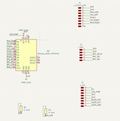
I designed all of these in Kicad and ran them by Anthony and/or Quentin. There were the usual fun challenges of traces without using 0 ohm resistors - in the end I had to do it in a few places
3.1 Main Board (Microcontroller & Input)
3.2 LED Board (Visual Output)
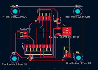
3.3 Lid Board (Buzzer & Optional OLED)
All files can be found in the download section.
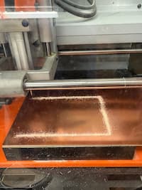
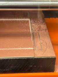
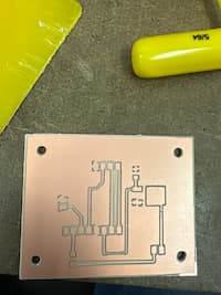
4. PCB Fabrication & Assembly
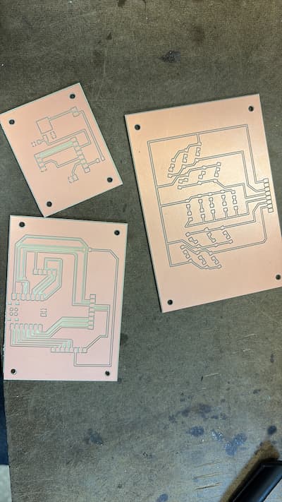
This I think was the most traumatic day of the whole project. I faced not one, not two, but SIX failed attempts at milling my PCBs the way I wanted them - either because the copper was warped, or the tape was insufficient, or the endmills weren't actually as sharp as they looked, or the Roland milling machine just didn't want to. I have a distinct memory of Adin, Carlotta and I doing breathing exercises at 1am, and Adin and I marching to EECS lab to ask for Anthony's help + some spare flat copper.
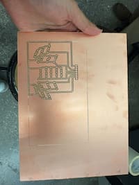
Eventually, here's what they looked like, crisp and clean. I think I could run the Roland in my sleep now.
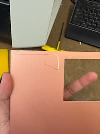
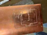
BUT here are my various, joyful failures:
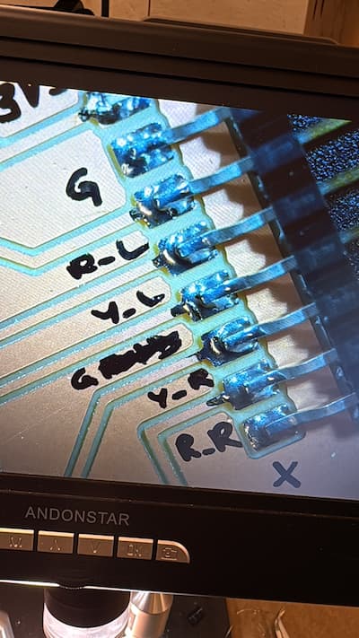
Then I moved on to soldering. Famously my long-term enemy (just didn't think I had the dexterity for it before), but in good news, I've come round and think I've gotten better at it!
Unfortunately I made one big mistake, which is that I soldered all LEDs in the incorrect orientation/wrong polarity. I discuss this more in Week 9: Output Devices. Some learnings: lead-free solder is worse than lead-with(?); don't solder at 1am when you're frustrated from failures; and it's not the end of the world if you get a bit of solder on your board - just as long as it's not bridging anything.
5. Electronics Testing & Bring-Up
5.1 LED Testing
Test code
// ===== LED pin definitions =====
#define RED_RIGHT  0   // D0
#define YEL_RIGHT  1   // D1
#define GREEN_LED  2   // D2
#define YEL_LEFT   3   // D3
#define RED_LEFT   10  // D10

int leds[] = {
  RED_RIGHT,
  YEL_RIGHT,
  GREEN_LED,
  YEL_LEFT,
  RED_LEFT
};

void setup() {
  Serial.begin(115200);
  delay(1000);
  Serial.println("Starting LED hardware test");

  // Set LED pins as outputs
  for (int i = 0; i < 5; i++) {
    pinMode(leds[i], OUTPUT);
    digitalWrite(leds[i], HIGH); // OFF (active-low)
  }
}

void loop() {
  // Step through each LED group
  for (int i = 0; i < 5; i++) {
    Serial.print("Turning ON LED group on pin D");
    Serial.println(leds[i]);

    digitalWrite(leds[i], LOW);   // ON
    delay(800);

    digitalWrite(leds[i], HIGH);  // OFF
    delay(300);
  }

  // All on
  Serial.println("ALL LEDs ON");
  for (int i = 0; i < 5; i++) {
    digitalWrite(leds[i], LOW);
  }
  delay(1500);

  // All off
  Serial.println("ALL LEDs OFF");
  for (int i = 0; i < 5; i++) {
    digitalWrite(leds[i], HIGH);
  }
  delay(1500);
}
LEDs working
5.2 Buzzer Testing
(This was a simple line of code that worked with my eventual longer code - didn't need to test much)
5.3 Microphone & Input Testing
This was trickier. I was using an Adafruit breakout board, and my sample code I originally was using didn't work:
        #include

#define PIN_I2S_BCLK  6   // <-- change to your actual XIAO pin numbers
#define PIN_I2S_WS    7
#define PIN_I2S_DATA  8

I2S i2s;

void setup() {
  Serial.begin(115200);
  delay(1000);
  Serial.println("Starting I2S mic test...");

  // Some I2S libs call WS "LRCLK"
  i2s.setBCLK(PIN_I2S_BCLK);
  i2s.setDATA(PIN_I2S_DATA);
  i2s.setLRCLK(PIN_I2S_WS);

  // If your core supports this signature:
  if (!i2s.begin(16000)) {   // 16 kHz
    Serial.println("ERROR: i2s.begin failed");
    while (1) delay(10);
  }

  Serial.println("Mic initialized OK. Open Serial Plotter (115200).");
}

void loop() {
  if (i2s.available()) {
    int32_t s = i2s.read();
    Serial.println(abs((int)(s >> 8)));  // quick magnitude for plotting
  }
}
So we used Arduino's inbuilt examples for an Adafruit mic, with some slight amendments with Anthony's help:
/*
   I2S stereo microphone (input) example
   Run using the Arduino Serial Plotter to see waveform.
   Released to the Public Domain by Earle F. Philhower, III

   For the Google AIY Voice Hat Microphone daughterboard, part
   of the Raspberry Pi AIY cardboard box, the I2S stereo pinout
   looking at the board top with the RPI logo on the left hand
   side:
            +--   ------------------------------------  --+
   left RPI | (1) GND (2) DIN (3) BCLK (4) LRCLK (5) 3.3V | AIY right
       logo +---------------------------------------------+ logo

   For an Adfruit I2S MEMS microphone (https://www.adafruit.com/product/3421),
   connect the pins as follows:

      DOUT -> GPIO0
      BCLK <- GPIO1
      LRCL <- GPIO2  # LRCLK = BCLK + 1
      GND <-> GND
      3V  <-> 3V3OUT

   The other idiosyncrasy of most modern MEMS microphones is that they
   require a minimum clock rate to wake up. For example, the SPH0645
   microphone needs at least 1MHz.
*/

#include

I2S i2s(INPUT);

void setup() {
  Serial.begin(115200);

  i2s.setDATA(D9);
  i2s.setBCLK(D7); // Note: LRCLK = BCLK + 1
  // i2s.setBitsPerSample(16);
  // i2s.setFrequency(22050);
  // NOTE: The following values are known to work with the Adafruit microphone:
  i2s.setBitsPerSample(32);
  i2s.setFrequency(8000);
  i2s.begin();

  while (1) {
    int16_t l, r;
    i2s.read16(&l, &r);
    // NOTE: Adafruit microphone word size needs to match the BPS above.
    // int32_t l, r;
    // i2s.read32(&l, &r);
    if(l!=0){
    Serial.printf("%d\r\n",  l);
    }
  }
}

void loop() {
  /* Nothing here */
}
Final code I used for the whole system. I have zero coding experience, so was heavily helped by Anthony and Claude AI here.
/*
   Carnatic Pitch Detector - Mayamalavagowla Raga
   Uses FFT for real-time pitch detection
   Base pitch: G3 (196 Hz)
*/

#include
#include

// ========== FFT CONFIGURATION ==========
#define SAMPLES 512          // Power of 2, larger = better frequency resolution
#define SAMPLING_FREQ 8000   // Match your I2S frequency
#define AMPLITUDE_THRESHOLD 200  // Minimum volume to detect singing (tune this!)

// FFT objects
double vReal[SAMPLES];
double vImag[SAMPLES];
ArduinoFFT FFT = ArduinoFFT(vReal, vImag, SAMPLES, SAMPLING_FREQ);

// I2S microphone
I2S i2s(INPUT);

// ========== MAYAMALAVAGOWLA FREQUENCIES (G3 base) ==========
const float allowedFreqs[] = {
  196.00,  // Sa  (G3)
  207.65,  // R1  (Ab3)
  246.94,  // G1  (B3)
  261.63,  // M1  (C4)
  293.66,  // P   (D4)
  311.13,  // D1  (Eb4)
  369.99,  // N2  (F#4)
  392.00   // Sa' (G4)
};

const char* noteNames[] = {"Sa", "R1", "G1", "M1", "P", "D1", "N2", "Sa'"};
const int numNotes = 8;

// ========== CENTS TOLERANCE ==========
// Cents = 1200 * log2(freq1/freq2)
// 70 cents ≈ 4.1% frequency difference
const float CENTS_PERFECT = 50.0;   // More forgiving
const float CENTS_WARNING = 100.0;
// Beyond 70 cents = red (wrong)

// ========== LED PIN DEFINITIONS ==========
/// ========== LED PIN DEFINITIONS ==========
// Each color group has just ONE pin (no arrays needed!)
const int LED_GREEN = D2;           // Controls all 5 green LEDs
const int LED_YELLOW_LEFT = D3;     // Controls all 3 yellow left LEDs
const int LED_YELLOW_RIGHT = D1;    // Controls all 3 yellow right LEDs
const int LED_RED_LEFT = D10;       // Controls all 3 red left LEDs
const int LED_RED_RIGHT = D0;       // Controls all 3 red right LEDs

// ========== BUZZER PIN ==========
const int BUZZER_PIN = D6;          // Add your buzzer pin here (check your schematic!)

// ========== STATE TRACKING ==========
enum NoteState {
  STATE_CORRECT,    // Green - within 30 cents
  STATE_WARNING,    // Yellow - 30-70 cents off
  STATE_WRONG       // Red - more than 70 cents off
};

NoteState currentState = STATE_CORRECT;
NoteState candidateState = STATE_CORRECT;
unsigned long candidateStartTime = 0;
unsigned long lastStateChangeTime = 0;

const unsigned long CONFIRMATION_TIME = 200;  // ms to confirm new state
const unsigned long HOLD_TIME = 300;          // ms to hold display

// ========== FUNCTION DECLARATIONS ==========
double calculateRMS();
NoteState classifyPitch(double frequency, int &closestNote, float ¢sOff);
void updateLEDs(NoteState state);
const char* stateToString(NoteState state);

// ========== SETUP ==========
void setup() {
  Serial.begin(115200);
  delay(1000);

  Serial.println("=== Carnatic Pitch Detector ===");
  Serial.println("Initializing I2S microphone...");

  // Setup I2S microphone
  i2s.setDATA(D9);
  i2s.setBCLK(D7);
  i2s.setBitsPerSample(32);
  i2s.setFrequency(8000);
  i2s.begin();

  // Initialize LED pins
  pinMode(LED_GREEN, OUTPUT);
  pinMode(LED_YELLOW_LEFT, OUTPUT);
  pinMode(LED_YELLOW_RIGHT, OUTPUT);
  pinMode(LED_RED_LEFT, OUTPUT);
  pinMode(LED_RED_RIGHT, OUTPUT);

  // Initialize buzzer pin
  pinMode(BUZZER_PIN, OUTPUT);
  digitalWrite(BUZZER_PIN, LOW);  // Make sure buzzer is off initially


  // Turn ALL LEDs OFF initially (HIGH = off for active-low)
  digitalWrite(LED_GREEN, HIGH);
  digitalWrite(LED_YELLOW_LEFT, HIGH);
  digitalWrite(LED_YELLOW_RIGHT, HIGH);
  digitalWrite(LED_RED_LEFT, HIGH);
  digitalWrite(LED_RED_RIGHT, HIGH);

  Serial.println("All LEDs should be OFF now");
  delay(500);

  Serial.println("Ready! Start singing...");
  Serial.println("Format: Frequency | Note | Cents Off | State");
  Serial.println("-----------------------------------------------");
}

// ========== MAIN LOOP ==========
void loop() {
  // Step 1: Collect audio samples
  for(int i = 0; i < SAMPLES;) {
    int16_t l, r;
    l=1;
    i2s.read16(&l, &r);
    //Serial.println(l);
    // Use left channel, scale down from 32-bit
    if(l!=0){
    vReal[i] = (double)(l);  // Convert to ~16-bit range
    vImag[i] = 0.0;
    i++;
    }
    //Serial.println(l);
  }

  // Step 2: Check if there's enough volume (is someone singing?)
double rms = calculateRMS();

// DEBUG: Always print RMS value so we can see what's happening
Serial.print("RMS: ");
Serial.print(rms);
Serial.print(" | ");

if(rms < AMPLITUDE_THRESHOLD) {
  // No singing detected - turn ALL LEDs OFF (write HIGH)
  digitalWrite(LED_GREEN, HIGH);
  digitalWrite(LED_YELLOW_LEFT, HIGH);
  digitalWrite(LED_YELLOW_RIGHT, HIGH);
  digitalWrite(LED_RED_LEFT, HIGH);
  digitalWrite(LED_RED_RIGHT, HIGH);
  Serial.println("Silence... (all LEDs OFF)");
  delay(50);
  return;
}

  // Step 3: Run FFT (syntax for arduinoFFT v2.x)
  FFT.windowing(FFTWindow::Hamming, FFTDirection::Forward);
  FFT.compute(FFTDirection::Forward);
  FFT.complexToMagnitude();

  // Step 4: Find dominant frequency - IMPROVED VERSION
double peakFreq = FFT.majorPeak();
double peakMagnitude = 0;

// Find the magnitude of the peak frequency
// This helps us filter out weak/noisy frequencies
for(int i = 0; i < SAMPLES/2; i++) {
  double freq = (i * 1.0 * SAMPLING_FREQ) / SAMPLES;
  if(abs(freq - peakFreq) < 5) {  // Within 5 Hz of peak
    if(vReal[i] > peakMagnitude) {
      peakMagnitude = vReal[i];
    }
  }
}

// Only process if the peak is strong enough
if(peakMagnitude < 1000) {
  Serial.println("Signal too weak, ignoring... (all LEDs OFF)");
  // Turn all LEDs OFF (write HIGH)
  digitalWrite(LED_GREEN, HIGH);
  digitalWrite(LED_YELLOW_LEFT, HIGH);
  digitalWrite(LED_YELLOW_RIGHT, HIGH);
  digitalWrite(LED_RED_LEFT, HIGH);
  digitalWrite(LED_RED_RIGHT, HIGH);
  delay(50);
  return;
}

  // Step 5: Classify the note
  int closestNote = -1;
  float centsOff = 0.0;
  NoteState newState = classifyPitch(peakFreq, closestNote, centsOff);

  // Step 6: Debounce state changes
  if(newState != candidateState) {
    // New candidate state
    candidateState = newState;
    candidateStartTime = millis();
  }
  else if(newState != currentState) {
    // Candidate state is stable, check if it's been long enough
    if(millis() - candidateStartTime >= CONFIRMATION_TIME) {
      // Check if we're past the hold time from last change
      if(millis() - lastStateChangeTime >= HOLD_TIME) {
        currentState = newState;
        lastStateChangeTime = millis();
      }
    }
  }

  // Step 7: Update LEDs based on current state
  updateLEDs(currentState);

  // Step 8: Print debug info
Serial.print("Mag: ");
Serial.print(peakMagnitude, 0);
Serial.print(" | ");
Serial.print(peakFreq, 2);
Serial.print(" Hz | ");
// ... rest of your print statements
  Serial.print(peakFreq, 2);
  Serial.print(" Hz | ");
  if(closestNote >= 0) {
    Serial.print(noteNames[closestNote]);
  }
  Serial.print(" | ");
  Serial.print(centsOff, 1);
  Serial.print(" cents | ");
  Serial.println(stateToString(currentState));

  delay(20);  // ~50 Hz update rate
}


// ========== HELPER FUNCTIONS ==========

// Calculate RMS (root mean square) for volume detection
double calculateRMS() {
  double sum = 0;
  for(int i = 0; i < SAMPLES; i++) {
    sum += vReal[i] * vReal[i];
  }
  return sqrt(sum / SAMPLES);
}

// Classify pitch and return state
NoteState classifyPitch(double frequency, int &closestNote, float ¢sOff) {
  // Find the closest allowed note
  float minDiff = 999999;
  closestNote = 0;

  for(int i = 0; i < numNotes; i++) {
    float diff = abs(frequency - allowedFreqs[i]);
    if(diff < minDiff) {
      minDiff = diff;
      closestNote = i;
    }
  }

  // Calculate cents deviation
  // cents = 1200 * log2(f_detected / f_target)
  float targetFreq = allowedFreqs[closestNote];
  centsOff = 1200.0 * log2(frequency / targetFreq);

  // Classify based on cents
  float absCents = abs(centsOff);

  if(absCents <= CENTS_PERFECT) {
    return STATE_CORRECT;
  }
  else if(absCents <= CENTS_WARNING) {
    return STATE_WARNING;
  }
  else {
    return STATE_WRONG;
  }
}

// Update LED display based on state
void updateLEDs(NoteState state) {
  // Buzzer control variables (static = remembers values between function calls)
  static unsigned long lastBuzzTime = 0;
  static unsigned long redStartTime = 0;

  // FIRST: Turn ALL LEDs OFF (write HIGH for active-low)
  digitalWrite(LED_GREEN, HIGH);
  digitalWrite(LED_YELLOW_LEFT, HIGH);
  digitalWrite(LED_YELLOW_RIGHT, HIGH);
  digitalWrite(LED_RED_LEFT, HIGH);
  digitalWrite(LED_RED_RIGHT, HIGH);

  // THEN: Turn on only the appropriate ones (write LOW to turn ON)
  switch(state) {
    case STATE_CORRECT:
      // Turn on ONLY green LEDs
      digitalWrite(LED_GREEN, LOW);
      Serial.print("🟢 ");
      redStartTime = 0;  // Reset red timer when not in red state
      break;

    case STATE_WARNING:
  // Keep yellow LEDs solid ON (no flashing)
  digitalWrite(LED_YELLOW_LEFT, LOW);   // LOW = ON
  digitalWrite(LED_YELLOW_RIGHT, LOW);  // LOW = ON
  Serial.print("🟡 ");
  redStartTime = 0;
  break;

    case STATE_WRONG:
      // Turn on ONLY red LEDs (both sides)
      digitalWrite(LED_RED_LEFT, LOW);   // LOW = ON
      digitalWrite(LED_RED_RIGHT, LOW);  // LOW = ON
      Serial.print("🔴 ");

      // ===== BUZZER LOGIC =====
      // Start timing when we enter red state
      if(redStartTime == 0) {
        redStartTime = millis();
      }

      // Buzz only if:
      // 1. Been in red state for at least 300ms (sustained wrong note)
      // 2. Haven't buzzed in the last 500ms (rate limiting)
      if((millis() - redStartTime > 300) && (millis() - lastBuzzTime > 500)) {
        tone(BUZZER_PIN, 1000, 100);  // 1000 Hz beep for 100ms
        lastBuzzTime = millis();
        Serial.print(" BUZZ! ");
      }
      break;
  }
}

// Convert state to readable string
const char* stateToString(NoteState state) {
  switch(state) {
    case STATE_CORRECT: return "CORRECT (Green)";
    case STATE_WARNING: return "WARNING (Yellow)";
    case STATE_WRONG: return "WRONG (Red)";
    default: return "UNKNOWN";
  }
}
Early tests (use volume to hear my note humming. Note: this is the LED functioning incorrectly. You can see that the serial monitor is showing one thing, but lights are flashing the opposite.)
7. Enclosure Design & Fabrication
7.1 Enclosure Concept & Constraints
The enclosure for this project was intentionally designed as a box in homage to the traditional shruthi box that has accompanied nearly all of my Carnatic music training. While the electronics inside are modern, the form factor is meant to feel familiar and grounded in the physical objects that musicians already associate with practice and listening.
From the outset, the enclosure needed to balance symbolic intent with very practical constraints. The largest PCB in the system measures approximately 4.5 inches, which set a minimum footprint for the box. In addition, the enclosure had to allow multiple boards to connect to each other internally, while still making it possible to remove individual PCBs for debugging or replacement.
Finally, despite the internal complexity, the box needed to close cleanly and feel intentional as an object, rather than like an electronics enclosure held together as an afterthought.
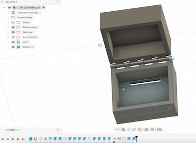
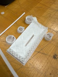
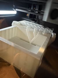
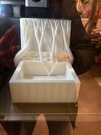
7.2 Box Architecture
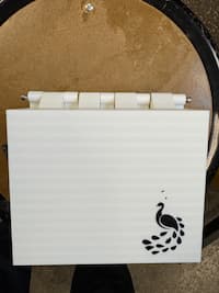
To manage these constraints, I designed the enclosure as a three-layer box. The bottom layer serves as the structural base and supports the main PCB. The middle layer houses the lotus LED PCB, because I wanted the lights to shine from there once you open it. It also has the mic, and a hole for all the wires to connect. The top layer functions as the lid and user-facing surface, exposing the lid PCB, buzzer, and eventually if I'd chosen to go that route, the OLED. A traditional shruthi box doesn't open like this, but I thought this form factor was intuitive - sort of like a laptop.
This layered approach allowed me to separate concerns: structure, electronics, and interface. It also made assembly and debugging significantly easier, since individual layers could be accessed without disassembling the entire system.
7.3 CAD Design (Fusion)
The enclosure was modeled in Fusion, with dimensions driven directly by the size and mounting requirements of the PCBs. Cutouts and internal clearances were iteratively adjusted to ensure that boards could be installed, connected, and removed without excessive force. I was SUPER helped by following a Youtube tutorial on how to design hinges on boxes, with a lot of support from Gert, Harrison, Rodrigo: See here
Particular attention was paid to tolerances around connectors, cable exits, and the alignment between layers so that the box would close neatly once assembled. Several iterations were required to balance internal accessibility with a clean external profile
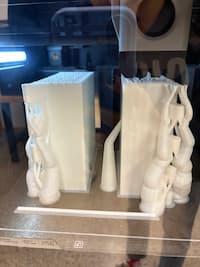
I made 2 versions:
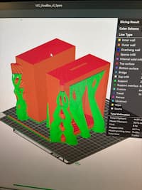
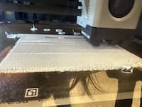
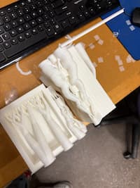
7.4 Fabrication & 3D Printing
The enclosure components were fabricated using 3D printing. Multiple prints were required to refine fit, especially because the printers were being a tiny bit finicky + I messed up on a couple design counts, including forgetting to put holes in the knuckle. These iterations revealed small but important mismatches between digital models and physical reality, reinforcing the need for test prints when designing enclosures around electronics.
The final enclosure successfully houses all electronics while maintaining a form that feels deliberate and aligned with the musical inspiration of the project.
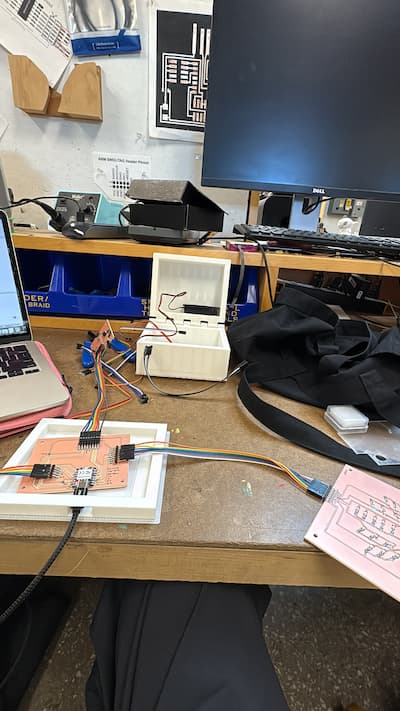
8. Final Assembly & System Integration
Even though assembly was a bit last minute, it went smoothly. I chose the second box (with the separate prints), but unfortunately had forgotten to drill holes in the alternate knuckles, so used a drill to do so manually and then used 2 thin screws to support the hinges when my 3d printed roller pin didn't fit. Also, I used some electrical tape to hold wires down - they're bendy but also quite stubborn/flip back to their orientation frequently. In future, even if I want to reveal the wires, maybe I would design little holders/shelves to force them into certain orientations? Or choose shorter wires?
9. Aesthetics & Finishing Touches
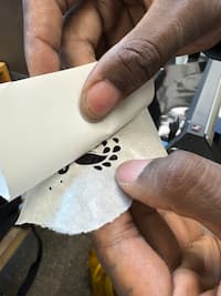
The biggest aeshetic elements were printing a really thin lotus to enclose the LEDs, putting it on a laser cut sheet of acrylic to diffuse the light. And then I also vinyl cut a sticker of a peacock to put on top of the box with Shah's help.
10. Future Work & Next Steps
If I were to continue with this project, I would include the OLED, design a laptop interface to view the singing in real time (perhaps), and then try this with a couple of different ragas, not just Mayamalava Gowla. Perhaps Kalyani or Sankarabharana. It would be interesting to see how the device flips between allowable frequencies in different ragas. Maybe in a future version, you could sing a riff to it and it could identify the raga (sort of like Shazam for Carnatic)!
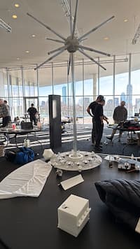
11. Behind the Scenes
Here are some fun no-context pictures. Maybe the real fab lab is the friends we made along the way...
Done. Thank you Gert for helpful advice, including naming this "SitarHero", and telling me to breadboard it before milling the PCB so I can see the electronics working.