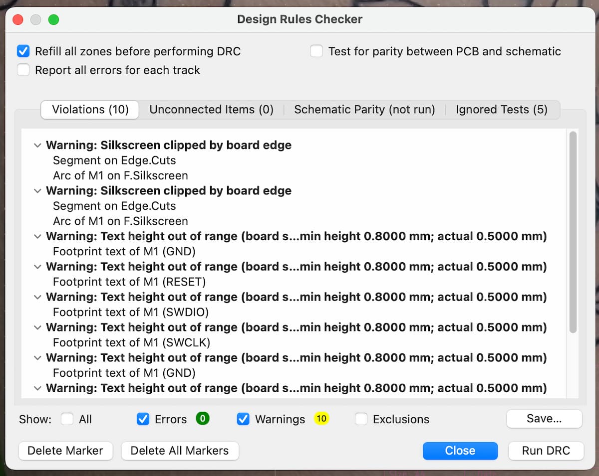
Use an EDA tool to design an embedded microcontroller system using parts from the inventory, check its design rules for fabrication, and simulate its operation
What does this mean —> An embedded microcontroller system is a small, specific for some purpose computer designed to perform task(s) within a larger device. Think of it as something that does one job really well; and think of the microcontroller as a brain. It’s a single chip containing:
So we’re trying to build a circuit board that holds the microcontroller and connects it to other components it needs to do the job. A circuit, as we know, is a complete path that electricity can flow through to accomplish something useful. To build one, we intentionally arrange a permutation of components, with each one playing a role in the overall function.
A PCB is a Printed Circuit Board. It has a substrate (non-conductive material) that forms the base, copper traces (conductive pathways, etched in, serve as wires between different components), components mounted onto it & soldered to points on the copper traces, solder mask (protective layer covering the traces), and silkscreen (layer of ink that labels components etc.) PCBs are found in every single thing: computers, smartphones, TVs, microwaves.
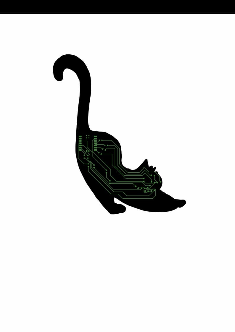
I learnt that PCBs can be any shape as long as the electrical parts work. So I would like to make a **glowing Cheshire Cat PCB** (in celebration of insanity, my tattoo, and complete disregard for the rules of physics - which I think is funny in this particular week)

| Term | Definition |
|---|---|
| Ribbon cable / connector | Physical ways to connect your board to other things. |
| Resistor | Limits current flow, sets voltage levels (voltage = potential difference that pushes electrons through a circuit, measured in volts). |
| Capacitor | Stores electrical charge temporarily to smooth out any voltage fluctuations (think of it as a temporary battery). |
| Resonator | Creates precise timing signals (like a clock). |
| Inductor | Stores energy in a magnetic field. |
| Diode | Allows current to only flow in one direction. |
| Transistor / MOSFET | Electronic switches controlled by voltage (MOSFET is one type of transistor). |
| Microcontroller | The brain. Has just enough processing power for simple, repetitive, power-conscious tasks — found in embedded systems like home appliances. |
| Microprocessor | Has a CPU and requires external components for memory etc. Higher-performance, for complex tasks and general computing (PCs, laptops, servers). |
| Sensor | Measures something like temperature or light. |
| Battery | Power source. |
| XIAO RP2040 | RP2040 is the chip (designed by Raspberry Pi); XIAO is a tiny development board that includes the chip, a voltage regulator, USB connector, and pins. |
| Net | Symbolizes a logical electrical connection in KiCad; wires on the PCB are the physical embodiment of nets. |
| SMB | Surface Mount Board (opposite: through-hole). |
A symbol/schematic is the abstract, logical representation of the circuit - like the parallel lines for a battery, zigzag lines for a resistor. It’s agnostic to the physical size/shape. The **footprint** is the actual PCB layout with precise dimensions in millimeters. So, we:
Best practice:
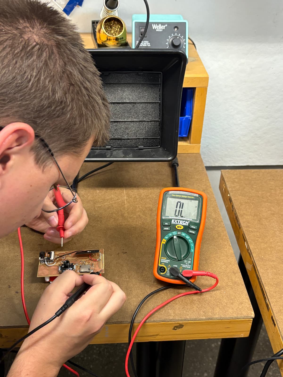
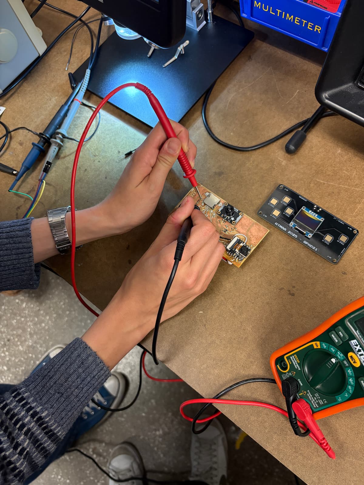
In this week's lab session, the focus was on learning how to safely use test equipment to analyze the operation of an embedded microcontroller. Safety was the highest priority, especially since variable power supplies can deliver voltages up to 20V — although this level is generally safe to touch, caution is recommended and typical projects use lower voltages between 3-5V. Understanding the basic electrical terms was essential: voltage refers to the amount of power delivered to specific points in the circuit, while current (measured in amps) can be imagined as the width of a pipe that allows more or less electrical flow, and resistance represents anything that obstructs this flow. The canonical relationship V=I/R (Ohm’s Law) governed all measurements during the lab.
A multimeter was employed to diagnose board issues by measuring voltage and resistance across various points in the circuit. This instrument helps check for continuity—confirming that electrical paths are intact and working—by placing its probes at two points and listening for a sound signal when in continuity mode. Observing these signals and using the multimeter correctly helped establish whether problems were present in the microcontroller setup.
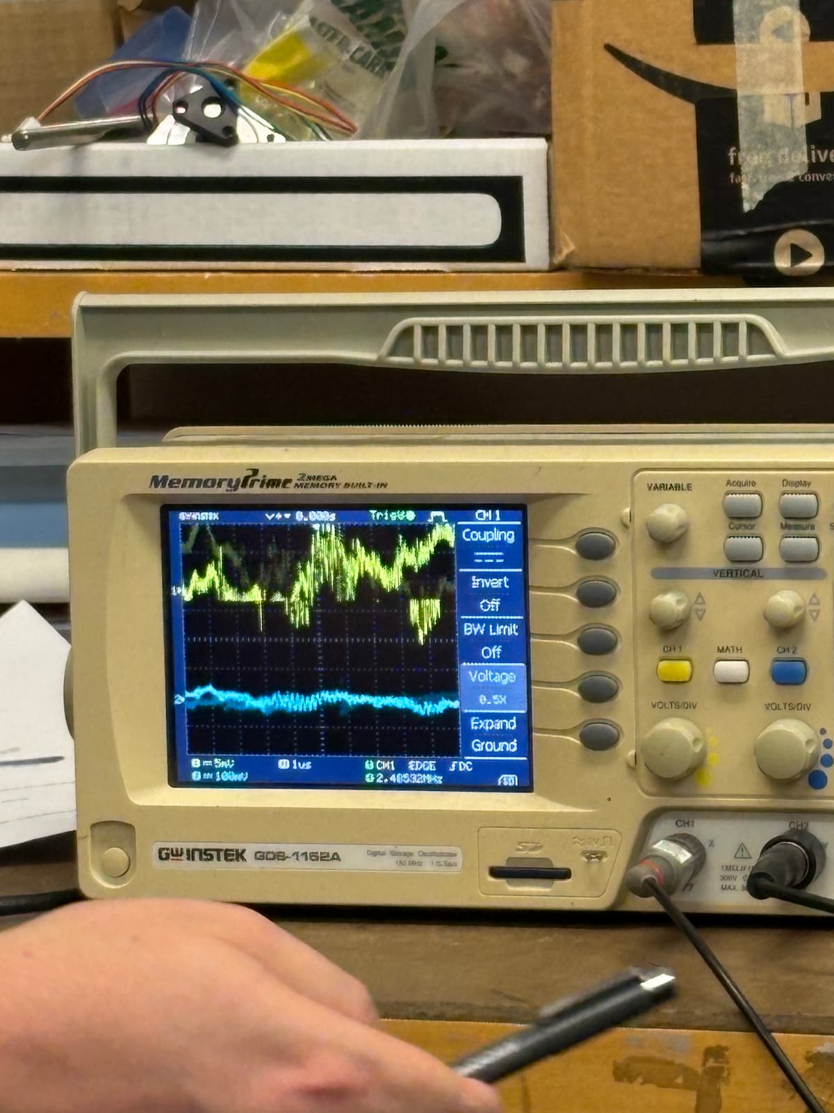
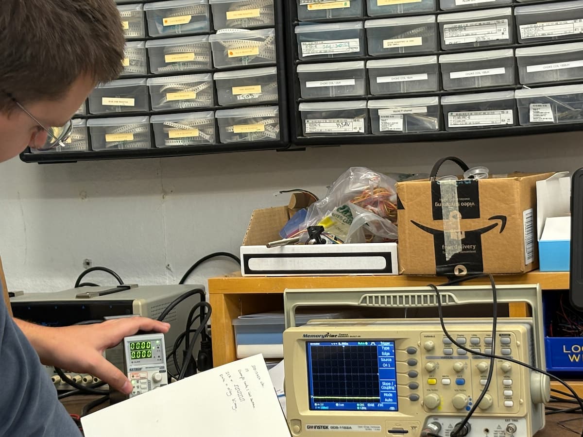
We also used an oscilloscope, which visually tracks voltage over time, enabling analysis of electrical noise (the fluctuations or irregularities in voltage) and the stability of voltage signals coming from the microcontroller. Using the single-shot capture feature, it was possible to freeze the screen and get a snapshot of the signal for detailed inspection, and to verify if data was being transmitted as binary signals by observing clear digital pulses on the display. The oscilloscope was especially useful when comparing how signals behave with different power supply types: linear power supplies convert AC to DC using transformers and regulators for a stable, low-noise output, while switching power supplies produce more noise and are common in modern electronics.
An important concept throughout the lab was “ground,” which serves as the baseline reference for measuring voltage variations in electronic circuits. Understanding where and how to reference ground enabled more accurate and consistent measurements.
Some fun notes: for at least 30 mins into the group tutorial, I didn't catch the word "oscilloscope" and thought we were saying "a sillascope".
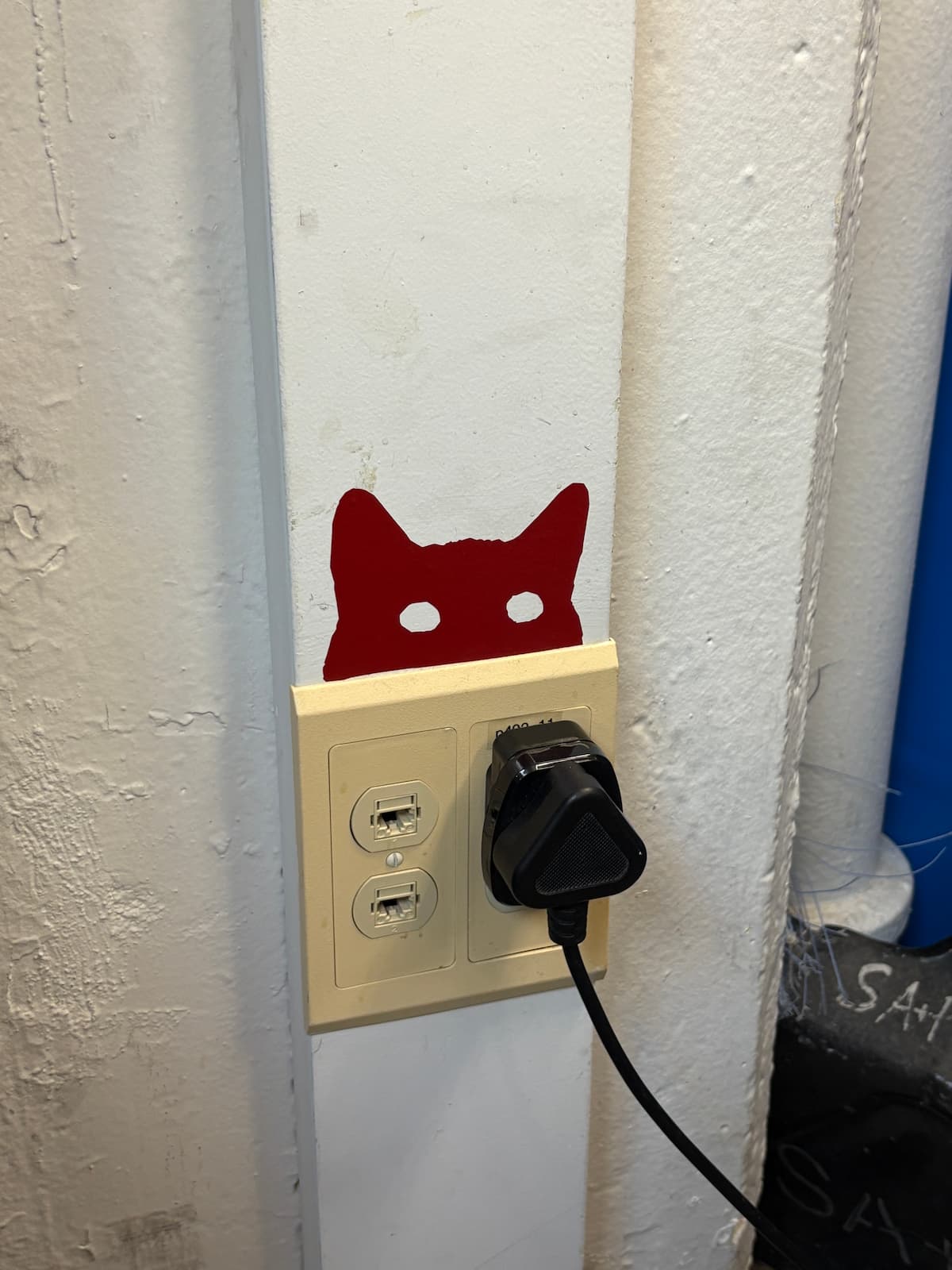
Also, hello and thank you to this highly topical lab cat.
Since I have never in my life made a circuit -- or indeed, spent time looking at a circuit board -- I decided to do this week sequentially.
First I started by just following Quentin's recitation tutorial and recreating that simple microcontroller system + familiarizing myself with KiCad.
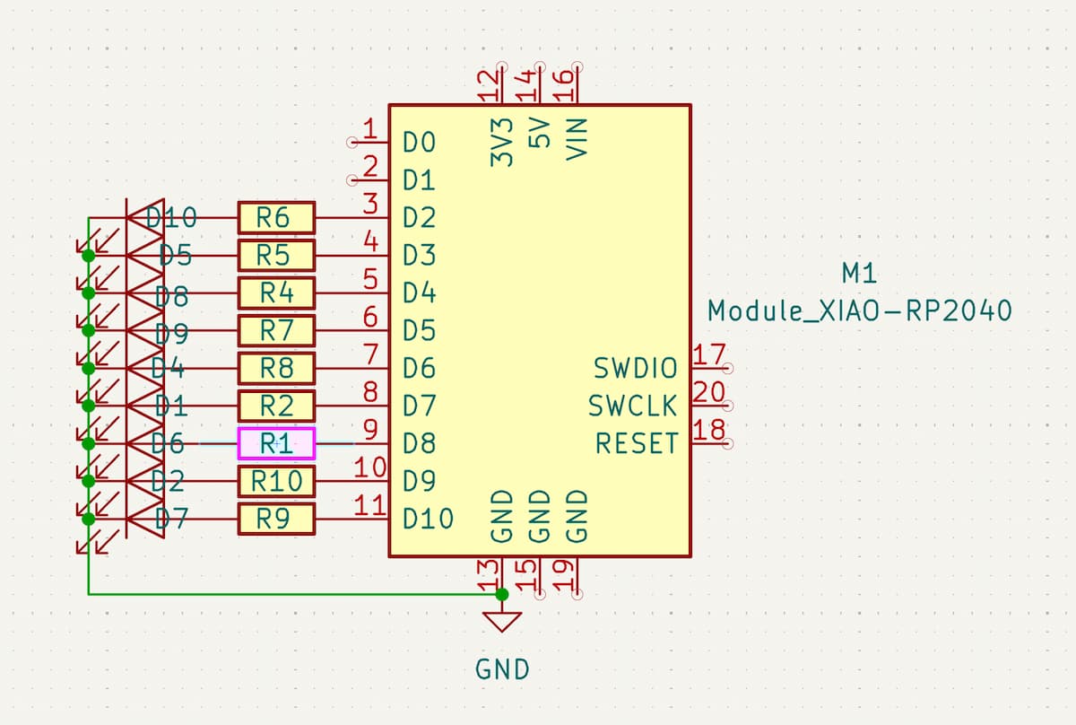
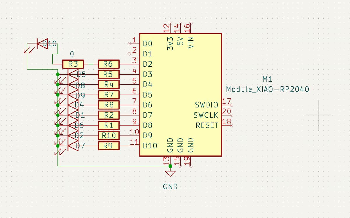
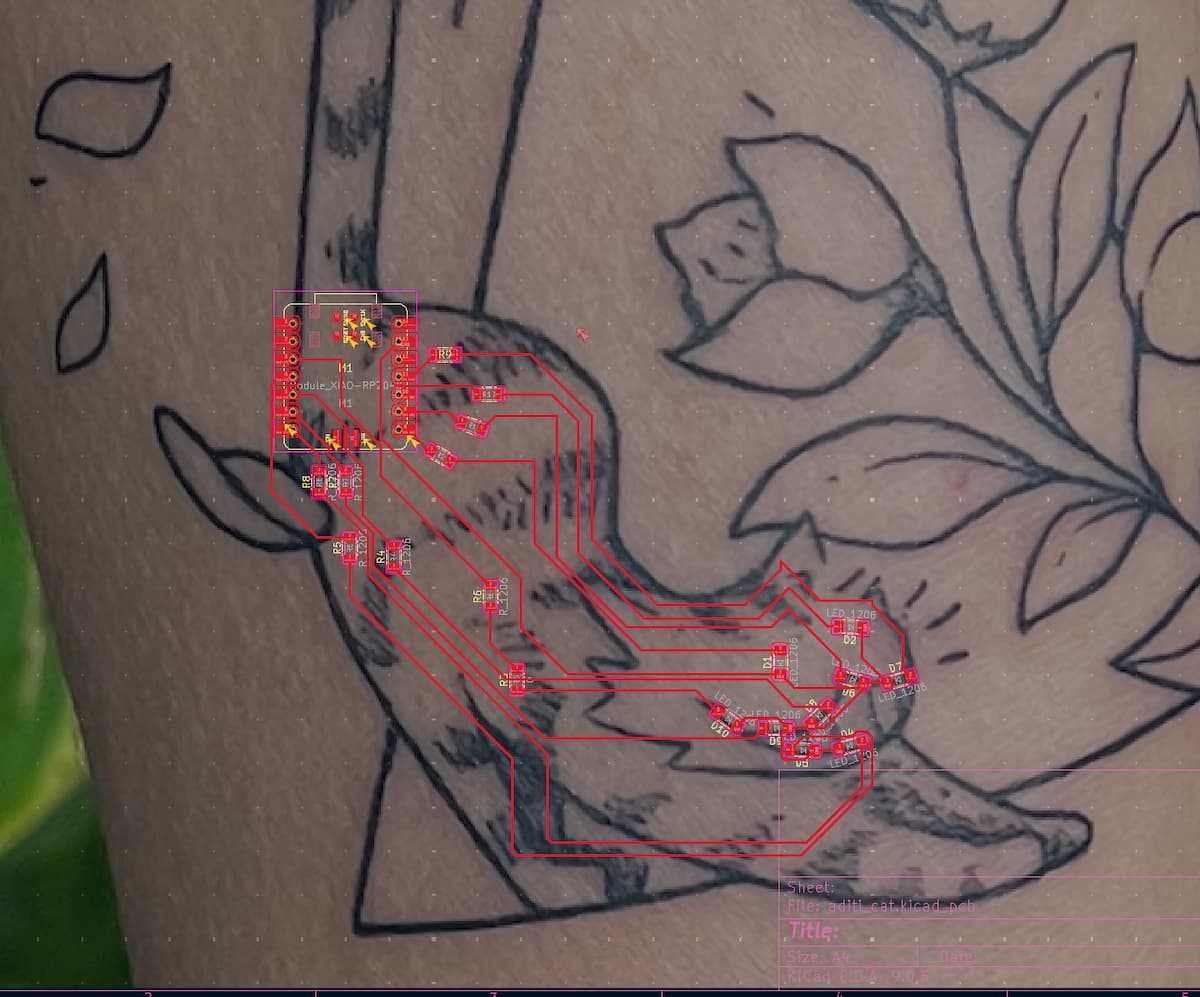
Then I started to ideate on a very simple circuit with 9 LEDs placed within my cat tattoo body. The idea was 9 LEDs (which is ok since the XIAO RP2040 has 11 pins), each with a resistor, and connected to ground. So: XIAO <> resistor <> LED <> ground. I placed the lights along the eyes and grin of the cat.
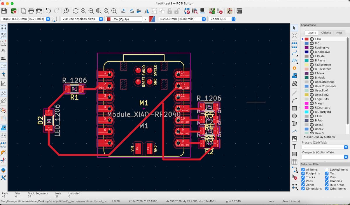
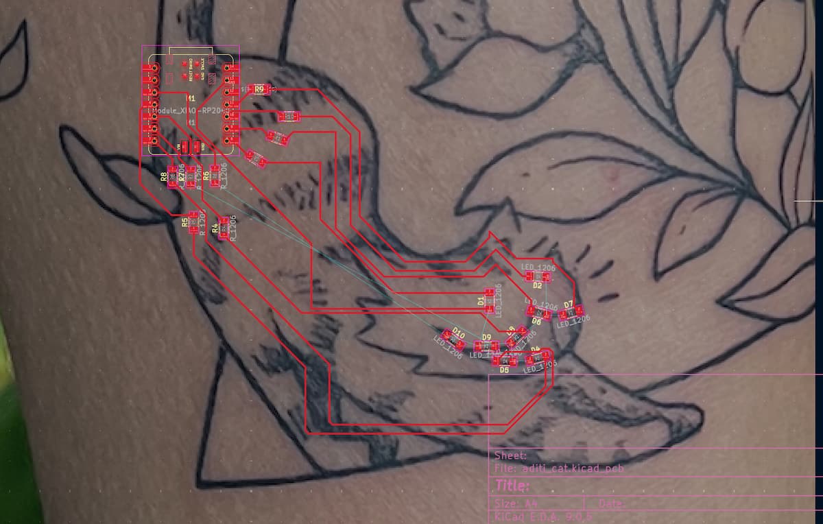
To do this, I (somewhat lazily) imported a bitmap of my tattoo as a "reference image" (a feature in the board view of KiCad). This won't show up in any output. Then, I placed the LEDs where I wanted them (using the E key to position them at the angle I wanted). Then I had the topographical adventure of my life trying to connect them to ground and to the resistors.
This didn't work that well and it took me ~2 hours to figure out the topography. Learnings:
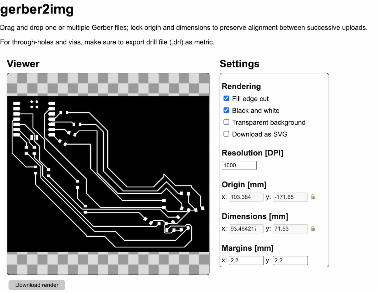
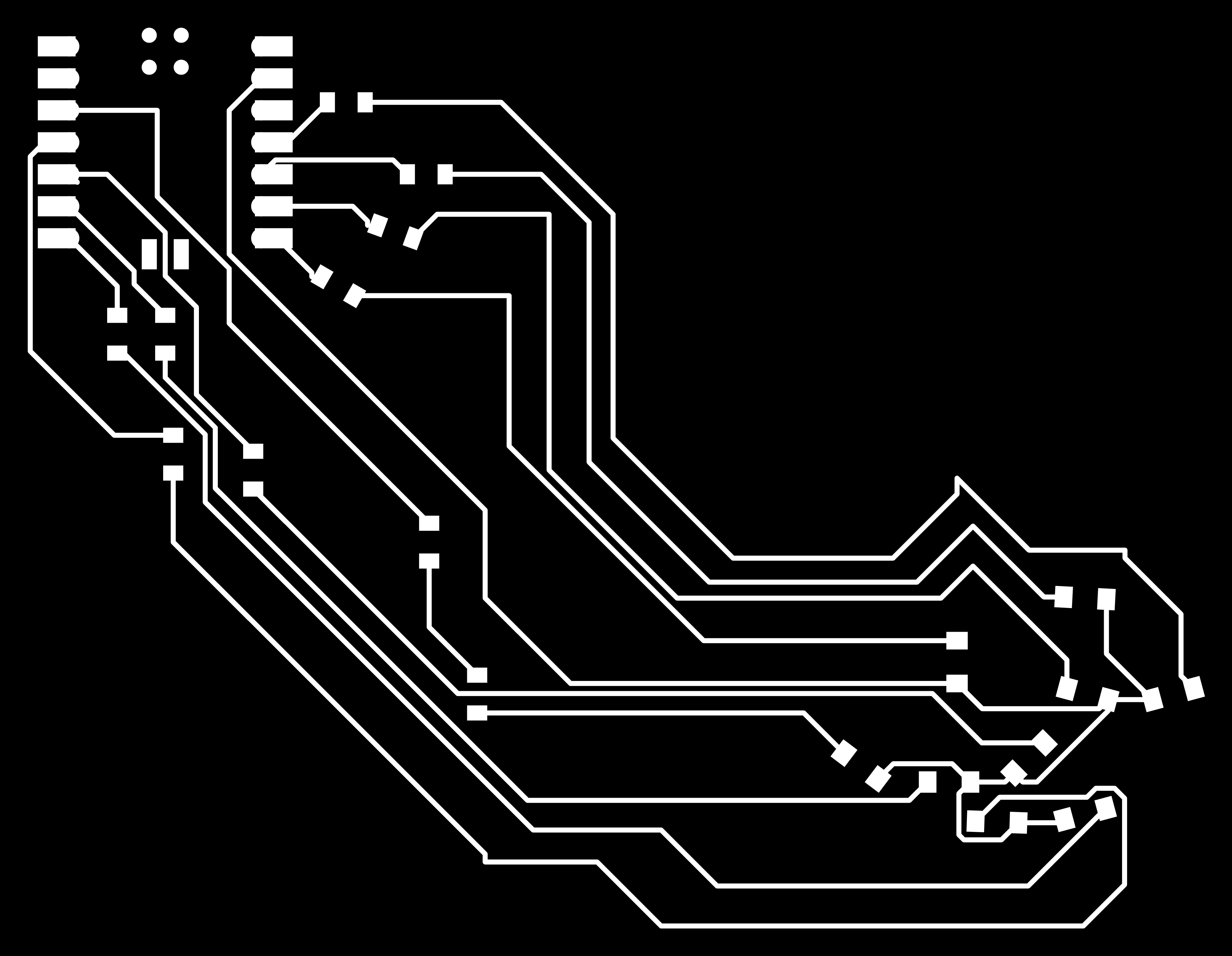
Then I used Quentin's gerber2image tool to convert this into a transparent, b&w png, and then used Inkscape to superimpose it onto an svg of the cat that I drew myself (tracing the original tattoo design).