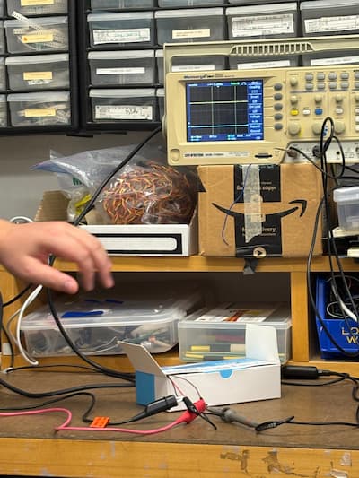
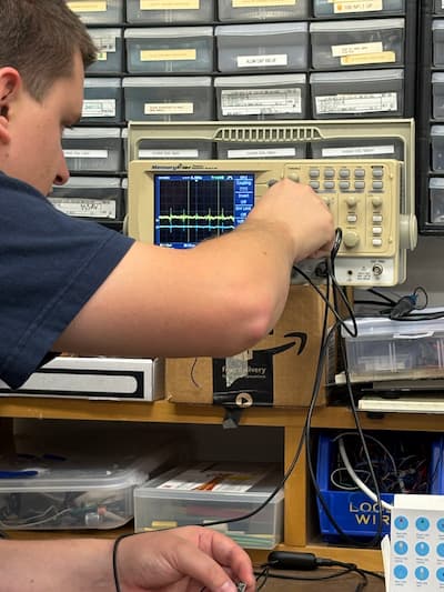
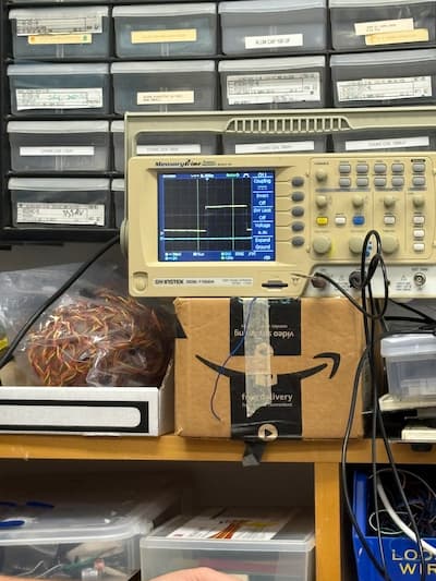
This week in "How to Make Almost Anything," our group investigated input devices by probing the analog and digital signals of a motion sensor. Using an oscilloscope, we monitored how movement affects the sensor’s output voltage: the yellow trace on the scope drops low when we remain still and quickly jumps high when motion is detected. The blue trace serves as our ground reference, letting us see the sensor’s voltage changes relative to a constant baseline—just like checking depth against sea level. Our setup included connecting the sensor’s power and ground, tying its output to the oscilloscope’s silver probe, and ensuring everything was referenced to a shared ground for accurate readings.
One intriguing observation was the sensor’s ability to detect motion even when concealed inside a box. We also explored how a separate clock signal—involving another pin—can represent digital signals, with its voltage cycling up and down over time. With each movement, we noticed a one to two-second lag before the voltage responded, highlighting both the sensitivity and delayed response characteristics of this input device. These measurements helped us understand how input devices translate real-world changes into readable electrical signals, which are crucial for designing interactive systems.
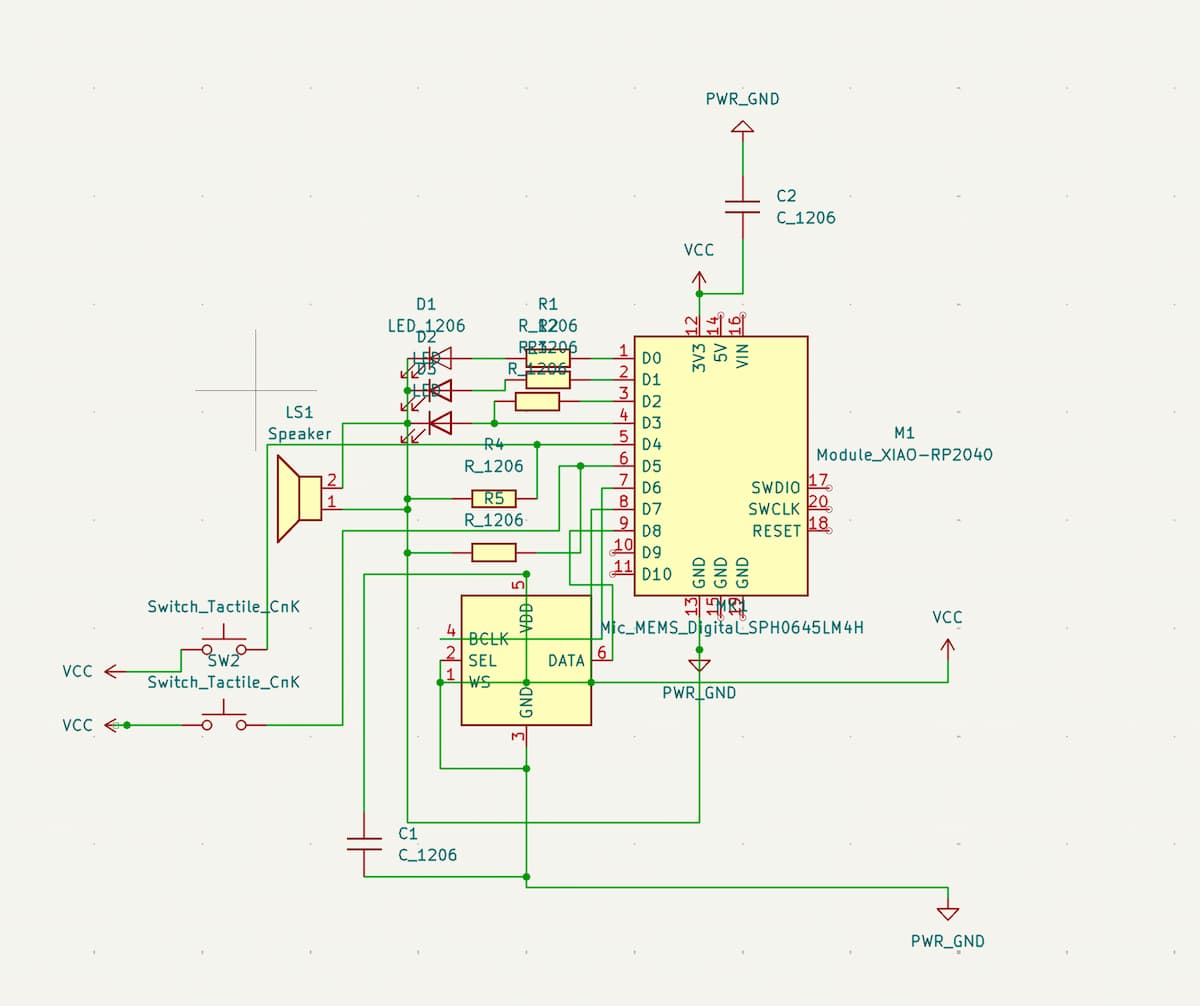
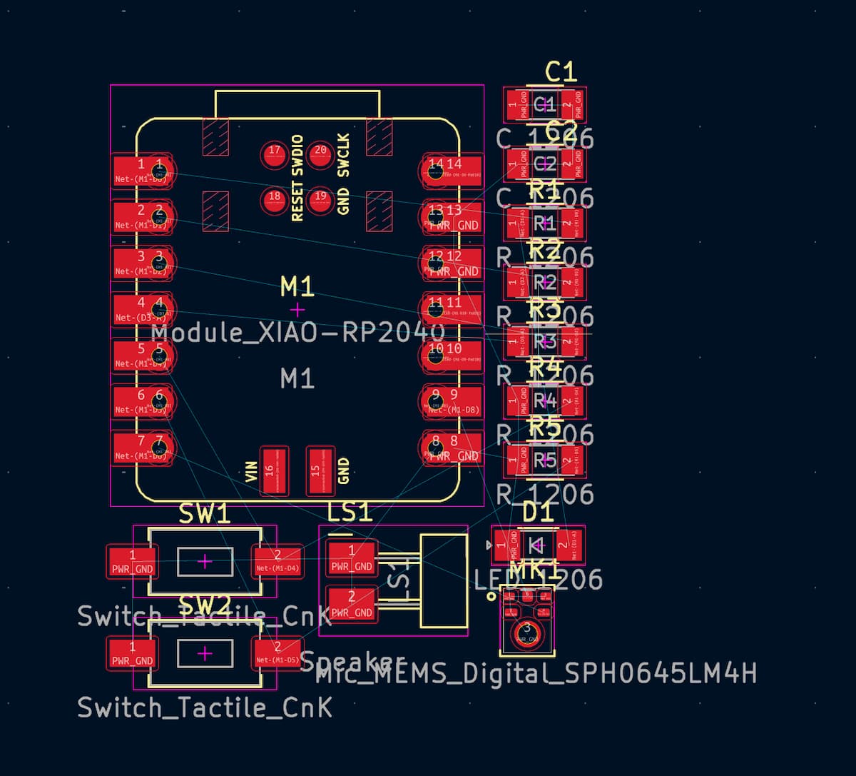
This week, my hope was to design a PCB that will work for both my input and output devices, that will help me make progress toward my final project. The inputs required are buttons and a microphone. The outputs are LEDs, a speaker (Piezo), and hopefully an I2C OLED display.
But I ran out of time to validate whether my schematic makes sense, even though I think I have the right component parts. Storing horrible screenshots below to revisit and compare next week:
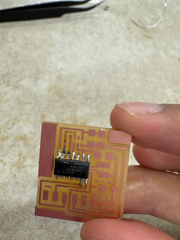
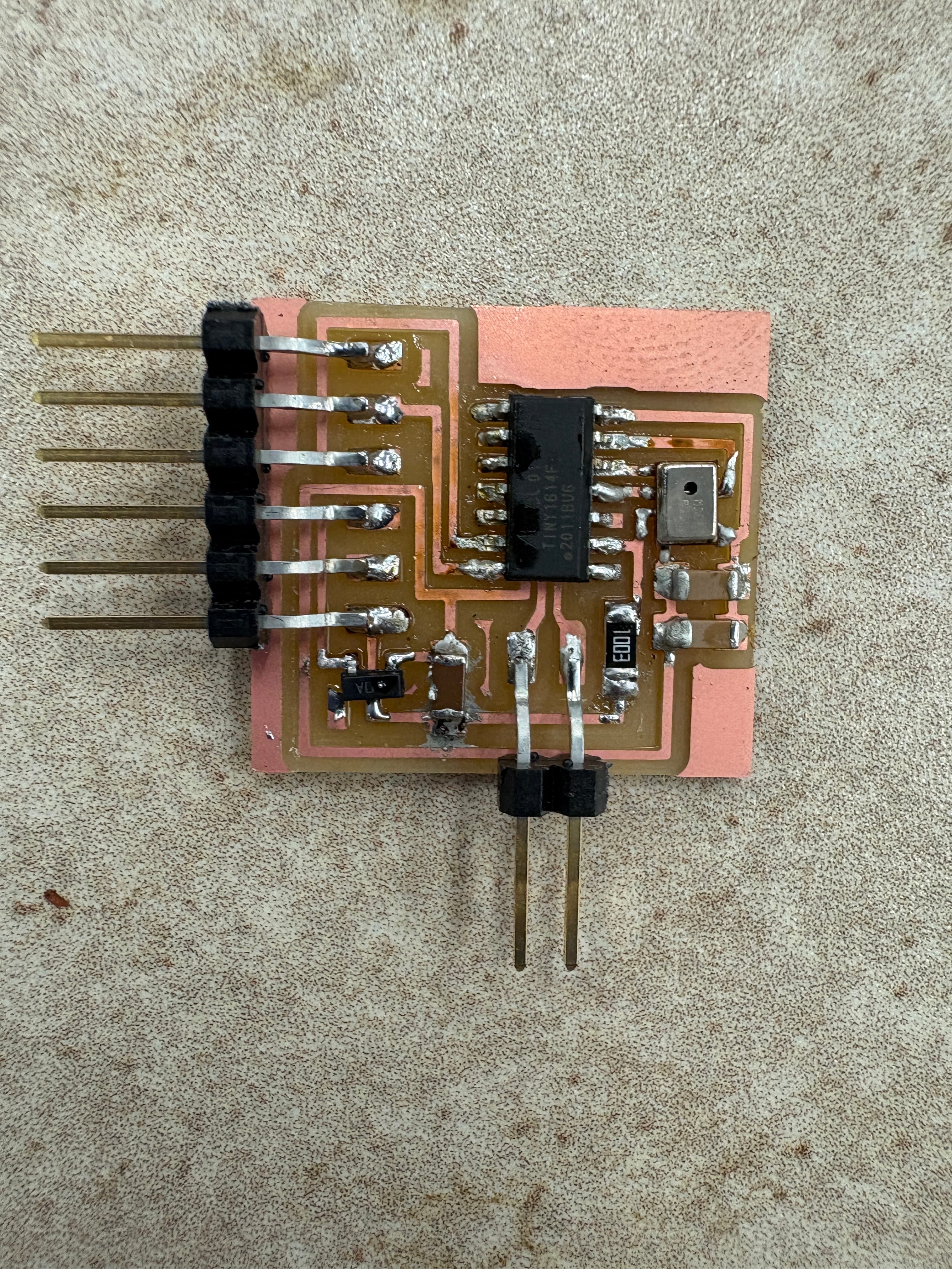
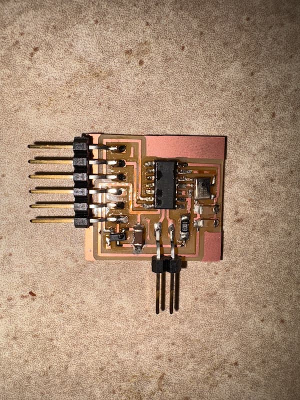
If you recall, I am quite bad at soldering:
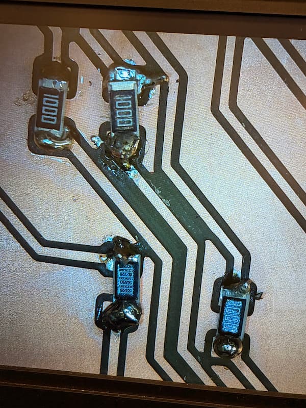
So I decided to use this week to replicate one of Prof. Gershenfeld's boards (the ones with a top port microphone) to test, and to practice soldering (and figure out how to actually do that). Enormous thank you to Anthony for the patience in teaching me this. Unfortunately, after soldering all the pieces I realized this wasn't a USB port connectable board, and I didn't have the cable available to send code to this.
My next move is to validate the schematic and editor, include any part sthat are missing, figure out the right design so that the board isn't too crowded/difficult to solder, will fit into the form factor I am intending, and then to solder all these parts together for testing during output devices week. My hope is to figure out the LED display part, since this will be a critical component of the final project.