On Thursday afternoon, our group spent some time with Gert in a session focused on the fundamentals of electronics. He walked us through practical examples. Using a stepper motor, he showed how changing the input voltage directly affects how the motor behaves, from how smoothly it runs to how much power it draws. Seeing this relationship in real time made the tradeoffs between performance and energy use much easier to understand. He followed this with a simple demonstration using an LED. By slowly increasing the voltage past what the component was designed to handle, he illustrated what happens when electrical constraints are ignored. The LED eventually failed and burned out — a small but effective reminder of why respecting component limits is critical when designing and testing electronic systems.
I decided to start working toward my final project this week, which is very output-device heavy. You can see more info on my final project in the pages labeled week 1 and final project.
For my final project, the output devices are central to how the user (me, while practicing music) receives feedback in real time. Since the goal of the device is to act as a raga alignment checker, the outputs needed to be intuitive, low-latency, and minimally distracting while singing.
I implemented two output devices:
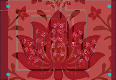
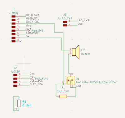
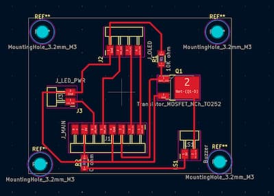
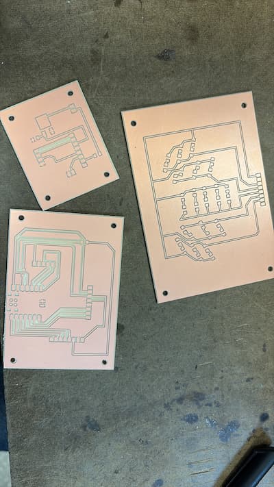
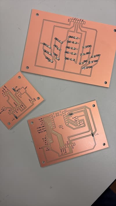
The project uses three custom PCBs:
The LED board provides immediate, glanceable visual feedback while singing. The goal is not to show exact pitch or frequency, but to gently guide the singer toward staying within the allowable notes of the raga.
Each color communicates a different state:
The symmetrical, flower-like arrangement was intentional — the LEDs act as a peripheral cue rather than something that demands constant visual attention.
Once pitch detection is running (via the microphone input), the system evaluates pitch continuously and maps it to LED states.
To reduce visual noise and overstimulation:
This smoothing logic ensures that fast melodic runs do not cause frantic or distracting color switching.
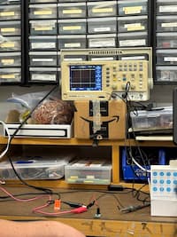
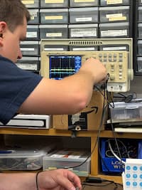
Before integrating audio-based logic, I wrote simple test code to validate the LED board independently.
This helped isolate hardware issues early, before layering in pitch detection and signal processing.
// ===== LED pin definitions =====
#define RED_RIGHT  0   // D0
#define YEL_RIGHT  1   // D1
#define GREEN_LED  2   // D2
#define YEL_LEFT   3   // D3
#define RED_LEFT   10  // D10

int leds[] = {
  RED_RIGHT,
  YEL_RIGHT,
  GREEN_LED,
  YEL_LEFT,
  RED_LEFT
};

void setup() {
  Serial.begin(115200);
  delay(1000);
  Serial.println("Starting LED hardware test");

  // Set LED pins as outputs
  for (int i = 0; i < 5; i++) {
    pinMode(leds[i], OUTPUT);
    digitalWrite(leds[i], HIGH); // OFF (active-low)
  }
}

void loop() {
  // Step through each LED group
  for (int i = 0; i < 5; i++) {
    Serial.print("Turning ON LED group on pin D");
    Serial.println(leds[i]);

    digitalWrite(leds[i], LOW);   // ON
    delay(800);

    digitalWrite(leds[i], HIGH);  // OFF
    delay(300);
  }

  // All on
  Serial.println("ALL LEDs ON");
  for (int i = 0; i < 5; i++) {
    digitalWrite(leds[i], LOW);
  }
  delay(1500);

  // All off
  Serial.println("ALL LEDs OFF");
  for (int i = 0; i < 5; i++) {
    digitalWrite(leds[i], HIGH);
  }
  delay(1500);
}
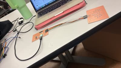
The buzzer provides audio feedback only when necessary. Because this is a music practice device, the buzzer is intentionally restrained so that it acts as a guardrail rather than a constant interruption.
I wrote and ran simple test code to validate the buzzer circuit.
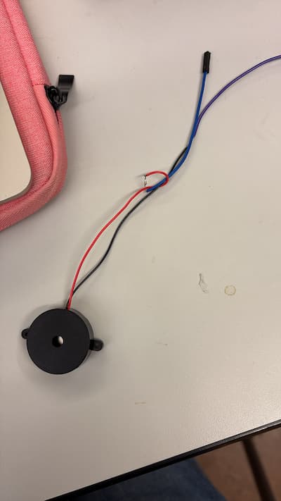
The original buzzer I was using (a piezo) was so faint that I couldn't hear anything. I asked Anthony to help troubleshoot, and he realized it was playing audio: just that you could only hear it if you held the buzzer to your ear. This wouldn't work, so we looked at a few louder alternatives:
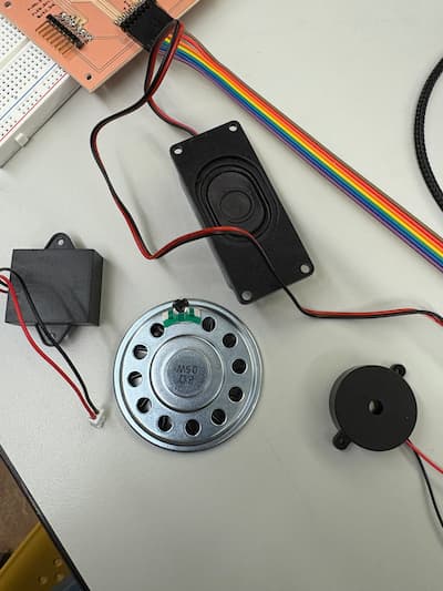
The first one actually allowed me to try a new kind of soldering. I used pliers to remove some of the plastic casing, and then twisted that to a jumper wire and soldered the two together.
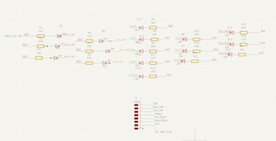
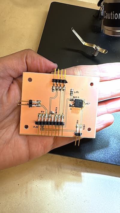
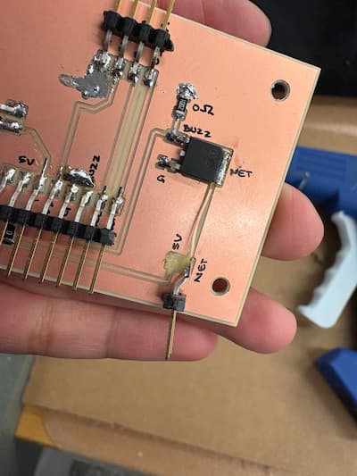
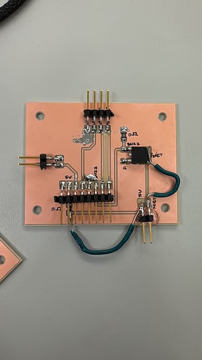
When assembling the LED board, I initially soldered all the LEDs in the wrong orientation, connecting the cathode to the resistor instead of the anode. But as you can see from the schematic - the anodes connect to the resistors, and cathodes to the nets. This was a very irritating error. I think I was so nervous about soldering (something I used to be bad at) that I quickly just googled "what to connect to resistors" just to start, without critically thinking for myself.
While time-consuming, this reinforced the importance of verifying component orientation before soldering. And of not being an idiot and letting fear take over critical thinking.
While handling the lid board, I accidentally ripped off the 2-pin header connecting the buzzer to the board. Anthony warned me about this since 2 pin headers are delicate -- I tried to avoid this issue, but momentarily lost control.
Note: the final code I used for these two is in my final project page.
Together, the LED board and buzzer form the primary feedback language of the device. Rather than displaying numbers or instructions, they communicate through color, timing, and restraint, which feels especially appropriate for a musical practice tool.
This stage of the project pushed me to think more intentionally about designing outputs that are informative without being overwhelming, and about debugging systems where hardware and software failures are tightly intertwined.