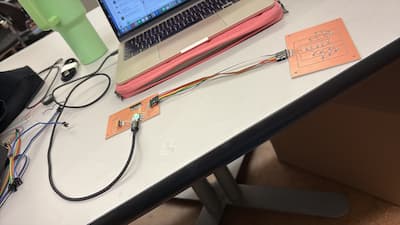
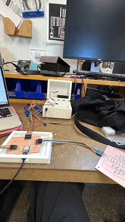
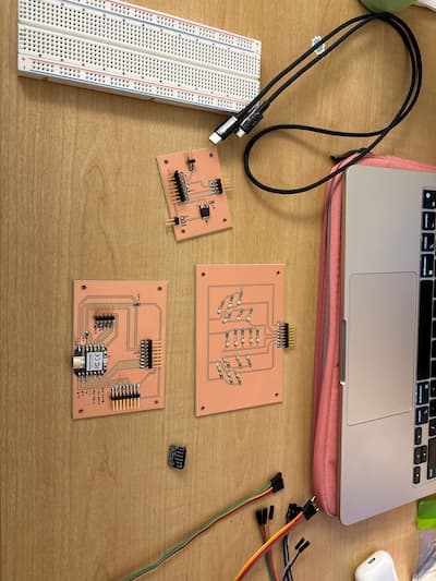
Again, I chose to work toward my final project this week. As you know, I'm choosing to use a network of 3 custom PCBs plus one Adafruit I2S, and it's critical they form an integrated network & communicate in real time with each other. Rough sketch of the idea (incomplete):
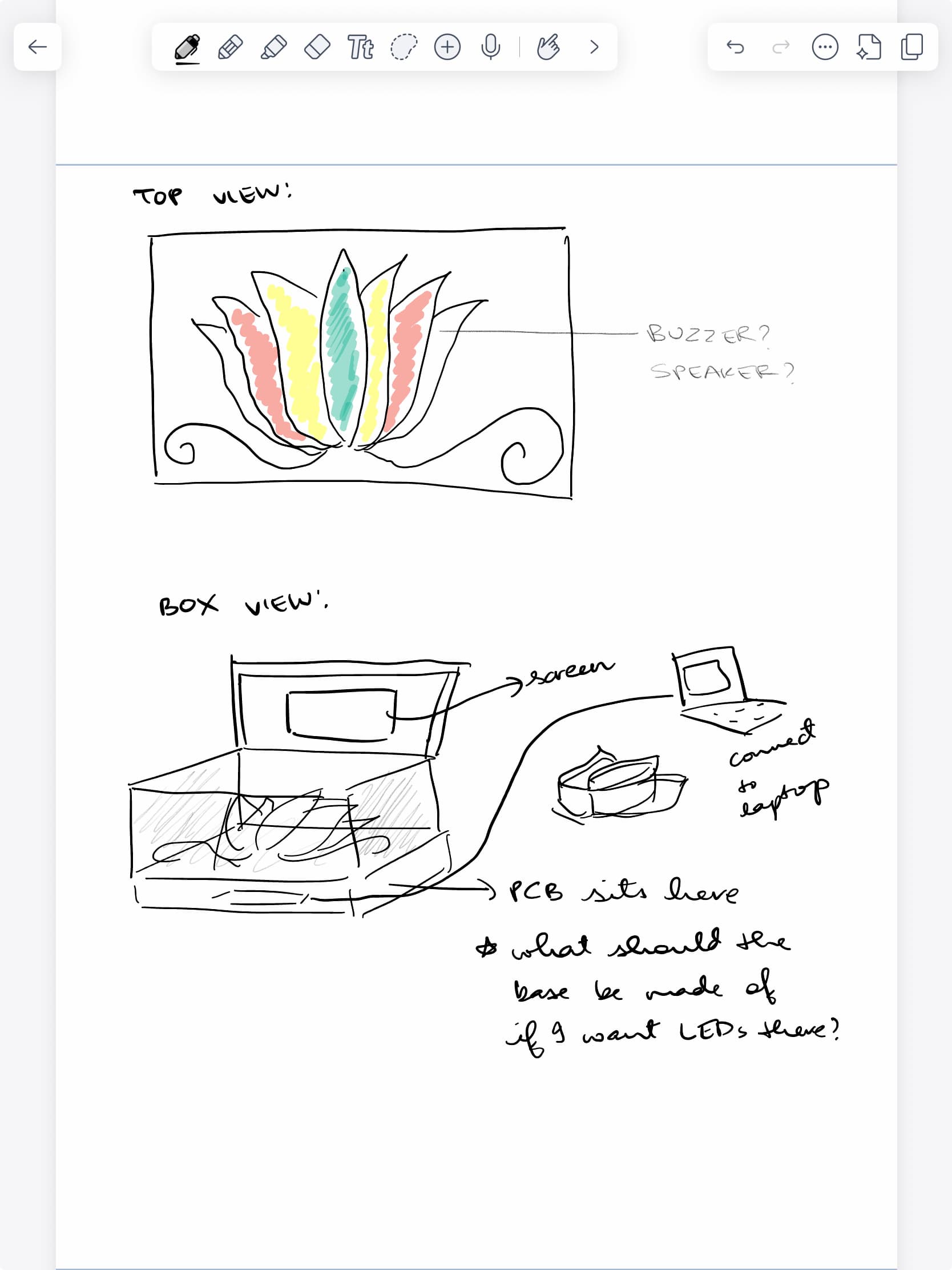
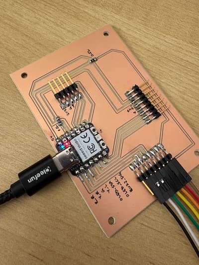
While my final project does not include wireless networking, it relies heavily on structured wired communication between multiple custom PCBs. The system is distributed across three boards — a main microcontroller board, an LED board, and a lid board — which communicate through dedicated connectors carrying power and control signals. This separation allowed me to modularize the system, physically distribute components within the enclosure, and test subsystems independently before integration.
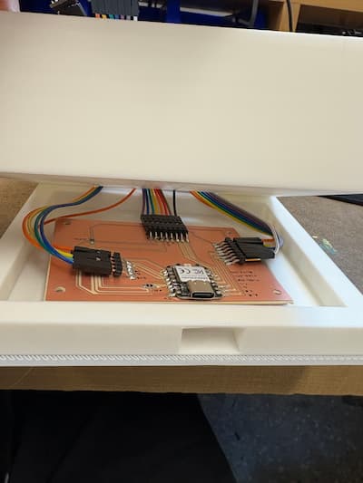
Note: I made the intentional choice to keep these colorful jumper wires, and designed the box around their existence. I really liked the contrast of the rainbow colors against a plain white box: it symbolizes Carnatic music quite nicely in my head.
/*
   I2S stereo microphone (input) example
   Run using the Arduino Serial Plotter to see waveform.
   Released to the Public Domain by Earle F. Philhower, III

   For the Google AIY Voice Hat Microphone daughterboard, part
   of the Raspberry Pi AIY cardboard box, the I2S stereo pinout
   looking at the board top with the RPI logo on the left hand
   side:
            +--   ------------------------------------  --+
   left RPI | (1) GND (2) DIN (3) BCLK (4) LRCLK (5) 3.3V | AIY right
       logo +---------------------------------------------+ logo

   For an Adfruit I2S MEMS microphone (https://www.adafruit.com/product/3421),
   connect the pins as follows:

      DOUT -> GPIO0
      BCLK <- GPIO1
      LRCL <- GPIO2  # LRCLK = BCLK + 1
      GND <-> GND
      3V  <-> 3V3OUT

   The other idiosyncrasy of most modern MEMS microphones is that they
   require a minimum clock rate to wake up. For example, the SPH0645
   microphone needs at least 1MHz.
*/

#include

I2S i2s(INPUT);

void setup() {
  Serial.begin(115200);

  i2s.setDATA(D9);
  i2s.setBCLK(D7); // Note: LRCLK = BCLK + 1
  // i2s.setBitsPerSample(16);
  // i2s.setFrequency(22050);
  // NOTE: The following values are known to work with the Adafruit microphone:
  i2s.setBitsPerSample(32);
  i2s.setFrequency(8000);
  i2s.begin();

  while (1) {
    int16_t l, r;
    i2s.read16(&l, &r);
    // NOTE: Adafruit microphone word size needs to match the BPS above.
    // int32_t l, r;
    // i2s.read32(&l, &r);
    if(l!=0){
    Serial.printf("%d\r\n",  l);
    }
  }
}

void loop() {
  /* Nothing here */
}
Please find this on the output devices page.
I tested this directly in my final project code, which you can find on that page.
This test code verified reliable signal transmission from the main board to the peripheral boards through the board-to-board connectors.
As you can see on my final project page, this code worked very well all together and my boards were able to communicate with each other as I needed them to! A nice next step would be to maybe find a wireless way to do some of the trickier communication, where the wire was folding dangerously.