week 6:electronics production
Jen's training
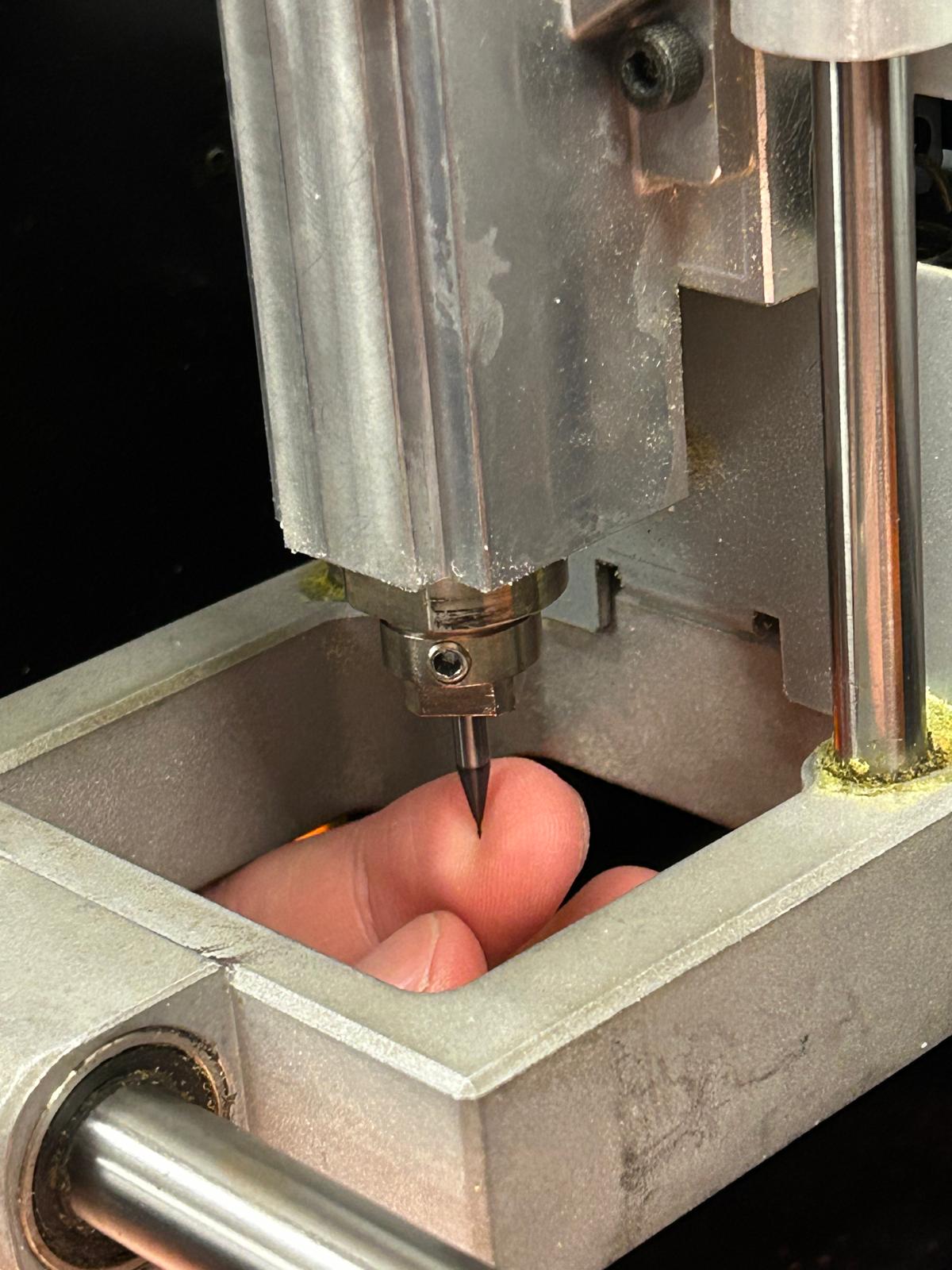
In this week's training, Jen provided a comprehensive overview of the electronics production process, covering key steps such as preparing the design files, selecting materials, and using the milling machine. She emphasized the importance of double-checking the design files for errors before production to avoid costly mistakes. Jen also demonstrated how to set up the milling machine, including loading the material, calibrating the tool height, and starting the milling process. Additionally, she discussed safety precautions to take while operating the machine and provided tips for troubleshooting common issues that may arise during production. Overall, Jen's recitation was informative and provided valuable insights into the electronics production process.
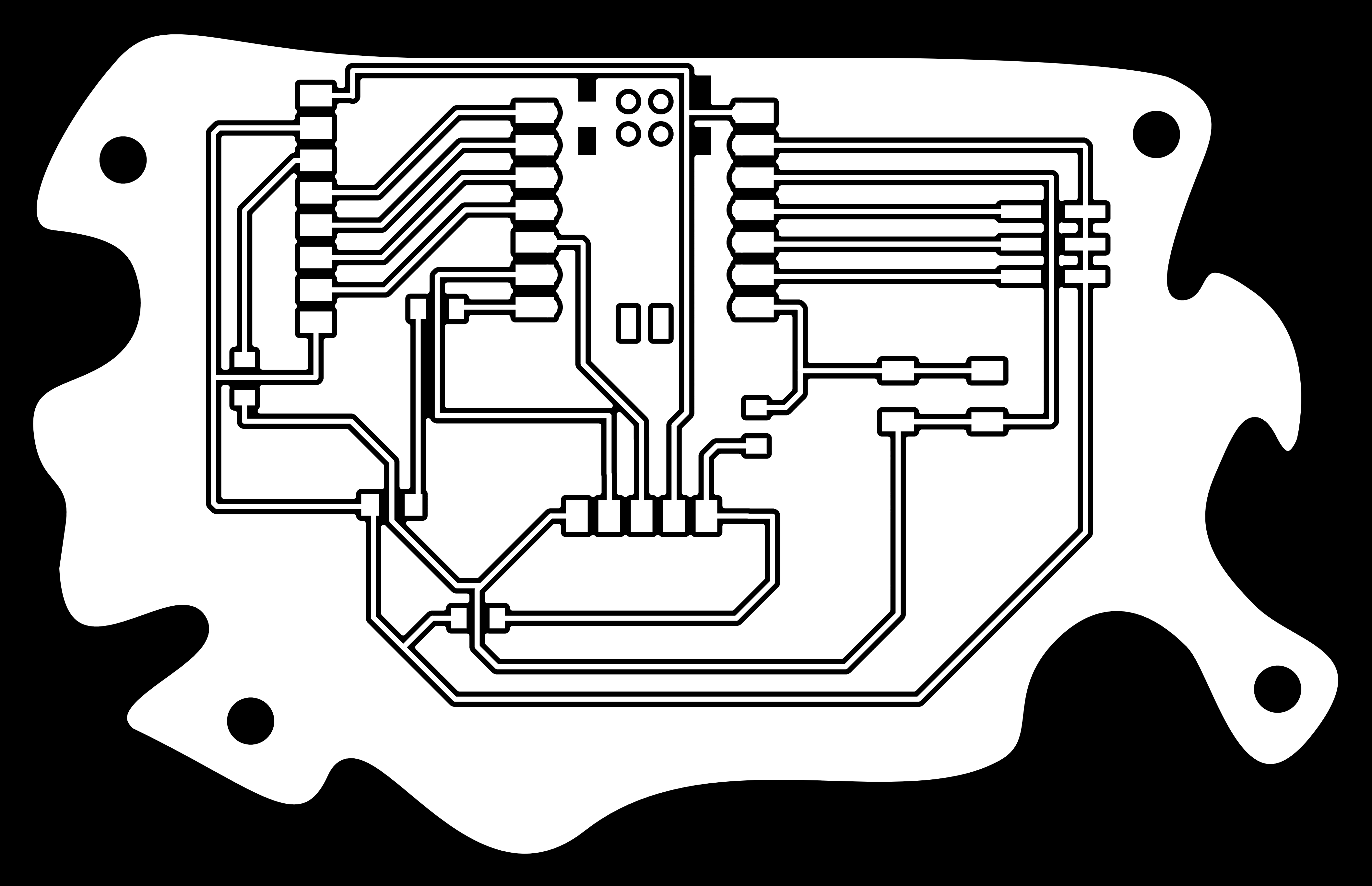
Last week's design
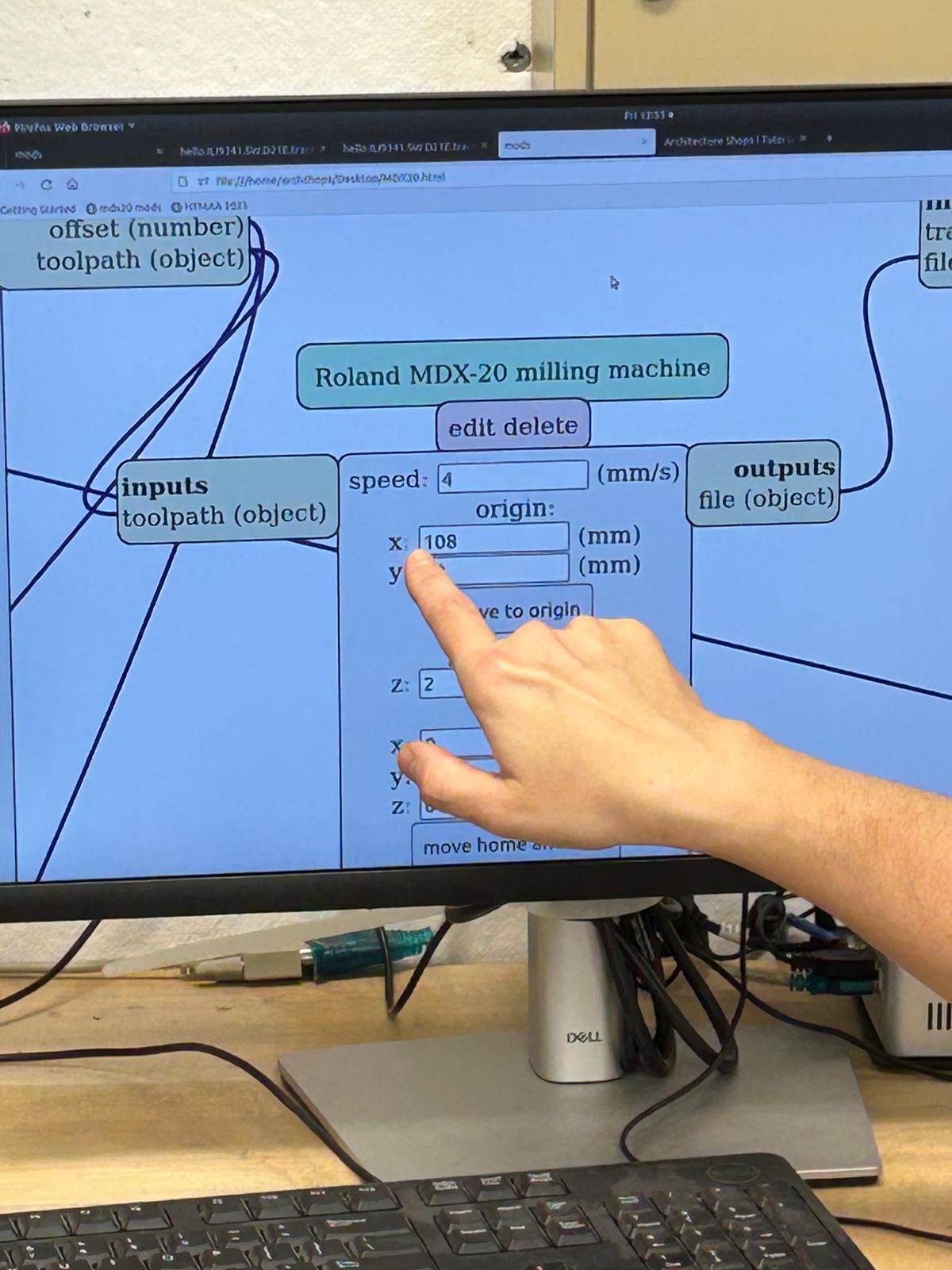
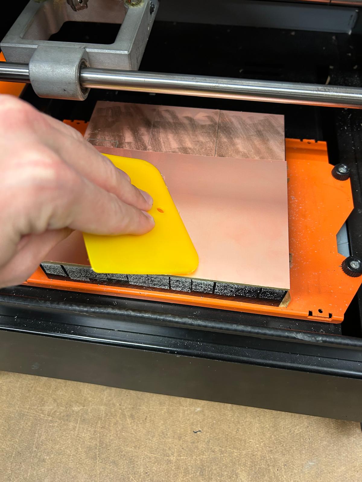
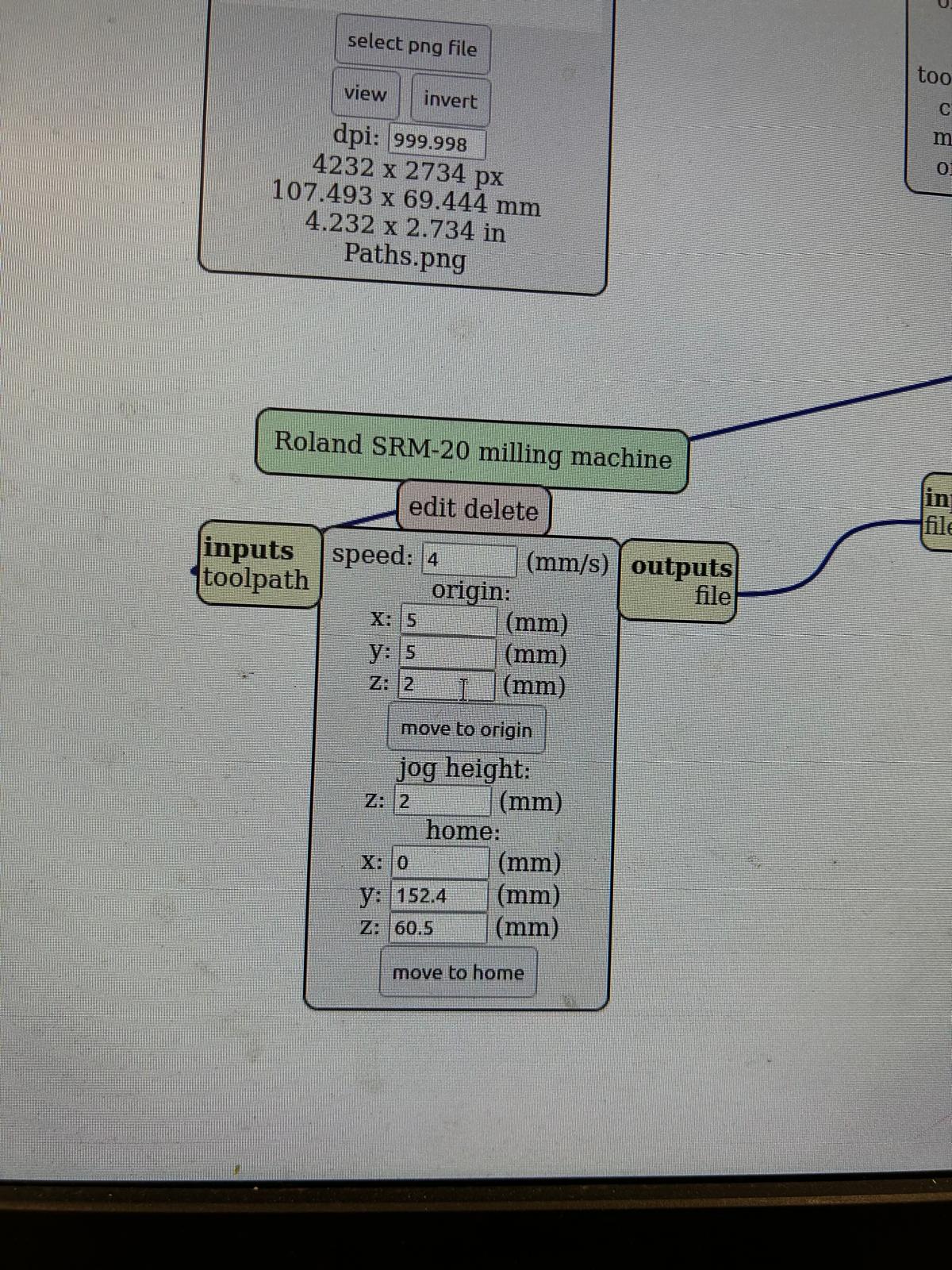
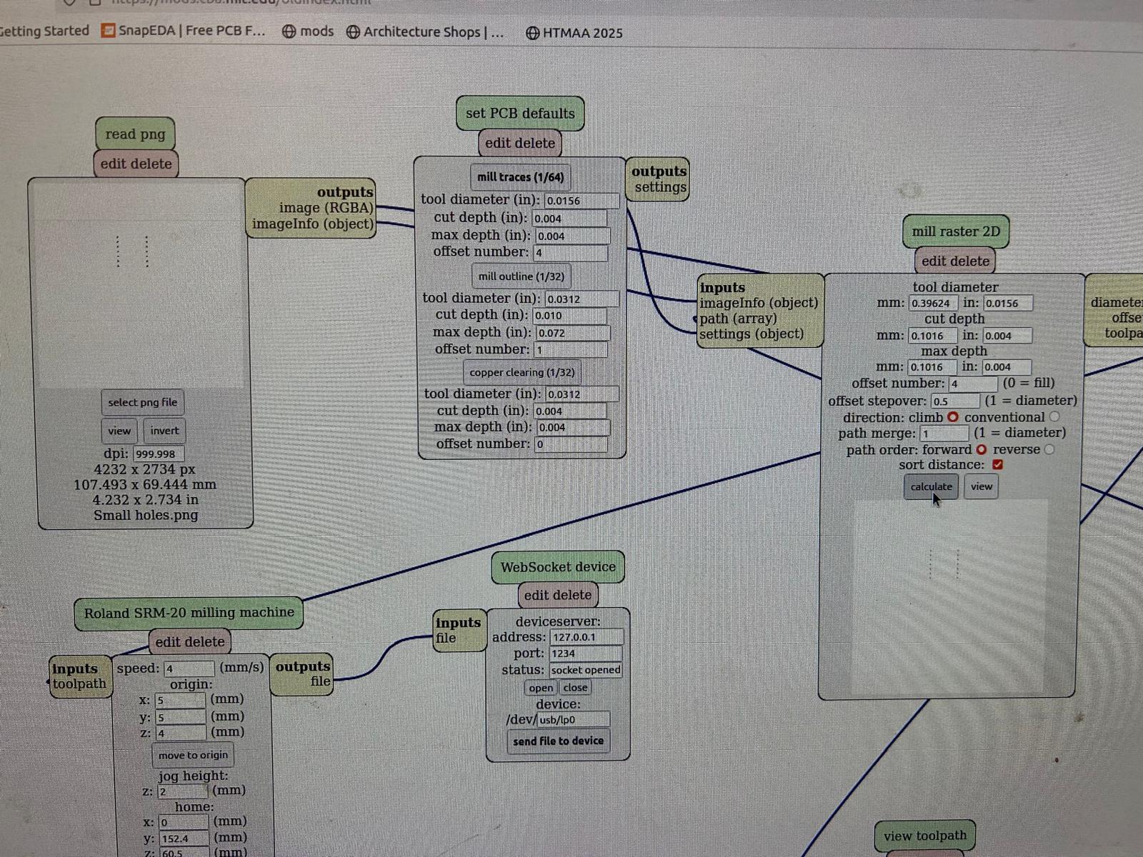
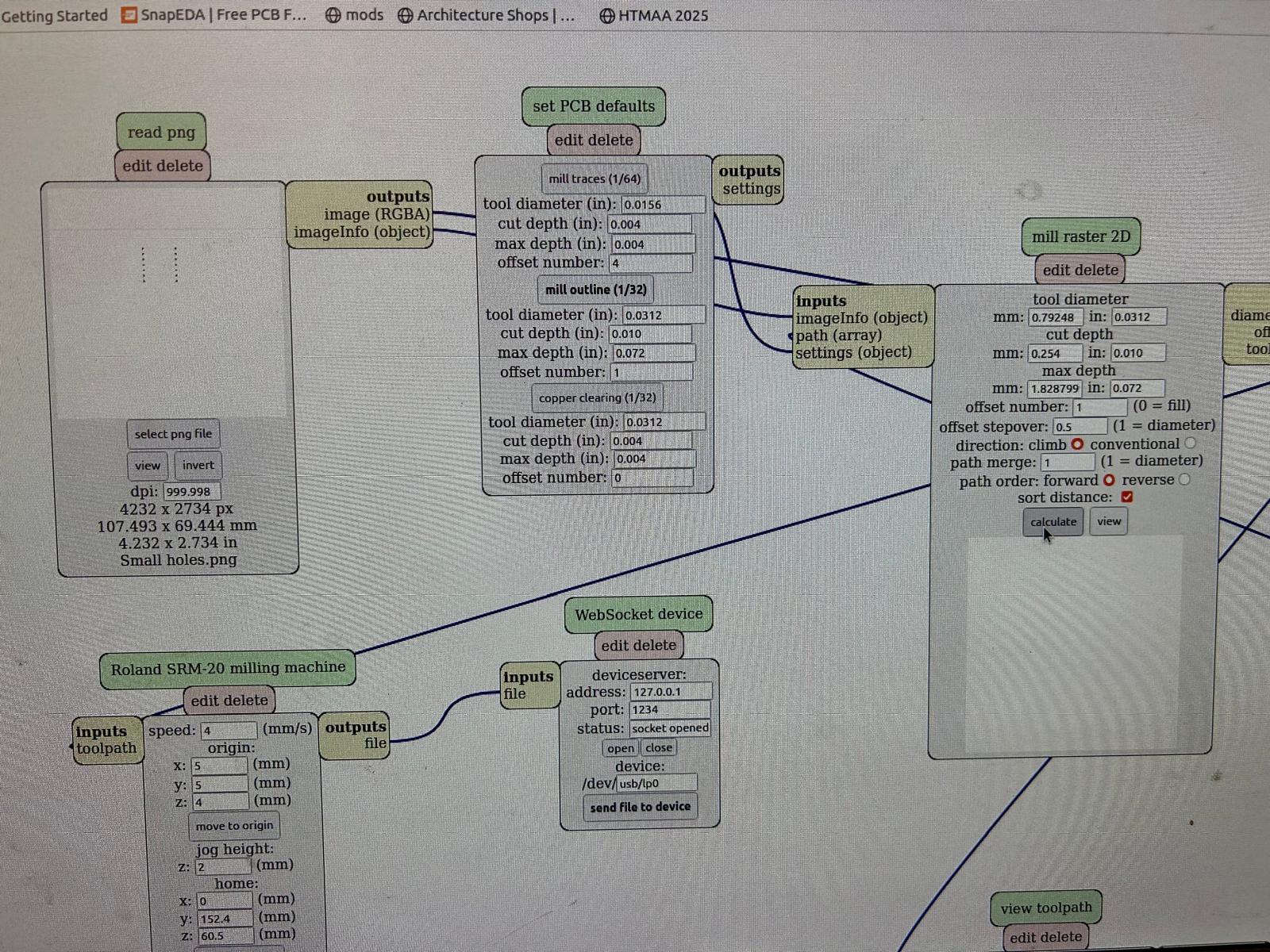
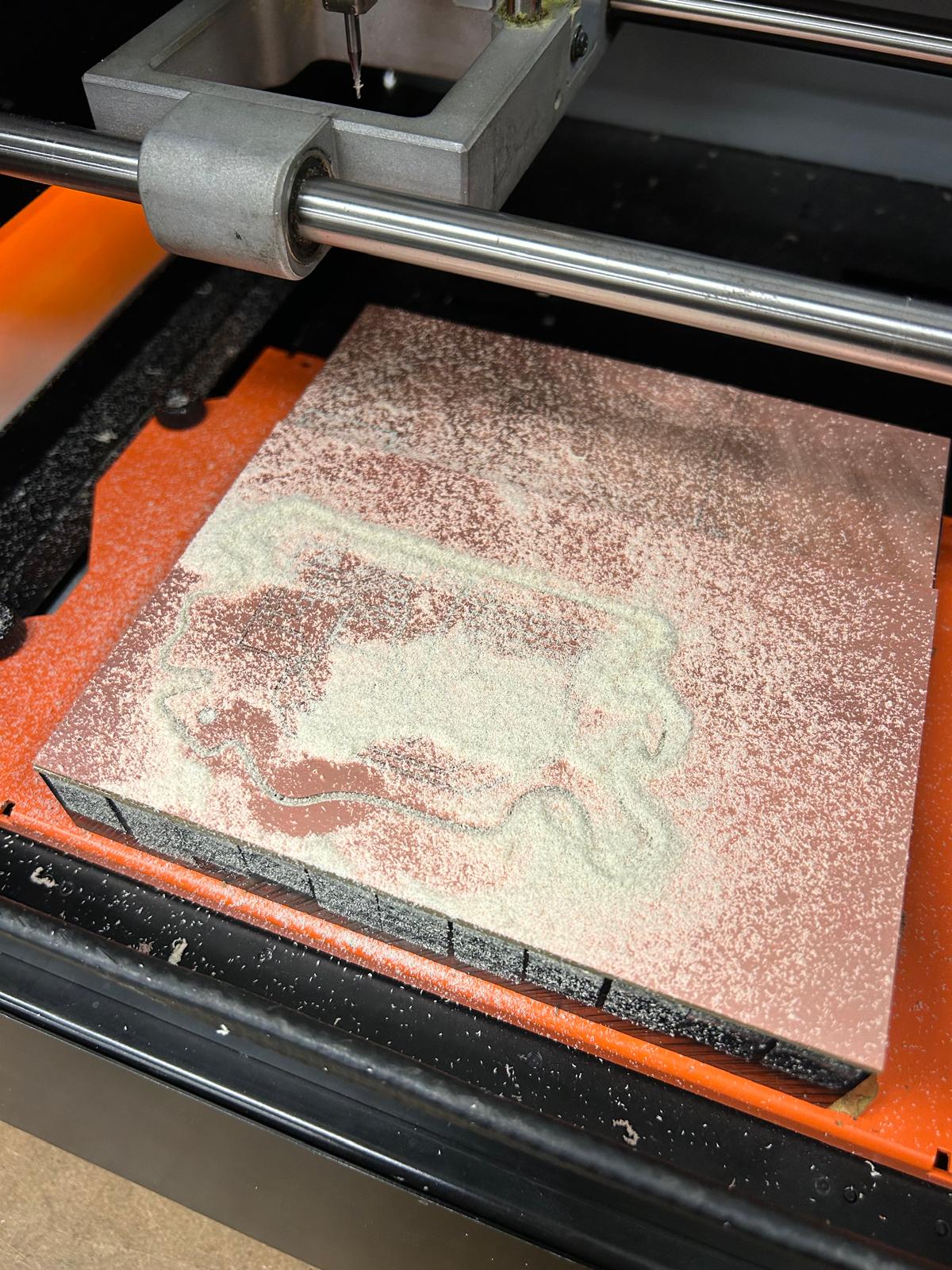
Following Jen's detailed recitation, I proceeded to mill my custom PCB using the Roland SRM-20 milling machine.
I began by preparing my design files, ensuring they were in the correct format and free of errors.


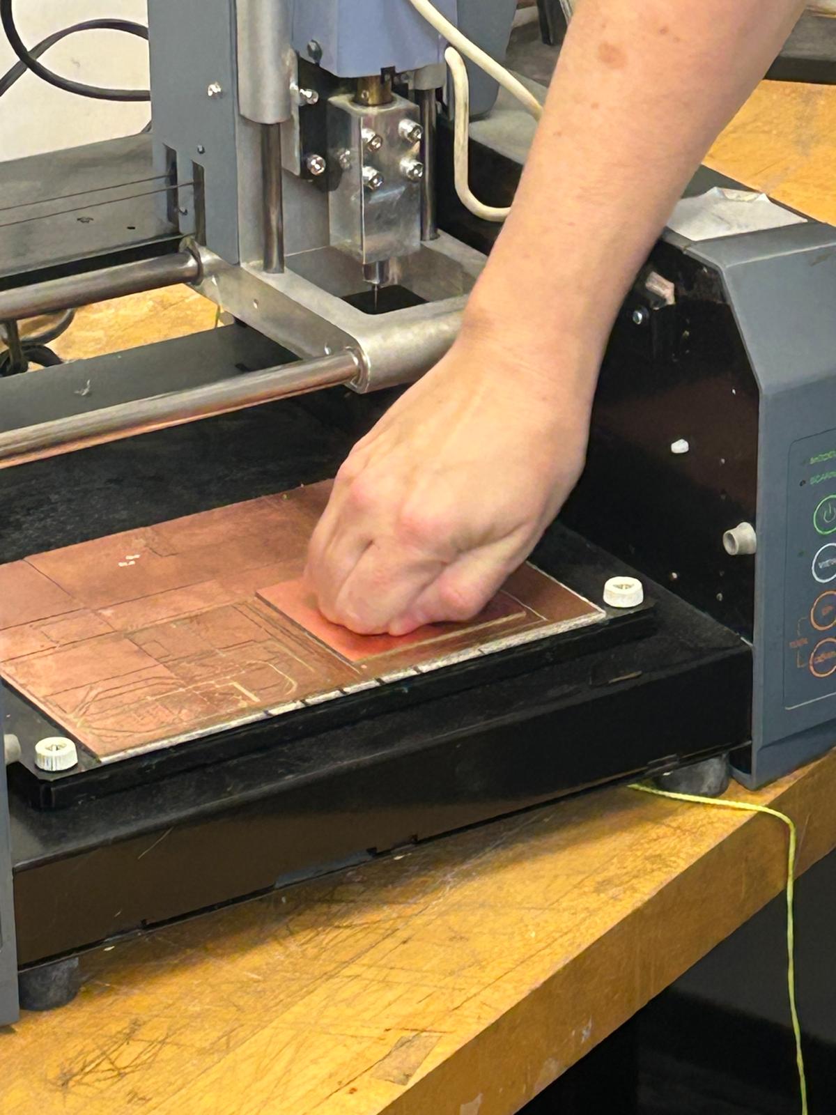
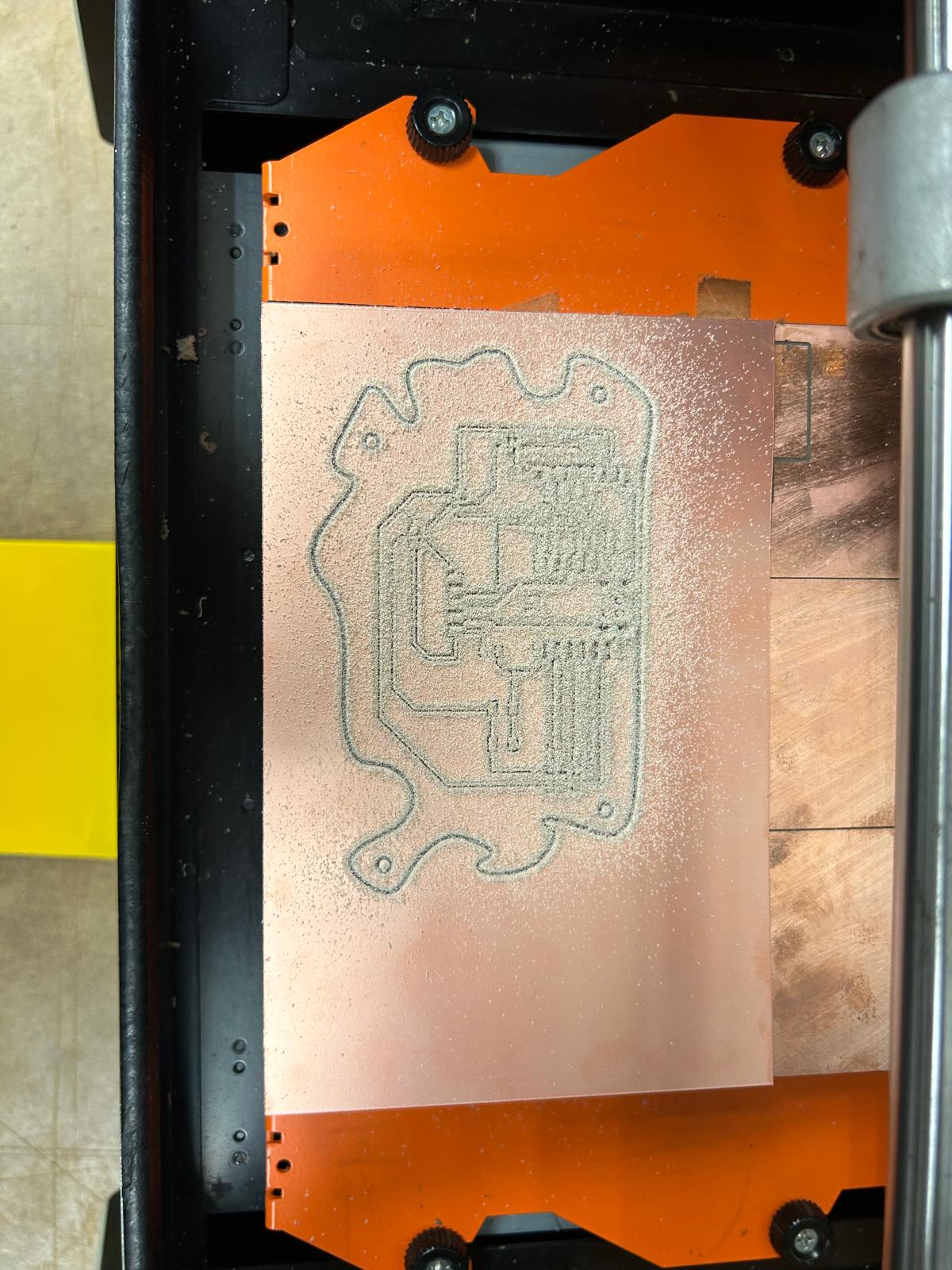
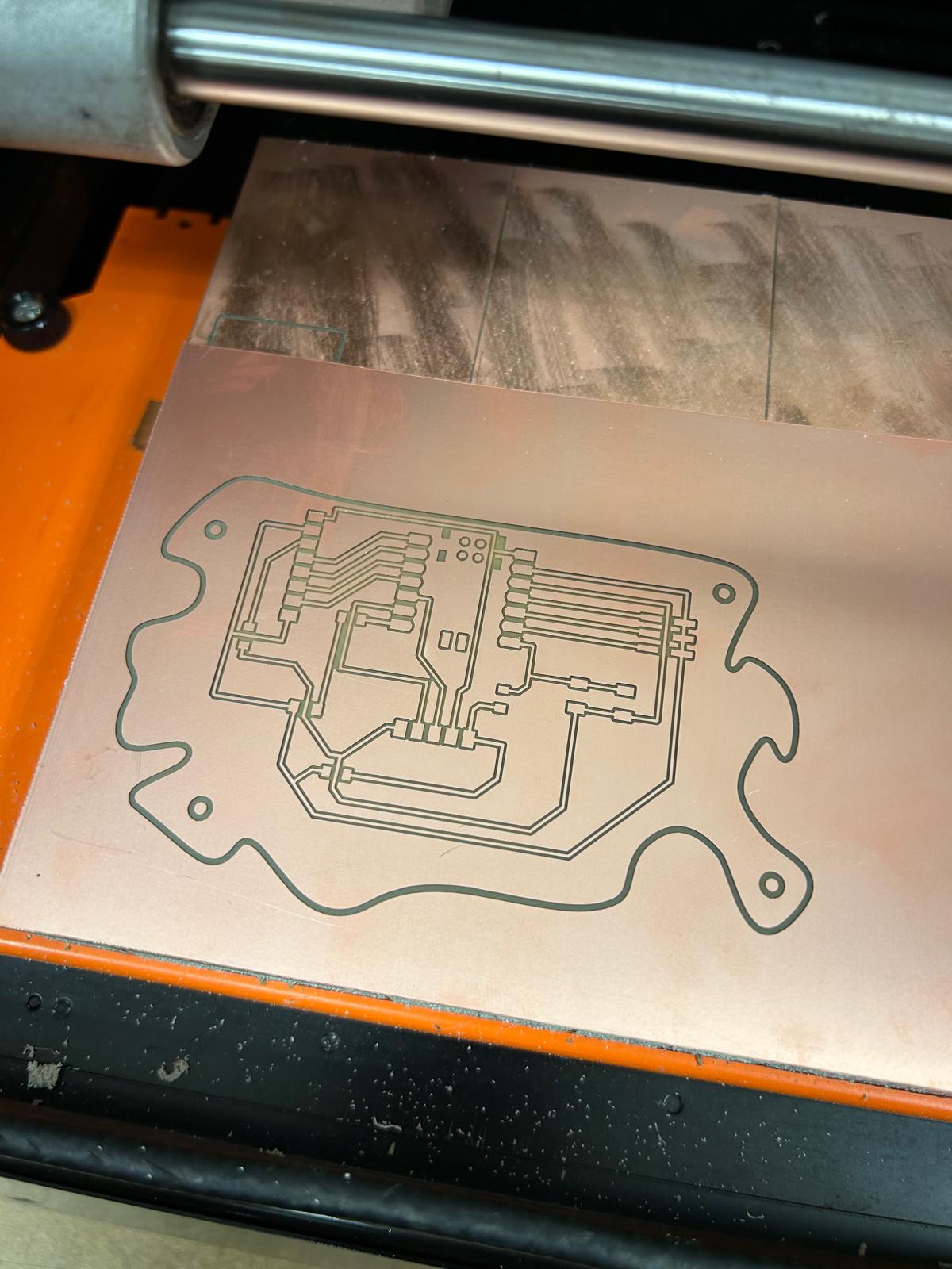
Milling my board
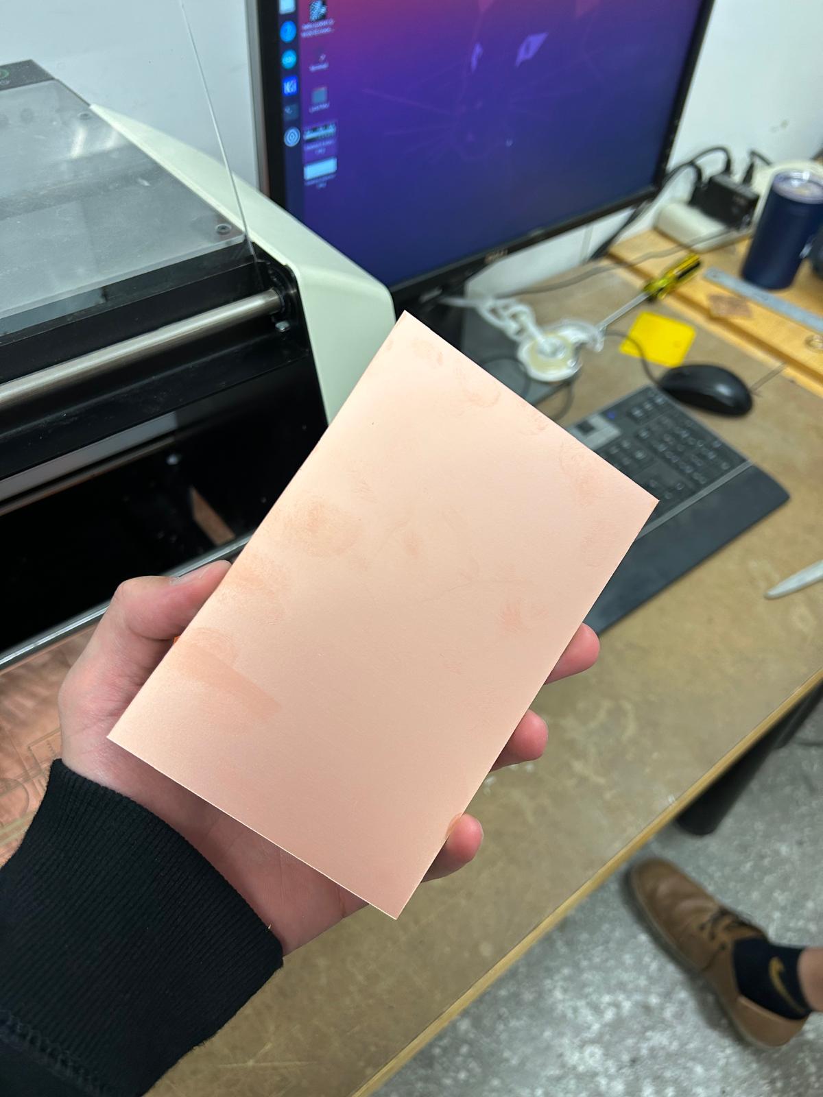
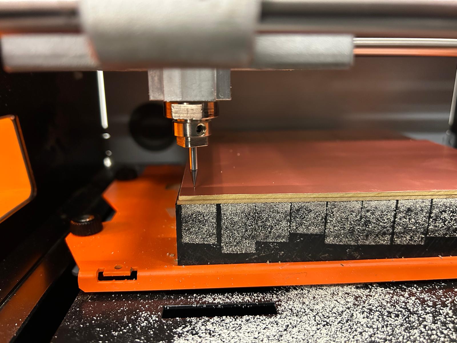
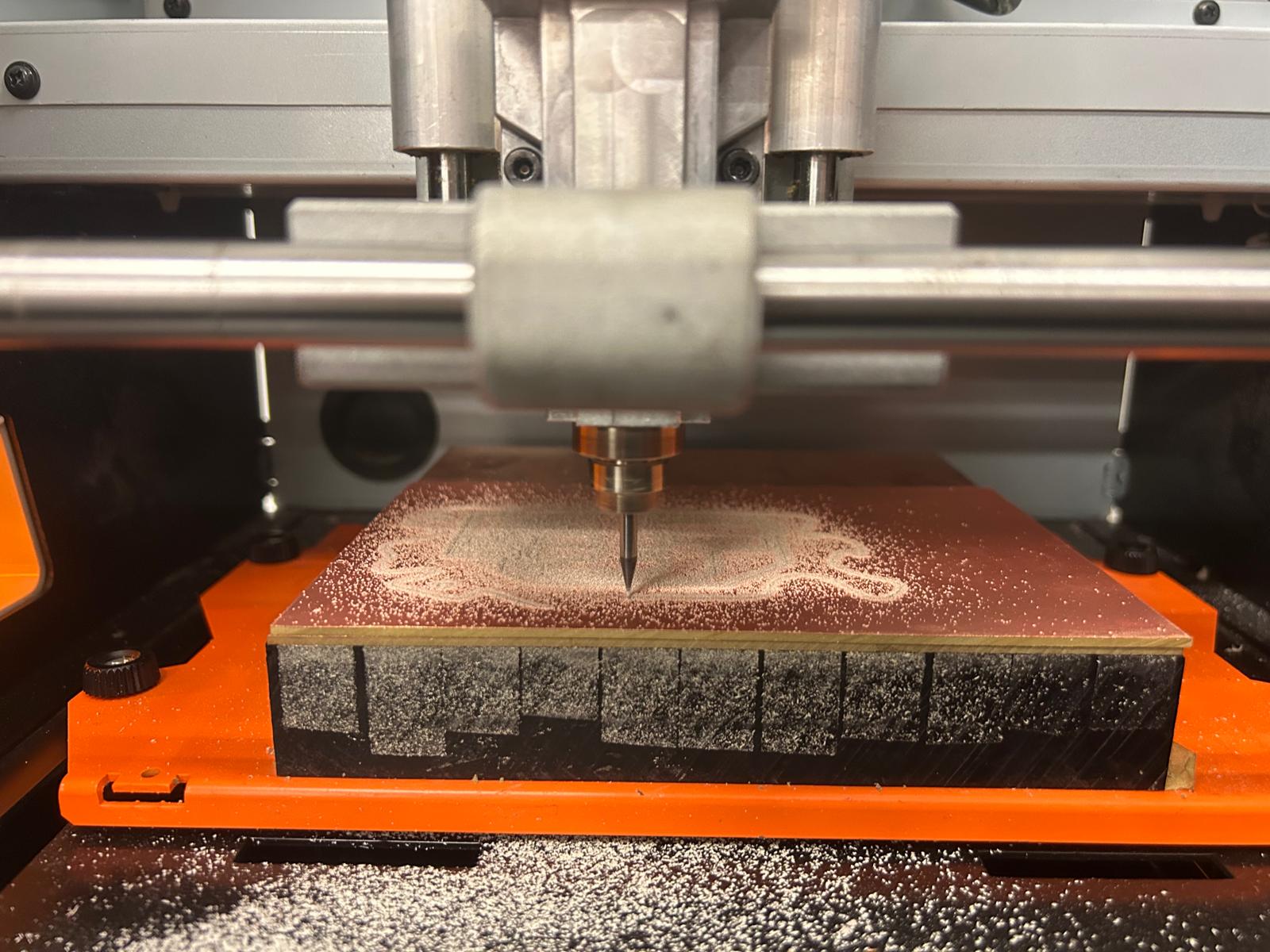
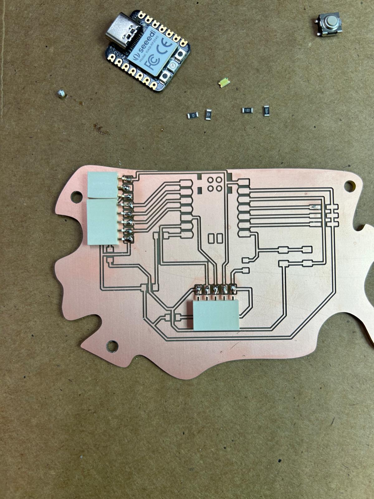
After selecting a suitable piece of copper-clad board, I securely mounted it onto the milling machine's bed using double-sided tape to prevent any movement during the milling process.
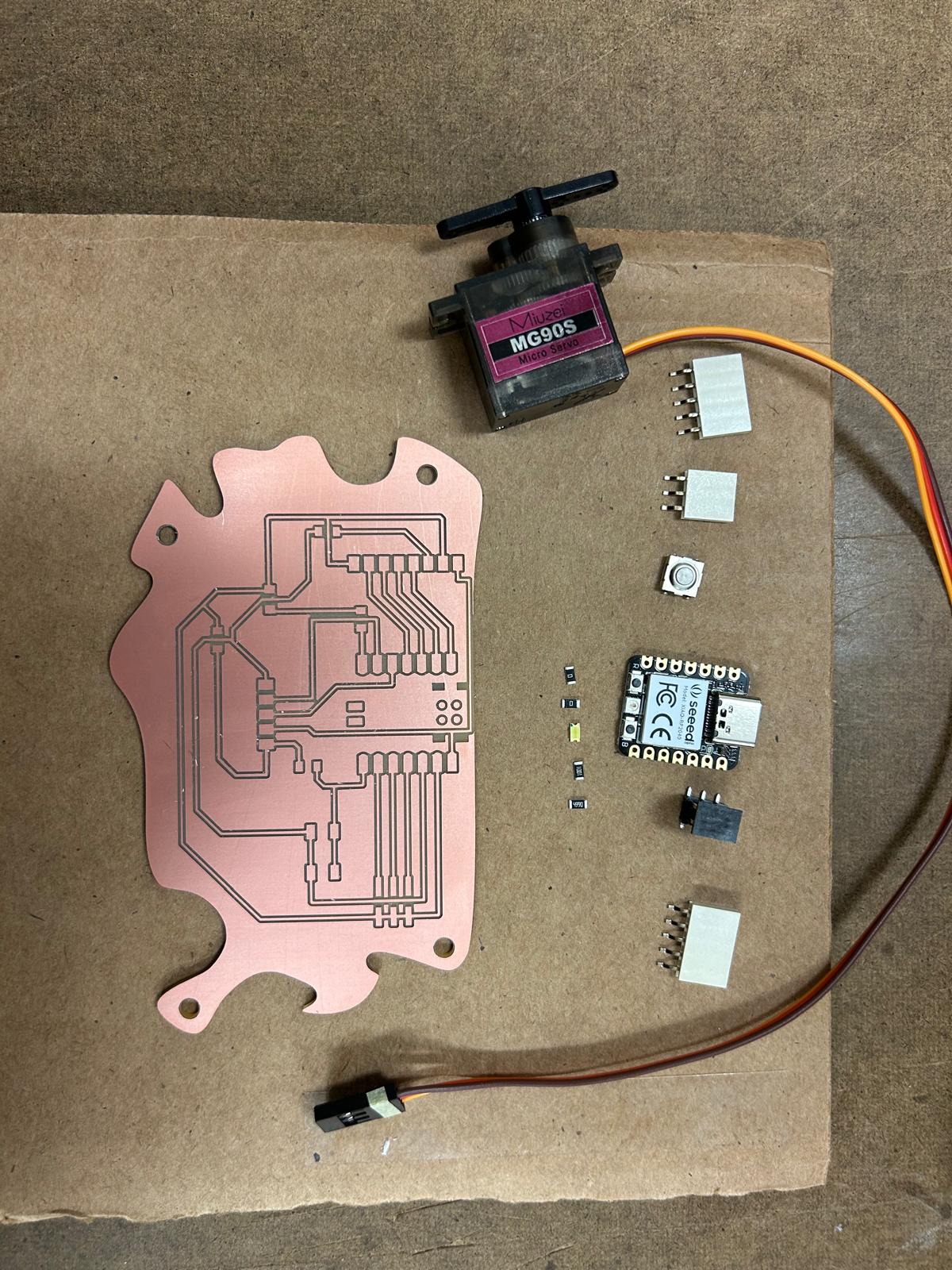
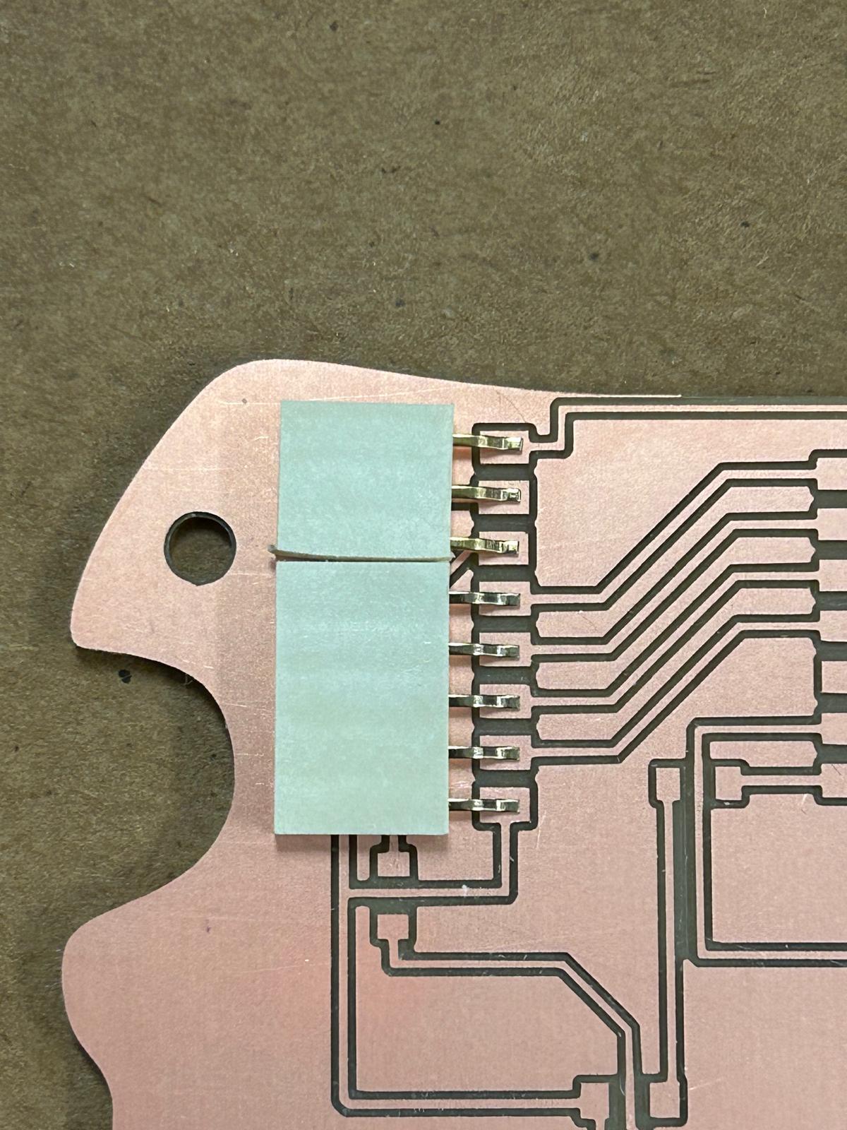
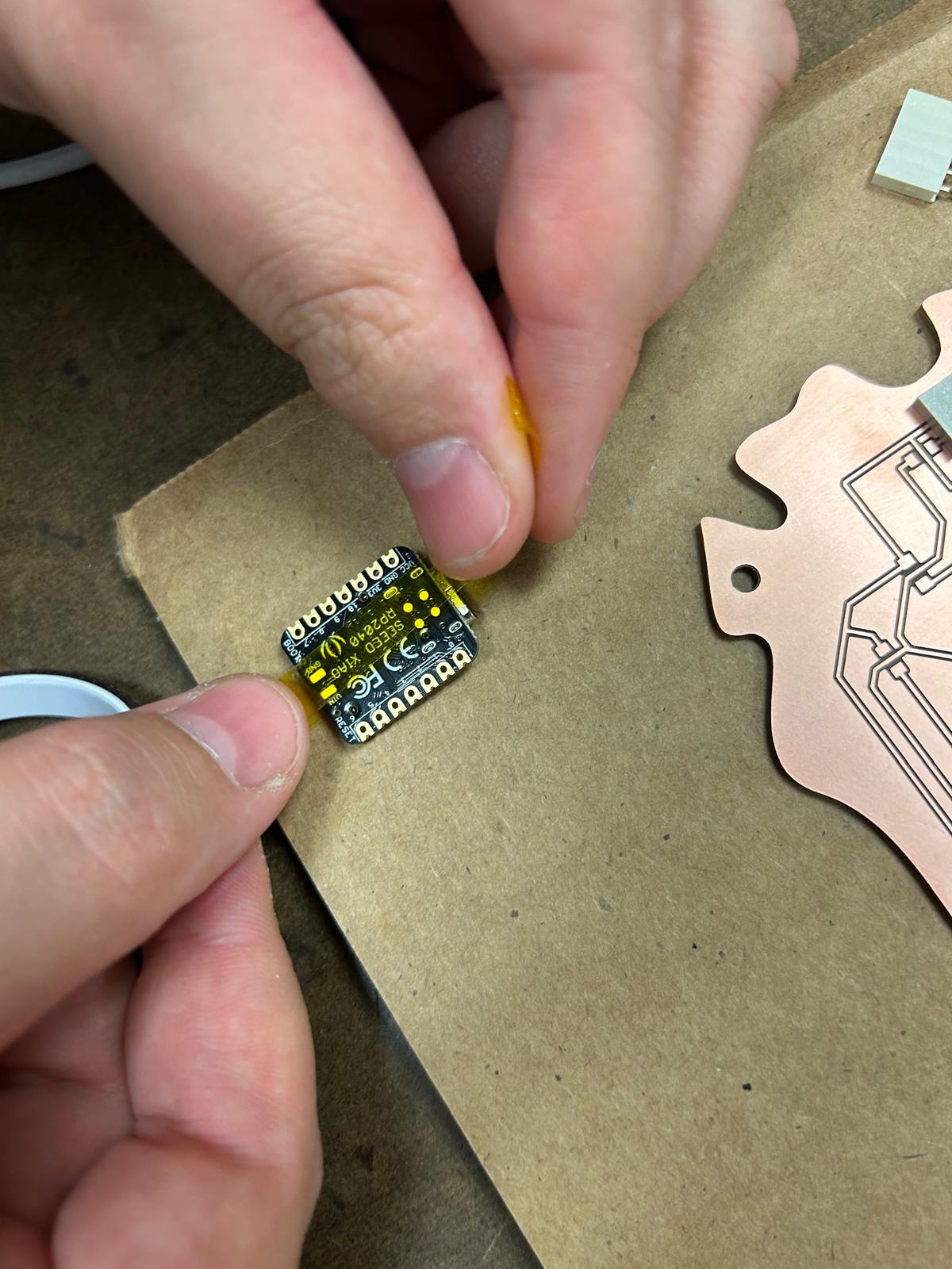
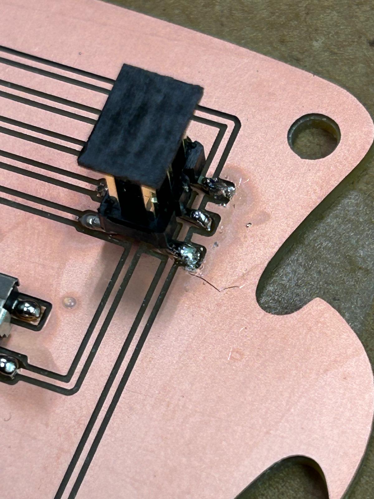
Soldering the components
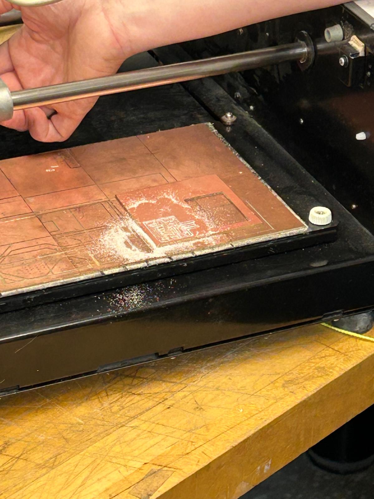
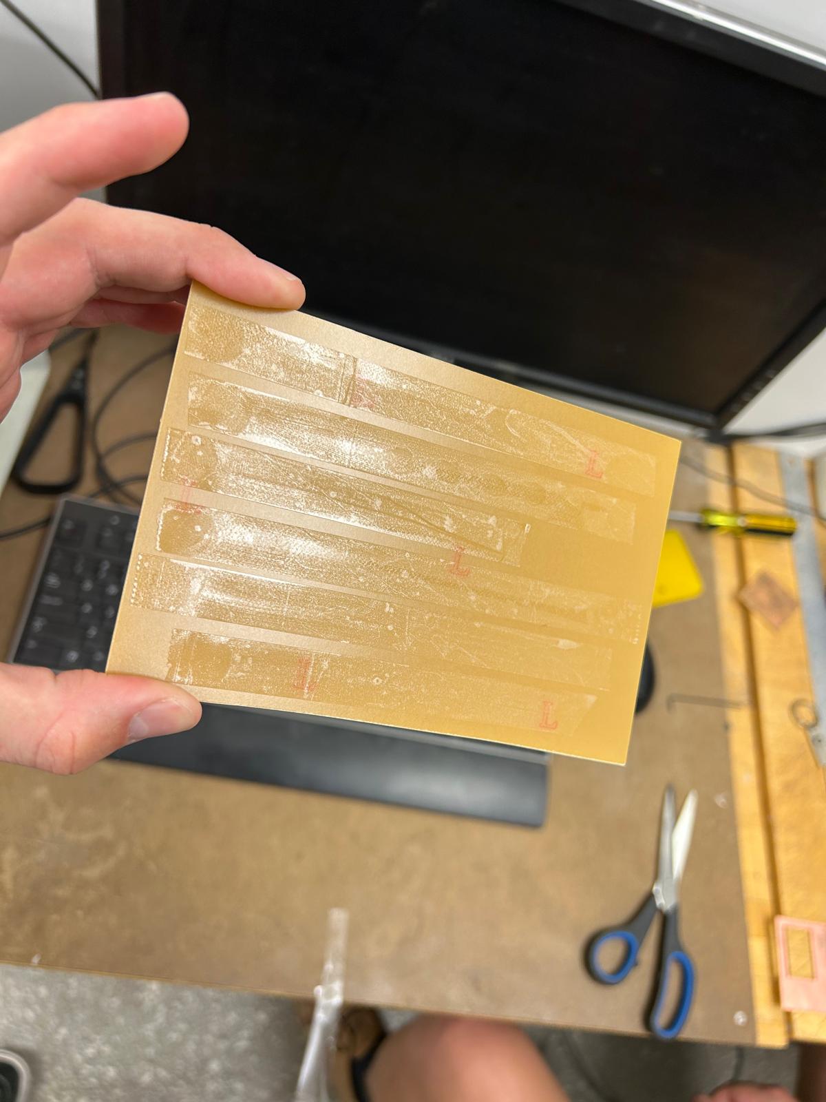
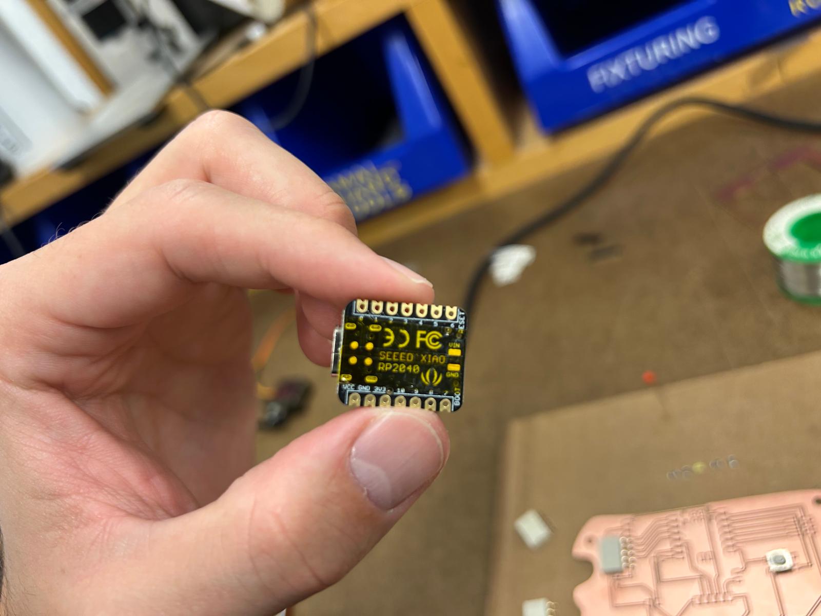
After successfully milling the PCB, I carefully removed it from the machine and inspected it for any defects or irregularities. Satisfied with the milling quality, I proceeded to solder the electronic components onto the board, following my design layout meticulously. I ensured that each component was correctly oriented and securely soldered to establish reliable electrical connections. Once all components were in place, I conducted a thorough inspection to verify that there were no solder bridges or cold joints that could compromise the functionality of the circuit.
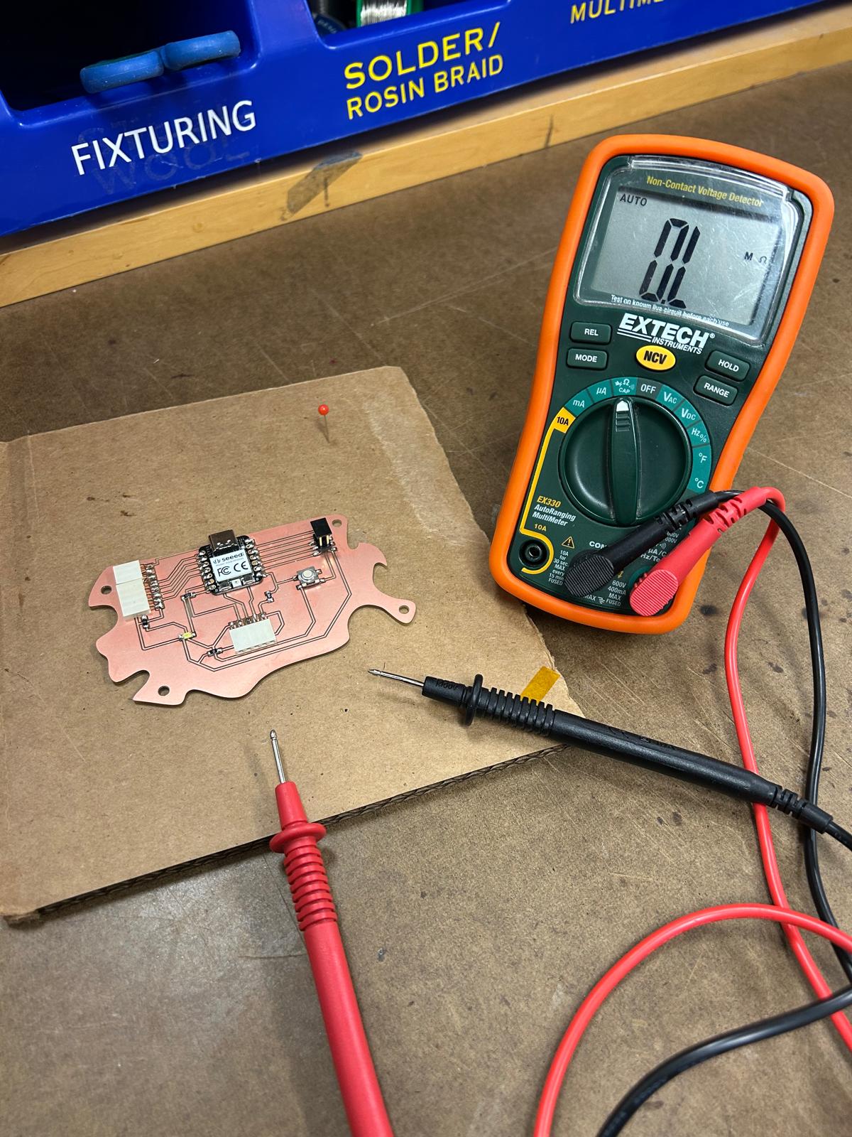
Using the multimeter to check my circuit
After completing the soldering process, I utilized a multimeter to test the continuity and functionality of my circuit. I checked each connection point to ensure that there were no open circuits or short circuits that could affect the performance of the board. By measuring the voltage levels at various points in the circuit, I confirmed that all components were receiving the correct power supply and that the circuit was operating as intended. This step was crucial in verifying the integrity of my design and ensuring that my PCB was ready for deployment in its intended application.
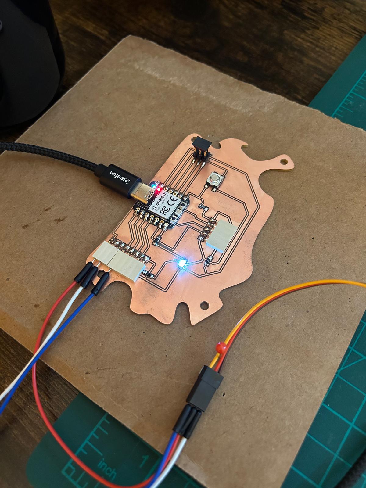
Programming my board
After verifying the integrity of my soldered PCB using a multimeter, I proceeded to program the microcontroller on the board. I connected the PCB to my computer using a USB cable and opened the appropriate Integrated Development Environment (IDE) for coding. I wrote a simple program to test the functionality of the board, ensuring that all components were responding correctly. After uploading the code to the microcontroller, I monitored the board's performance to confirm that it was executing the program as expected. This step was essential in validating that my design and assembly were successful, and that the PCB was fully operational.
Code for the led to work void setup() { pinMode(D6, OUTPUT); // Set the LED pin as an output digitalWrite(D6, HIGH); // Turn the LED on } void loop() { }
#include


Servo myservo;  // create servo object to control a servo
// twelve servo objects can be created on most boards


void setup() {
 myservo.attach(26);  // attaches the servo on GIO26 to the servo object
}


void loop() {
 int pos;


 for (pos = 0; pos <= 180; pos += 1) { // goes from 0 degrees to 180 degrees
   // in steps of 1 degree
   myservo.write(pos);              // tell servo to go to position in variable 'pos'
   delay(15);                       // waits 15ms for the servo to reach the position
 }
 for (pos = 180; pos >= 0; pos -= 1) { // goes from 180 degrees to 0 degrees
   myservo.write(pos);              // tell servo to go to position in variable 'pos'
   delay(15);                       // waits 15ms for the servo to reach the position
 }