* First tests showed unexpected alignment — revisit measurements.
* The middle image needs improved contrast for documentation clarity.
* Final version complete — update image with printed result.

week 7:computer-controlled machining

woodshop training

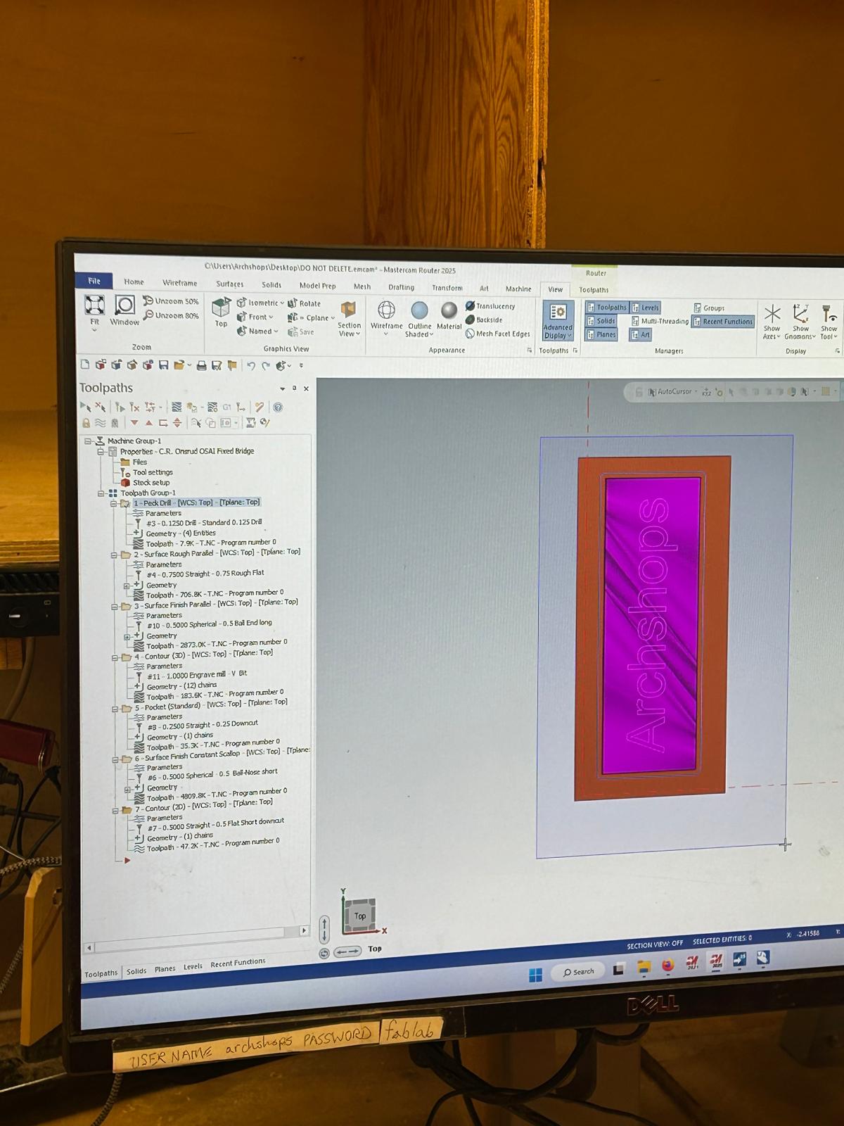
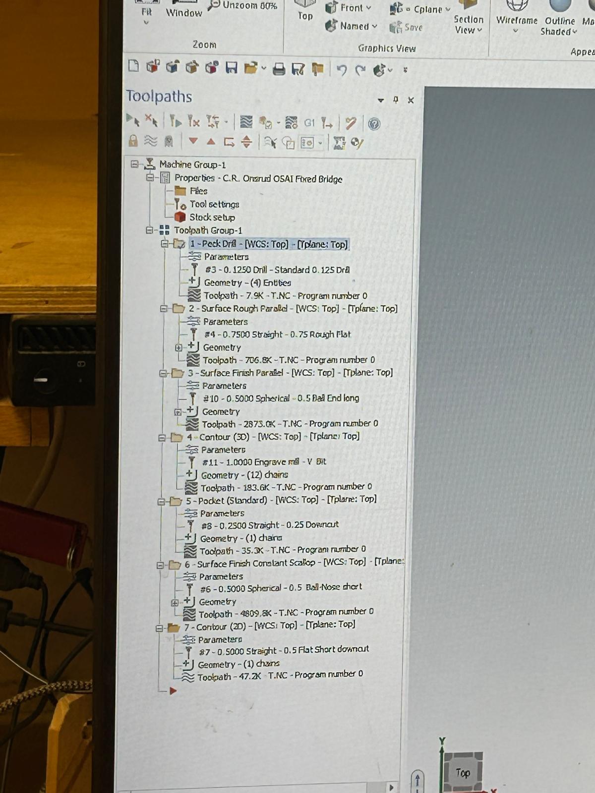
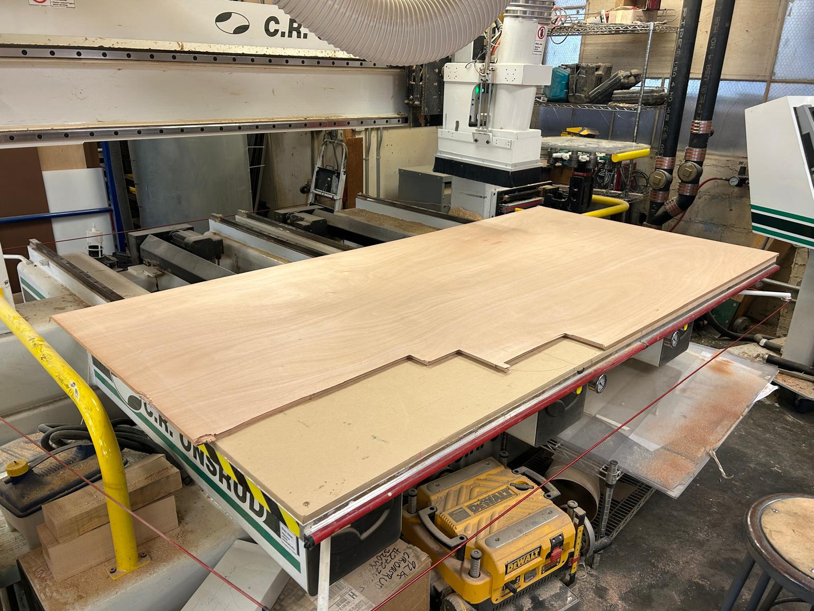
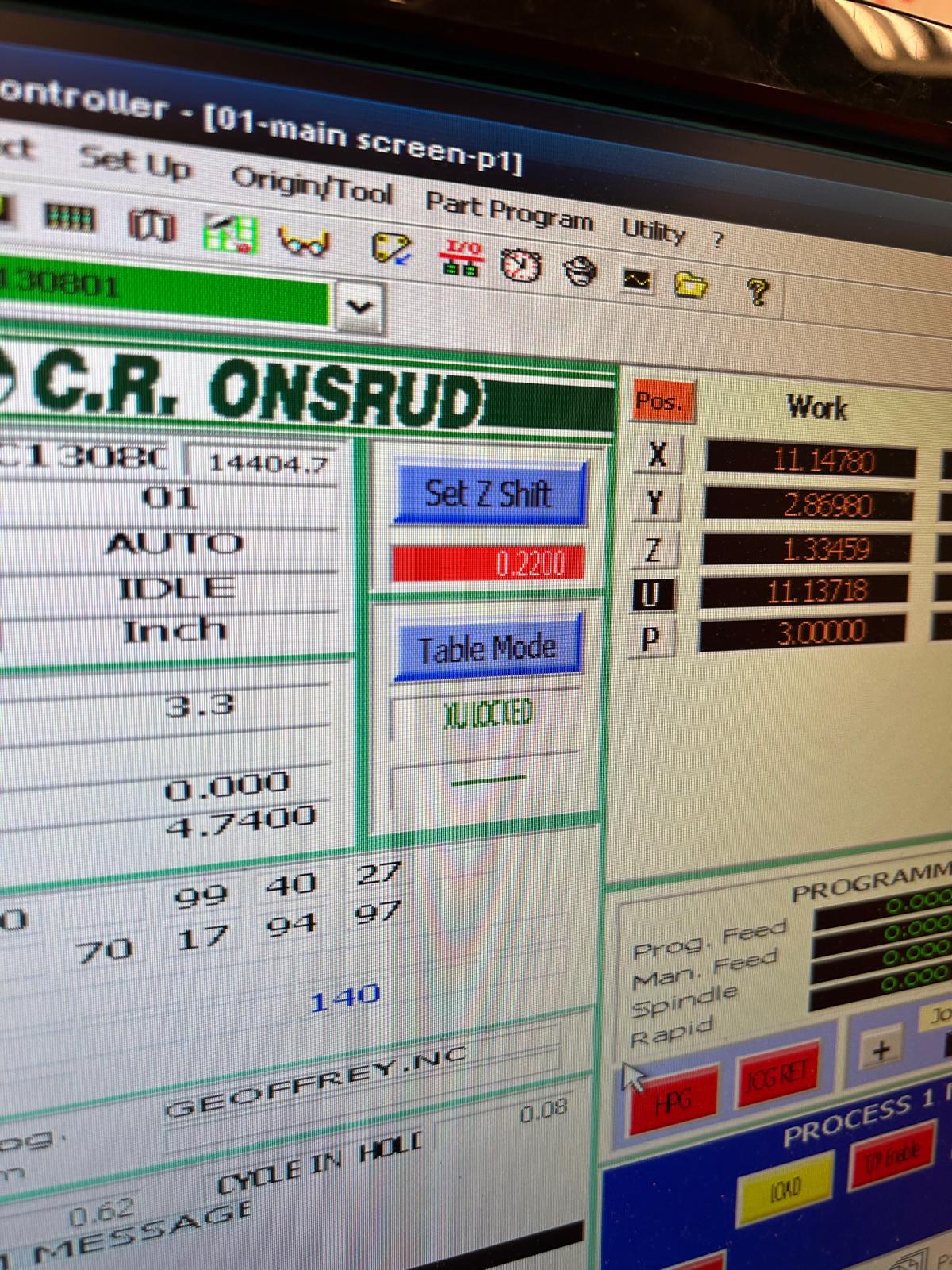
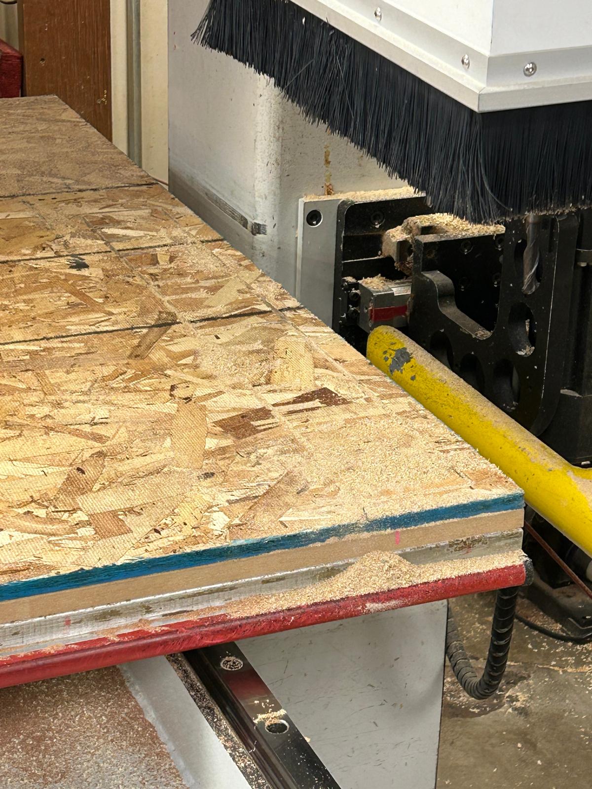
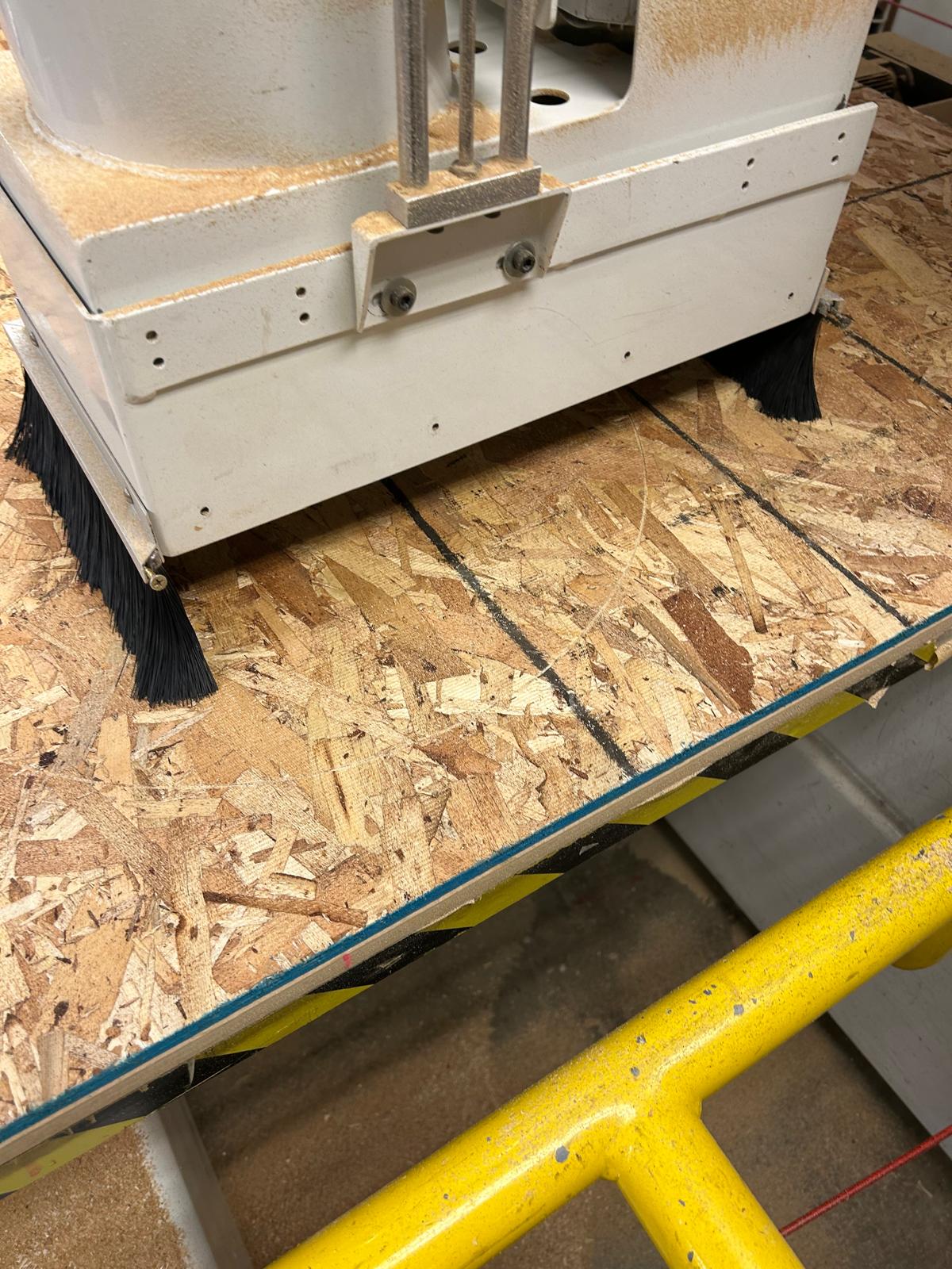
This week started with Chris’s training session at the woodshop. When I arrived, Carlos was already there, working on his project using plywood. Chris explained the main differences between OSB (Oriented Strand Board) and plywood, and in which cases each material is more appropriate. After that, he gave us a short introduction to preparing toolpaths in Mastercam, and once our files were ready, we were set to import the G-code into the Onsrud CNC router. We ran a test cuts using both materials and found that a 0.46-inch toolpath width worked best for the 0.433-inch OSB board.

7.1
Chris started explaining how the software works
7.2
setting up the parameters and the mill
7.3
testing the plywood that Carlos was about to use
7.4
checking the result of the test
7.5
it was really hard to remove the pieces from the stock and as a result some of the parts were damaged
7.6
we measured the thickness of the stock so that we can correctly calculate the size of the joints
7.7
some of Chris’s notes
7.8
this specific onsrud machine at n51 needs the Z shift to be 0.22in
7.9
we were watching carefully the machine to be sure that everything works properly and avoid any accidents
7.10
the pieces are ready to test
7.11
first we had to clean some of the rough edges
7.12
we tested all the possible combinations
7.13
me and my group decided that the best fit for 0.433in thickness was the 0.46in gap

Project Development

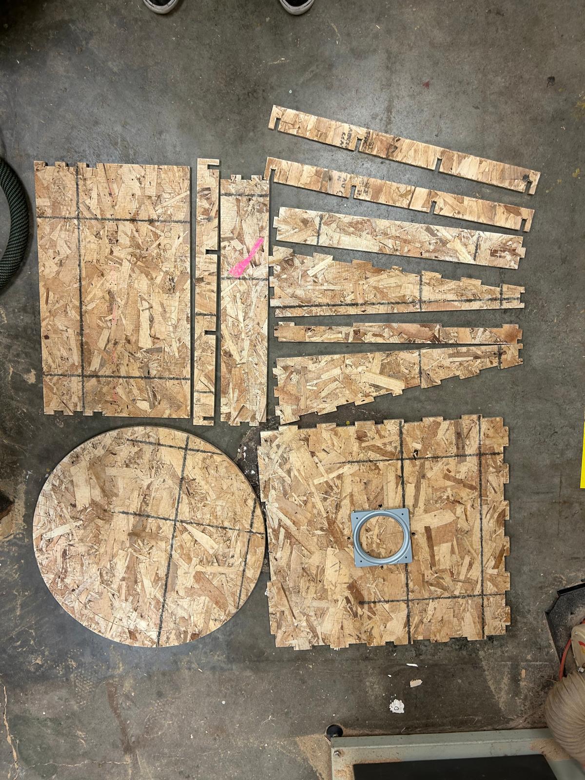
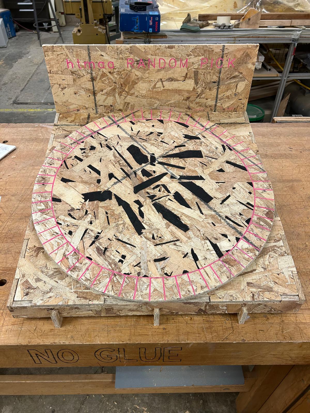
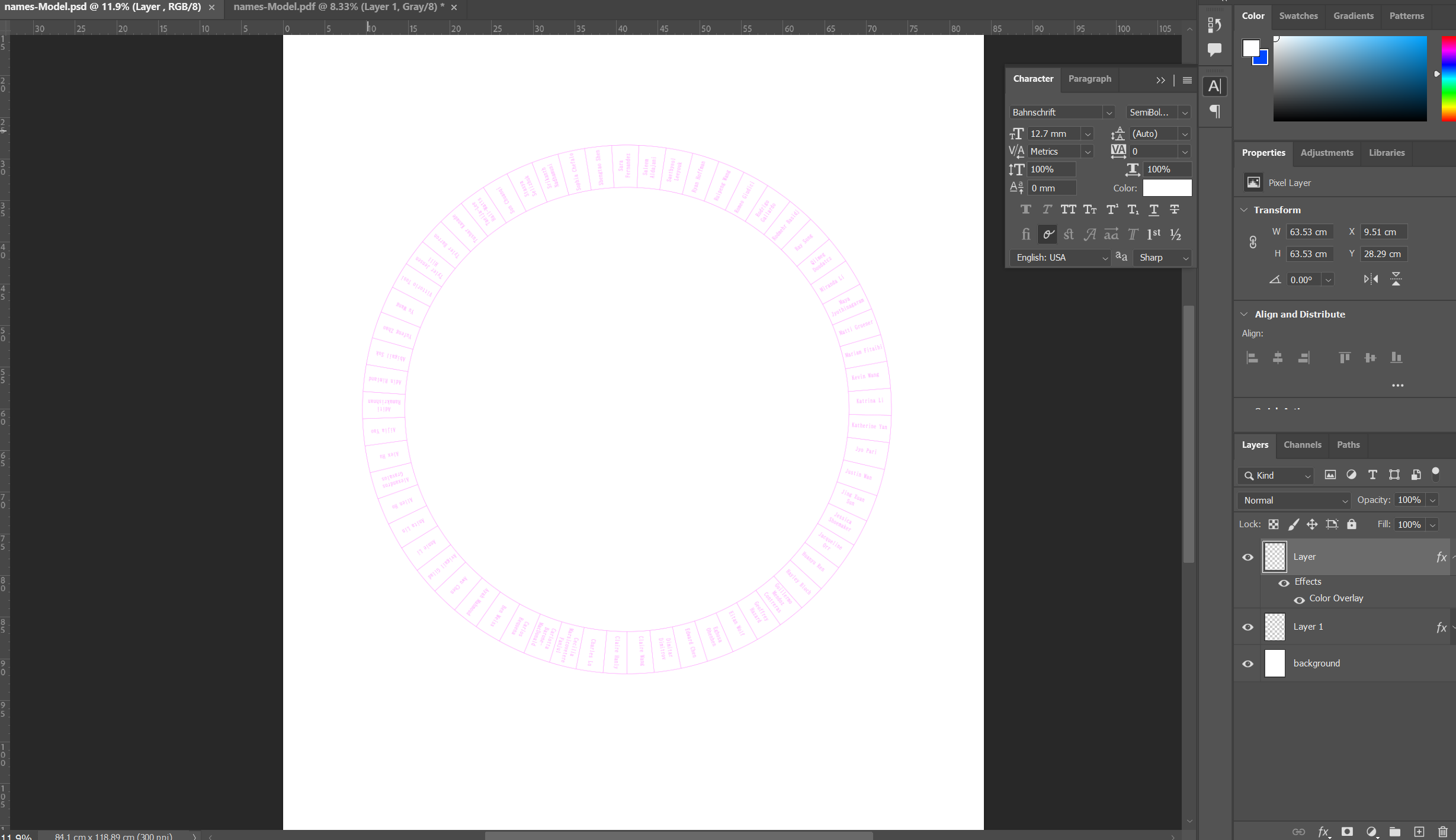
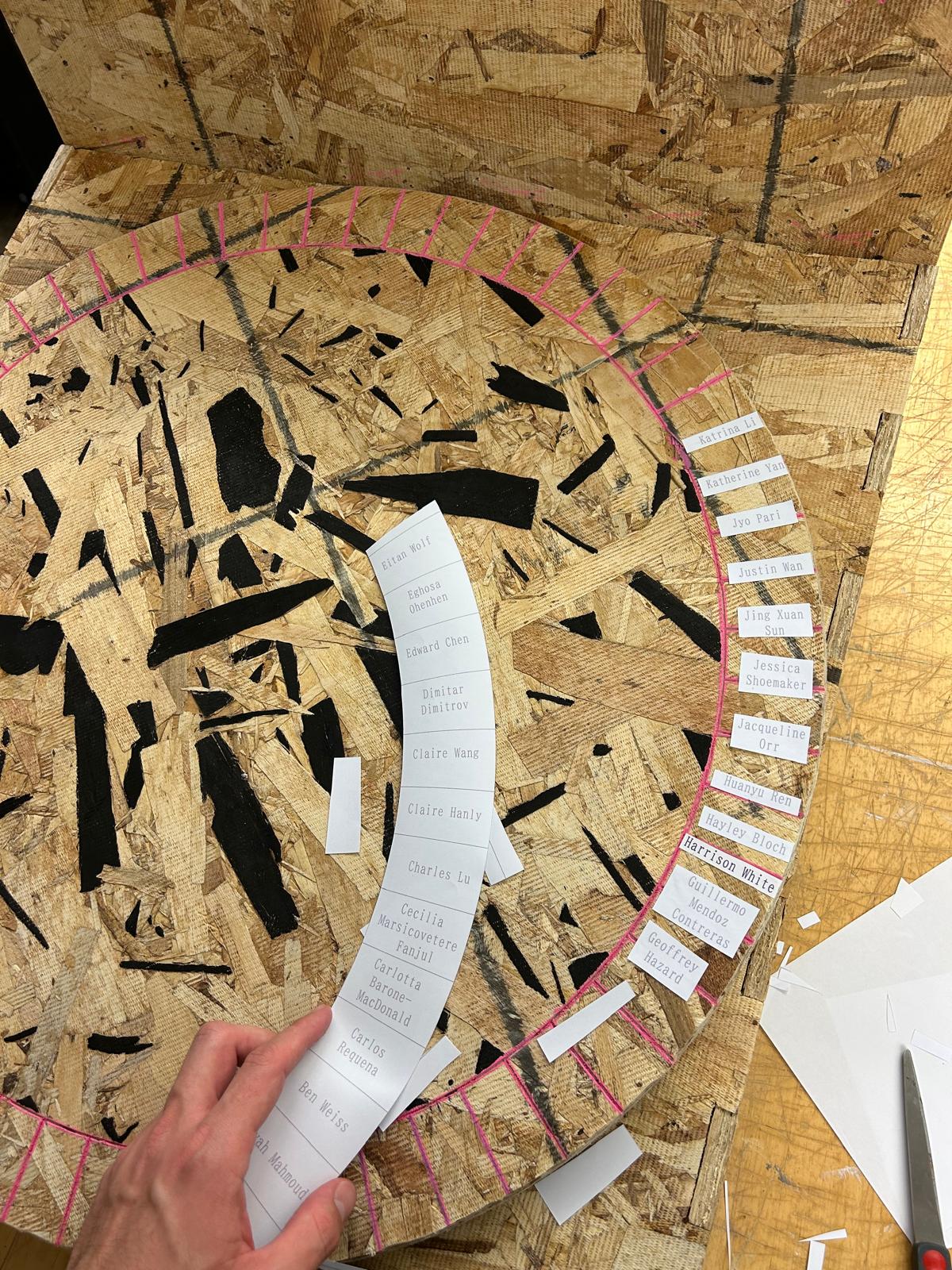
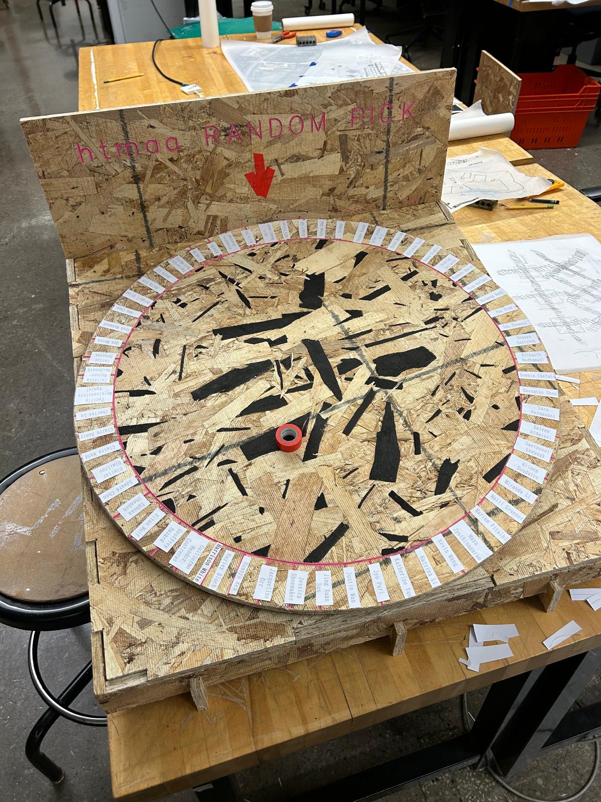
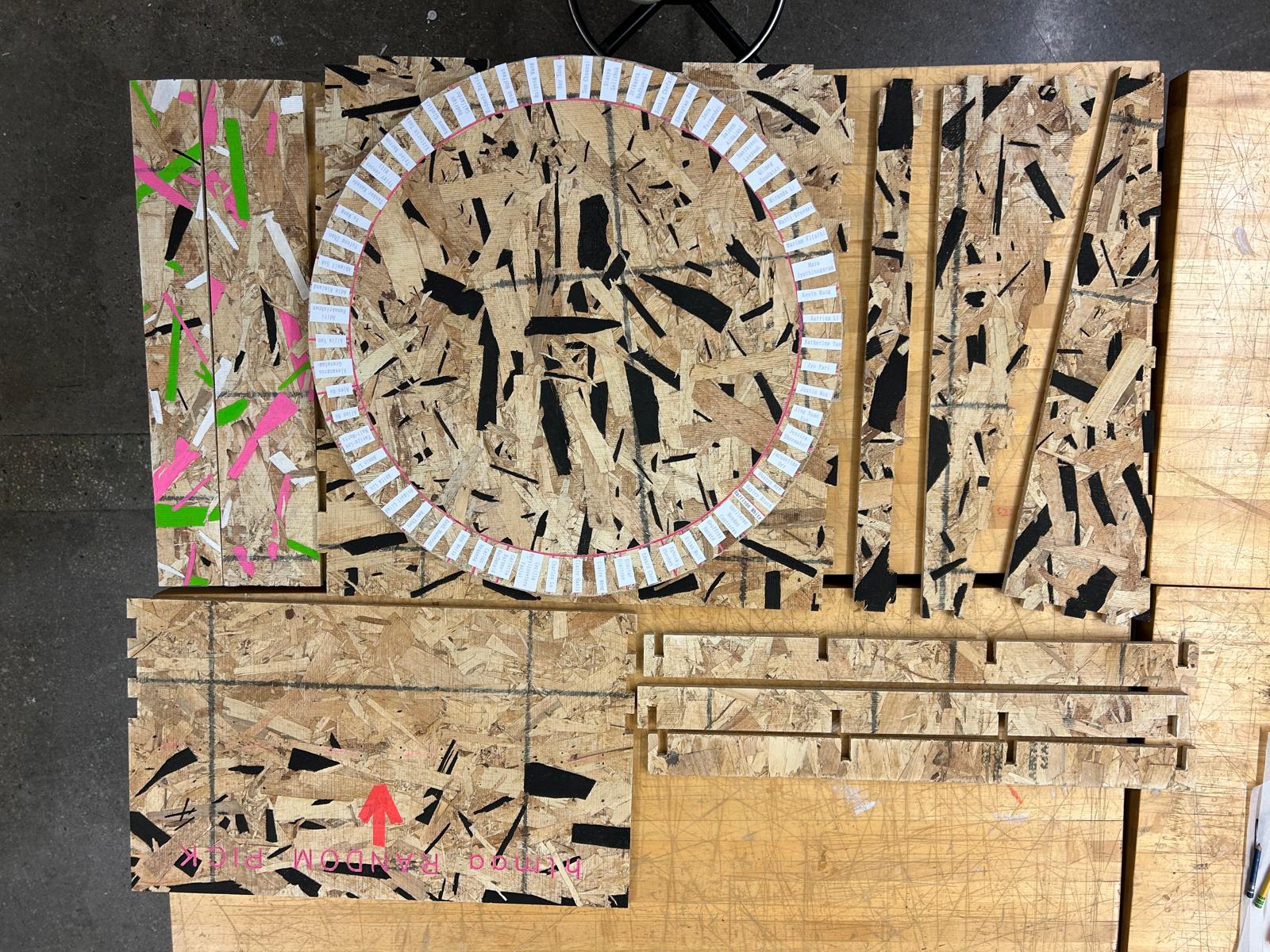
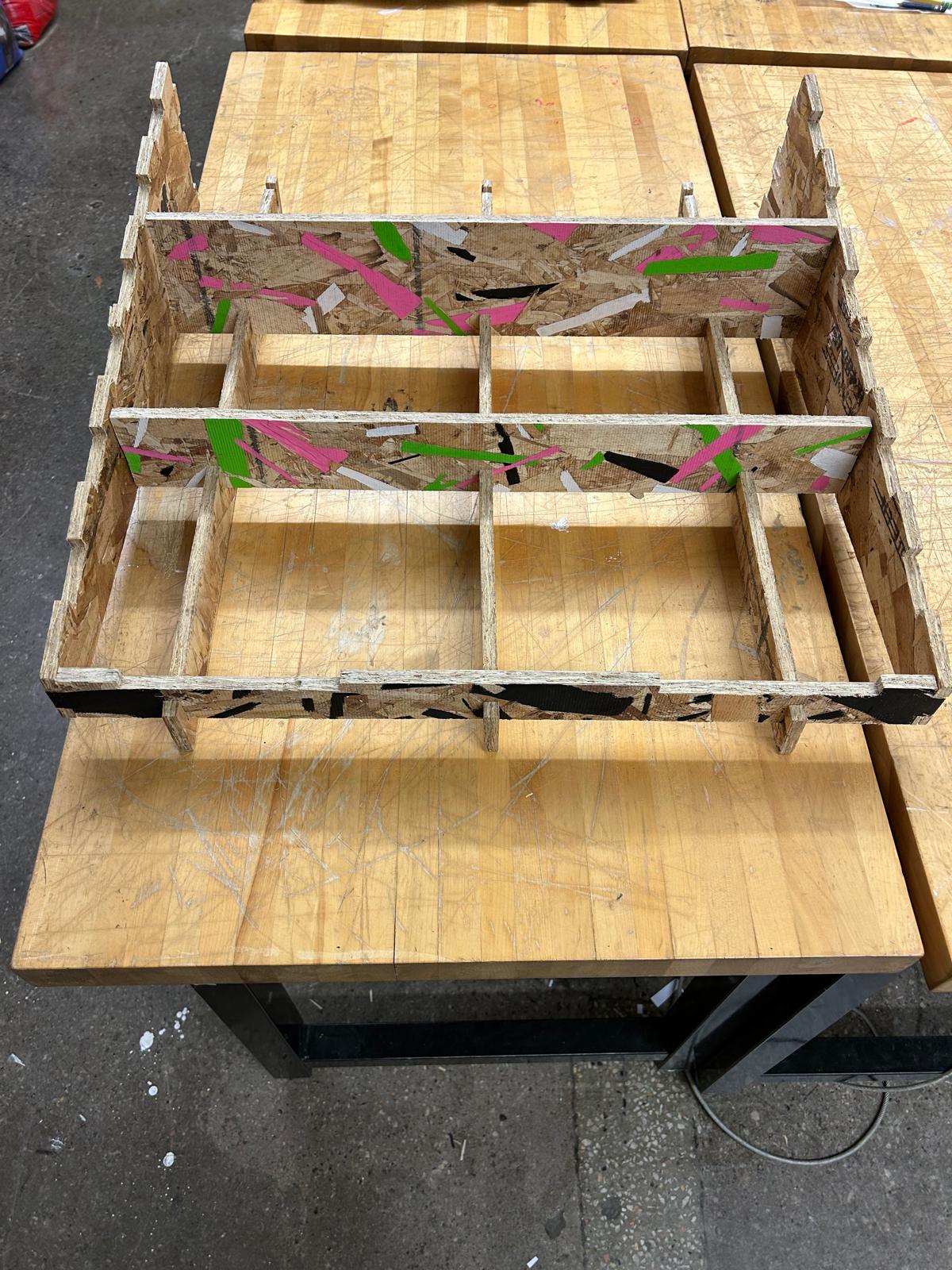
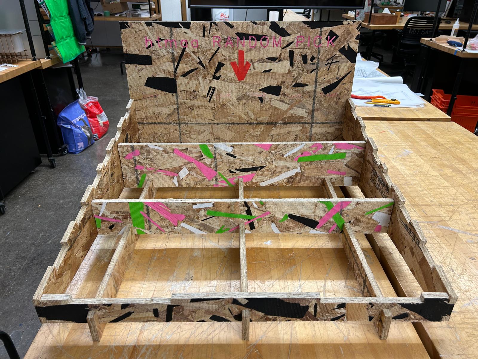
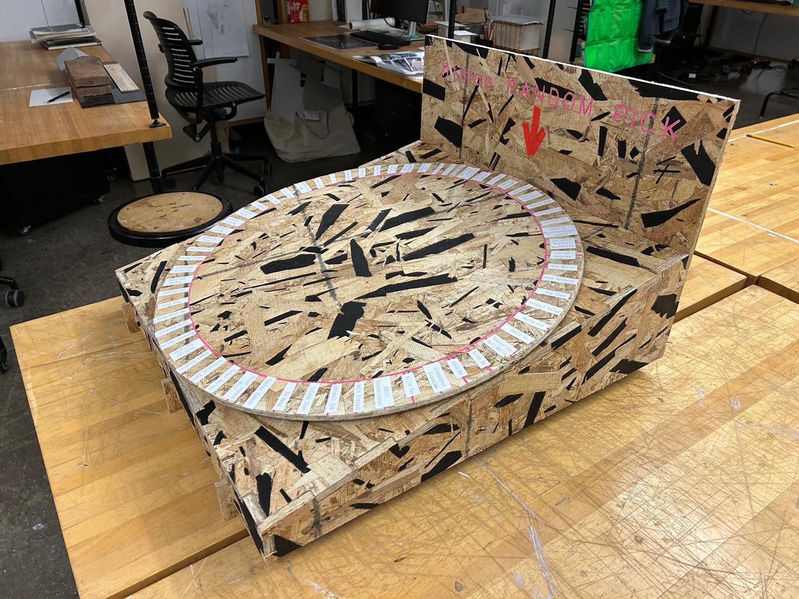
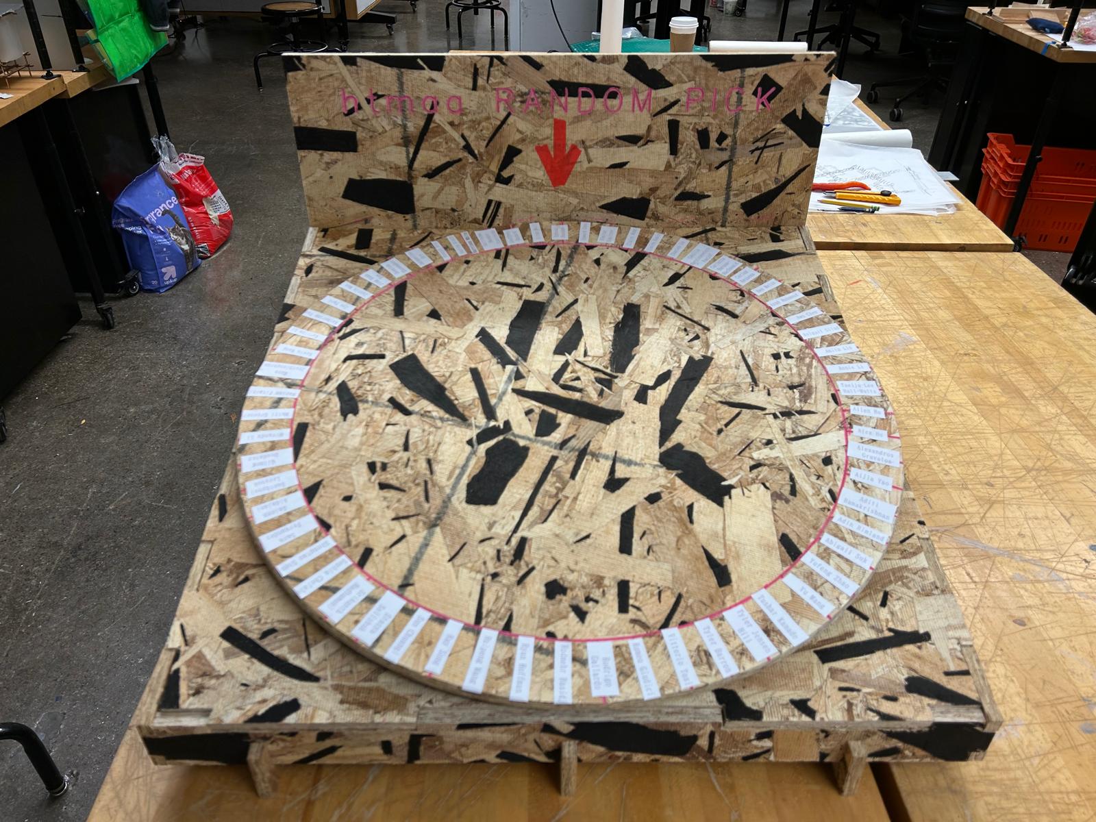
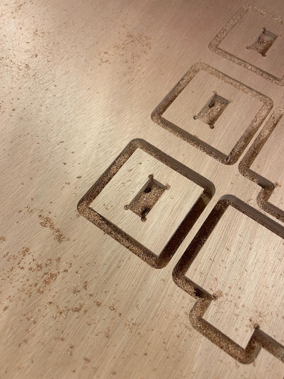
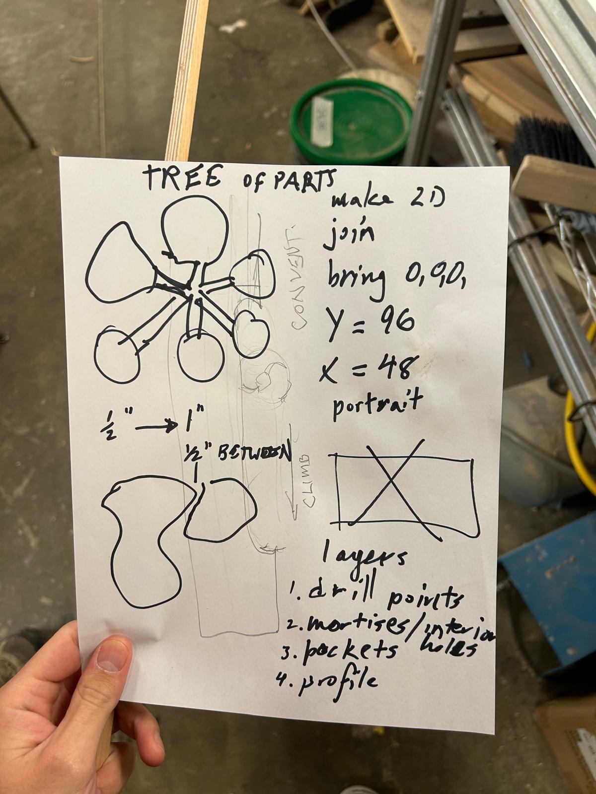
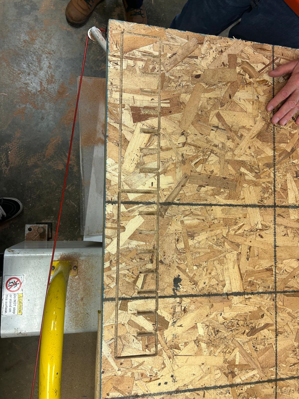
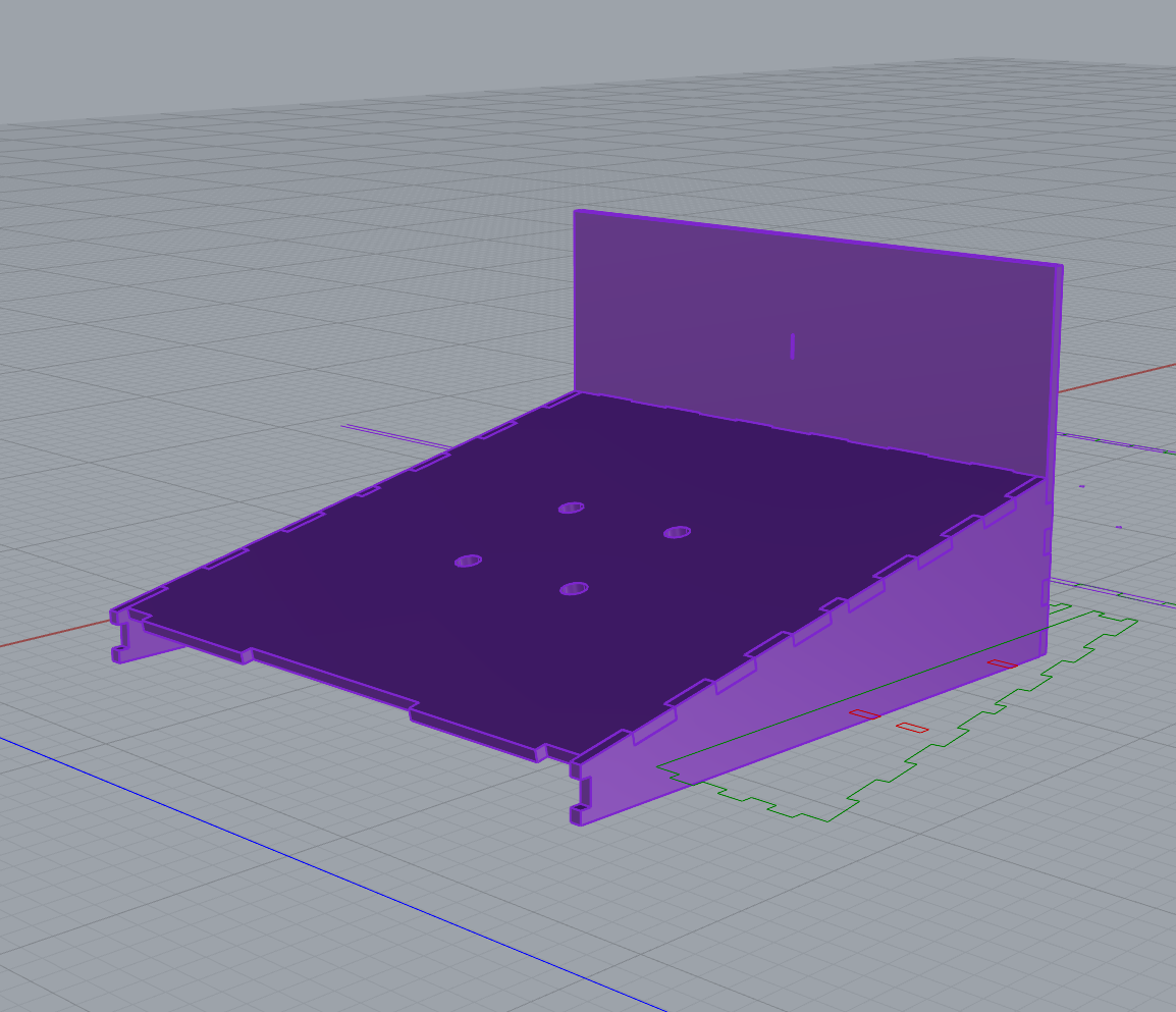
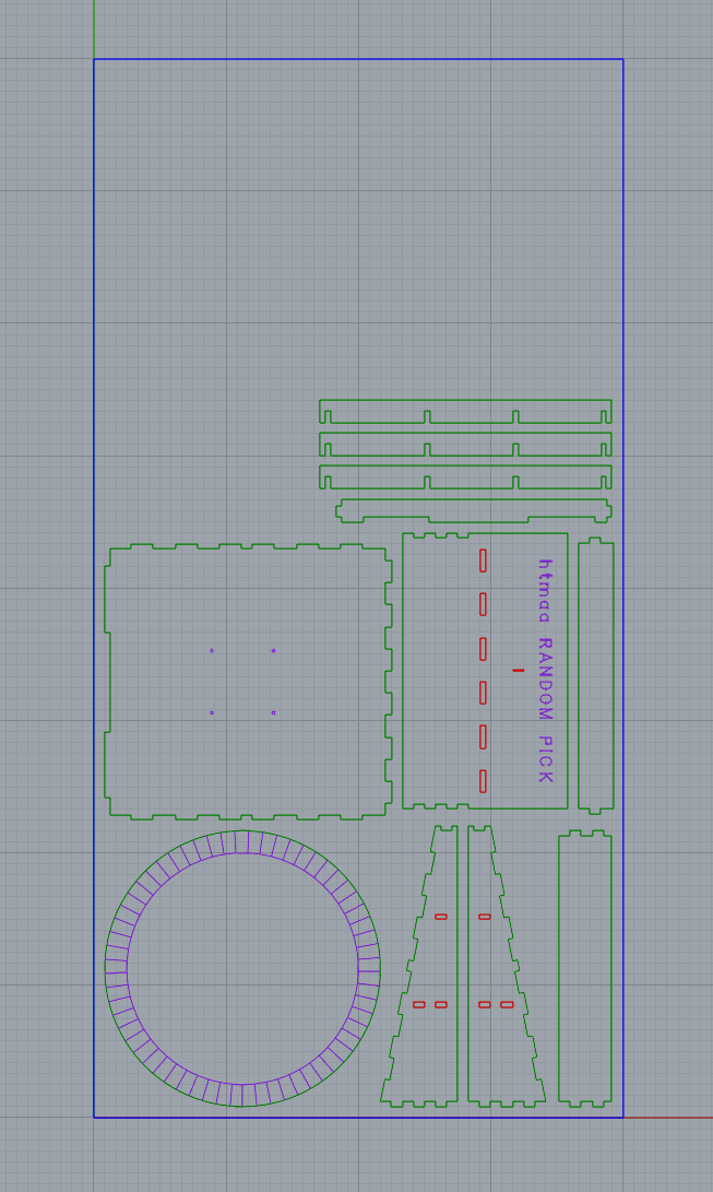
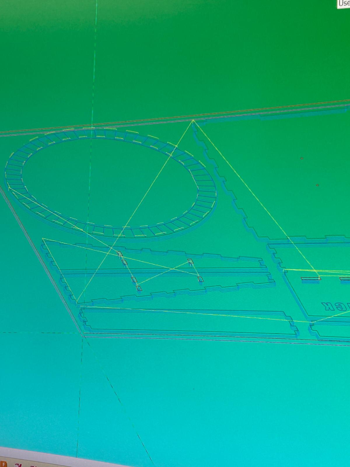
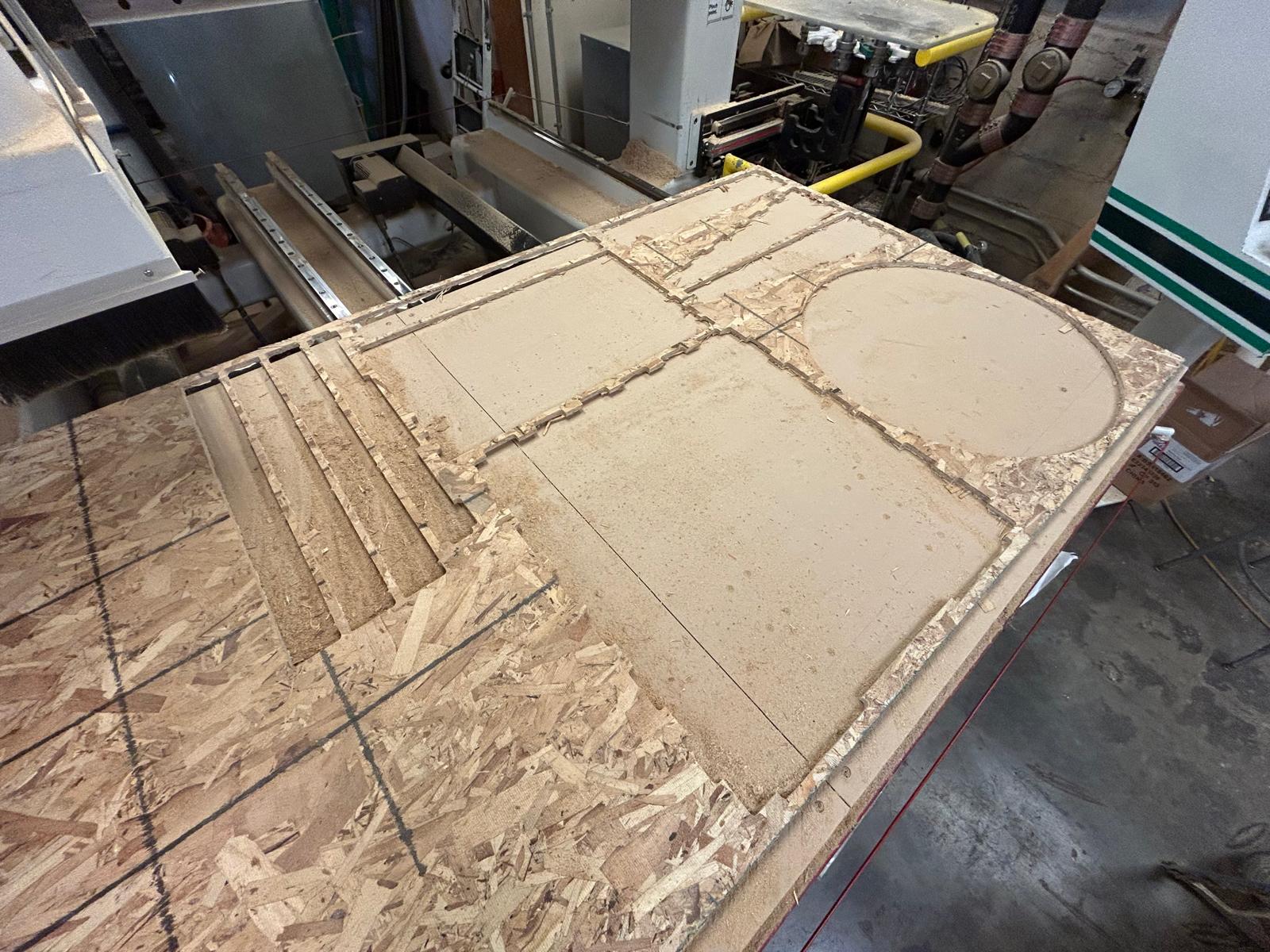
For this week’s assignment, I had several ideas on a larger scale, but they were too big to fit within a standard 48" × 96" OSB sheet. So, I started thinking ahead to my final project, which will probably require bearings to allow a surface to rotate. My idea evolved through class discussions, and I decided to create an HTMAA Random Pick Generator, inspired by the spinning “lucky wheel” games used in gambling. I modeled the design in Rhino, and once the file was ready, Dan kindly helped me prepare it for G-code generation. Unfortunately, the first file didn’t have the correct parameters, so I had to rebuild it from scratch with Chris’s help. The CNC process involved four operations: Drilling the holes Engraving the text and patterns Profile cutting the parts Chamfering (shaping) the edges It was really interesting to observe how the machine automatically switched between bits and how each bit type corresponded to a specific operation.
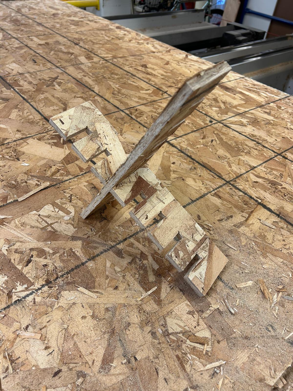

7.14
some sketches of the random generator
7.15
I 3d modeled my project so that I can understand better the structure
7.16
my parts are ready
7.17
both Dan and Chris helping me with Mastercam
7.18
I can see the engravings of the wheel
millin the holes
millin the engravings
cleaning the edges
7.19
all the pieces almost came off on their own so I couldn't take a picture of my stock with my parts on it
7.20
most of them had rough edges so I needed to clean them up with a knife

Production

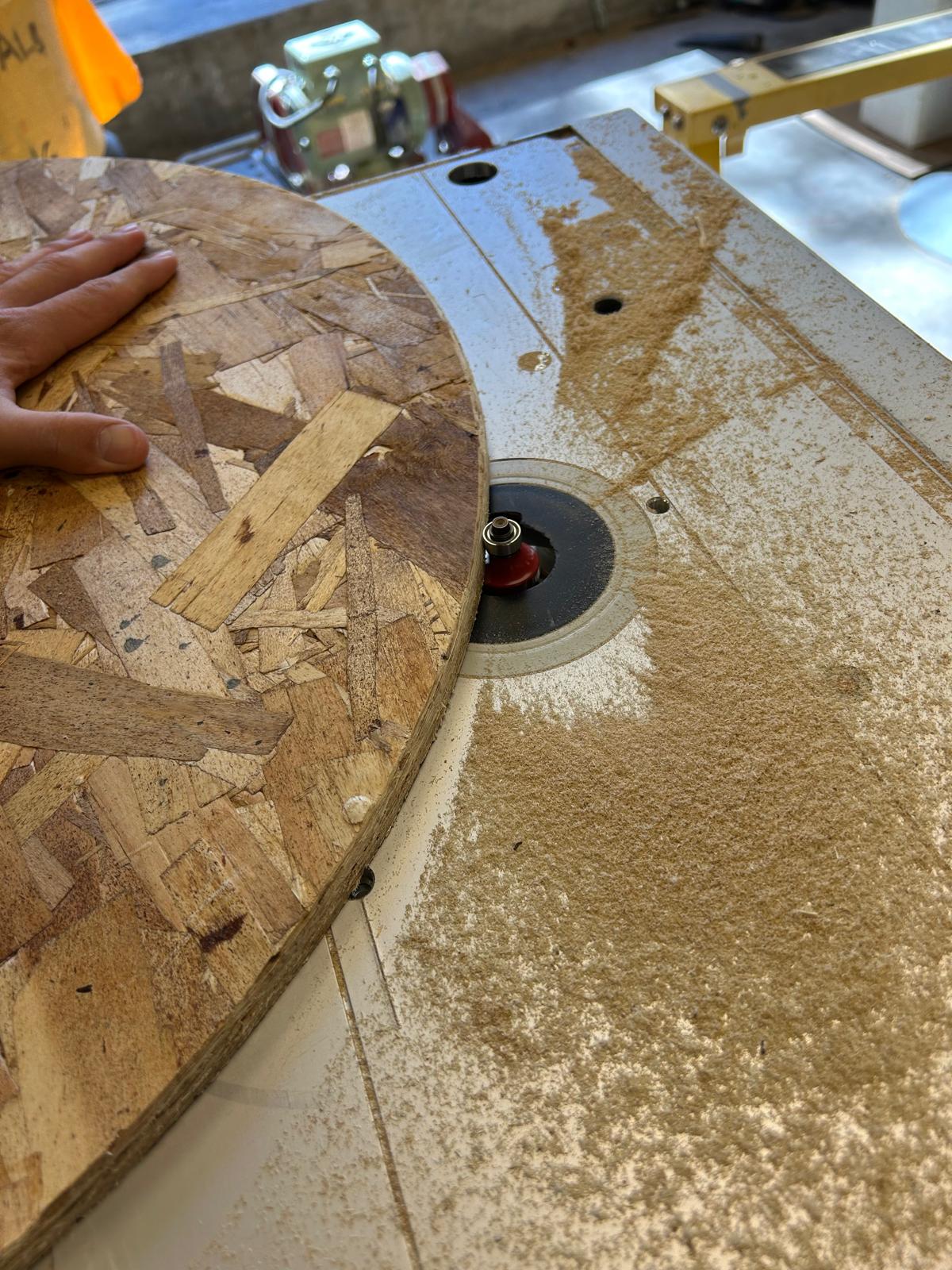
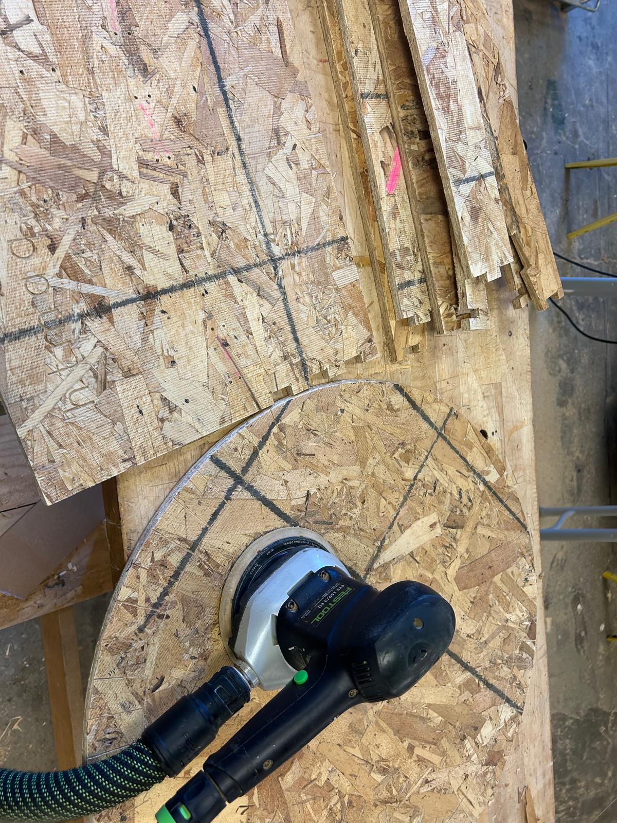
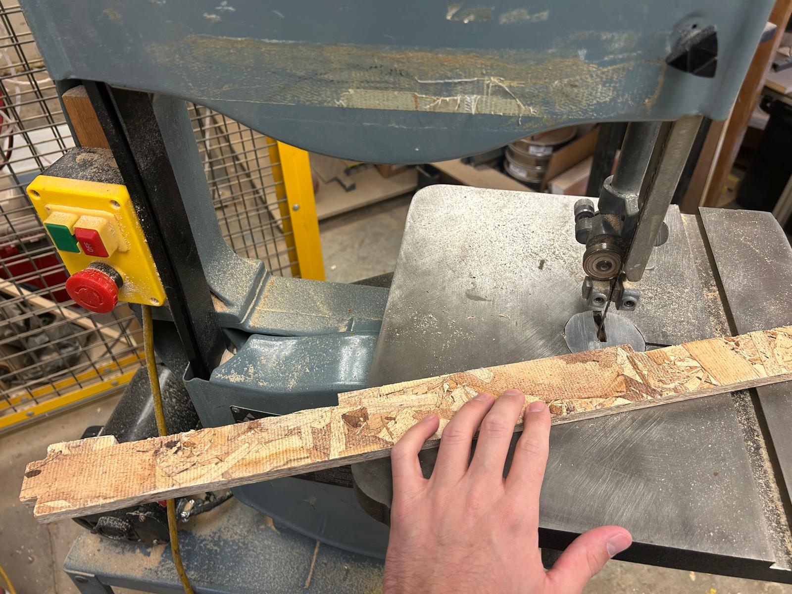
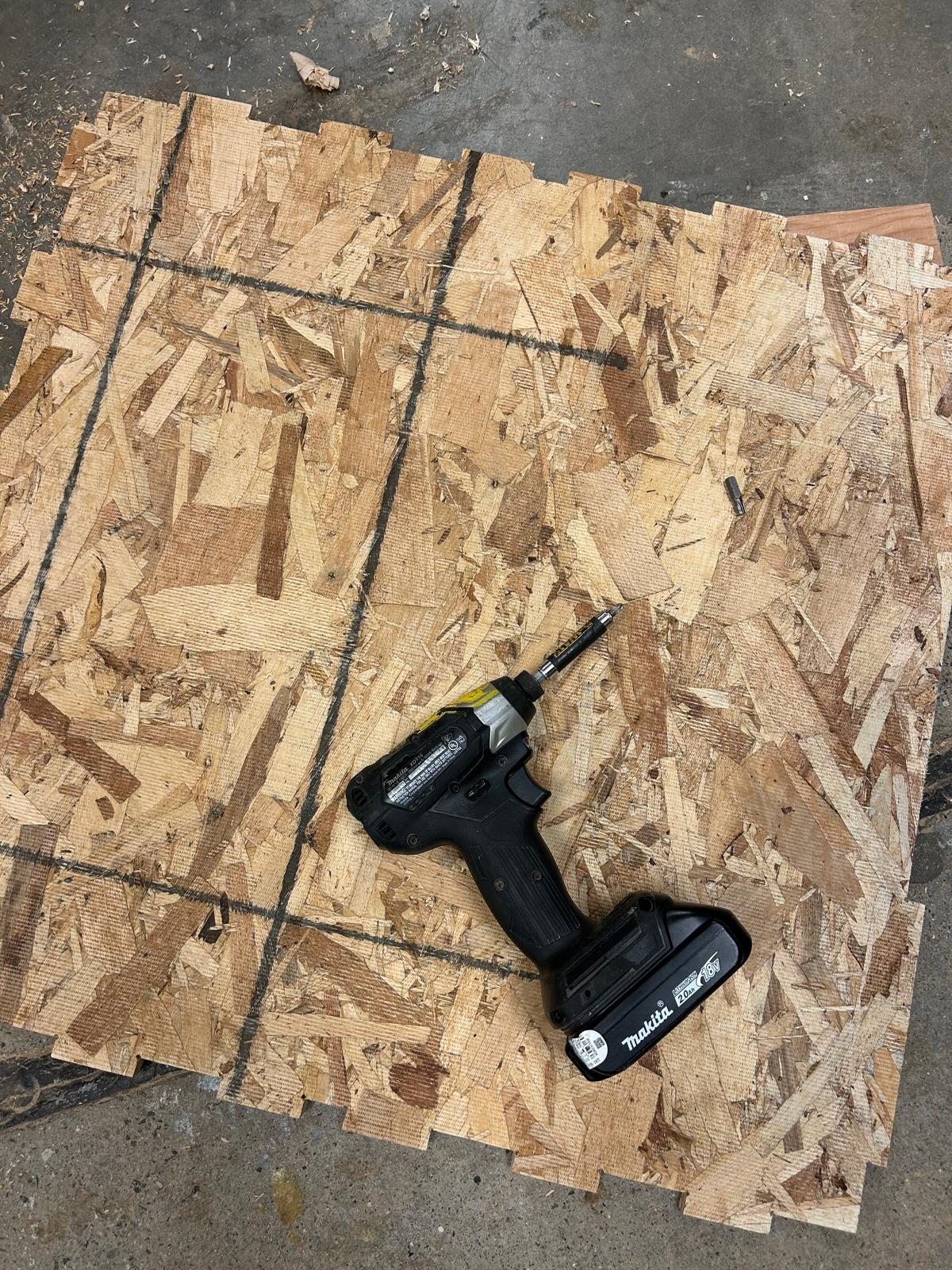
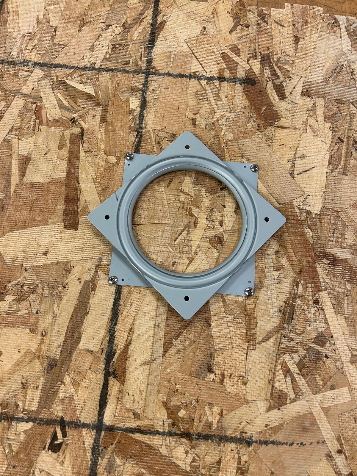
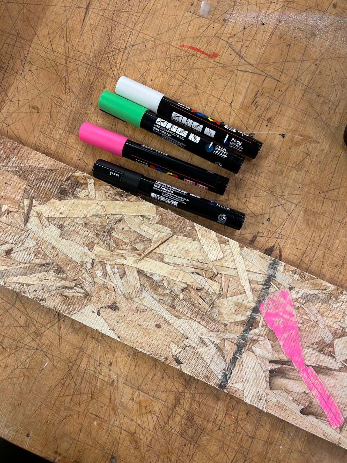
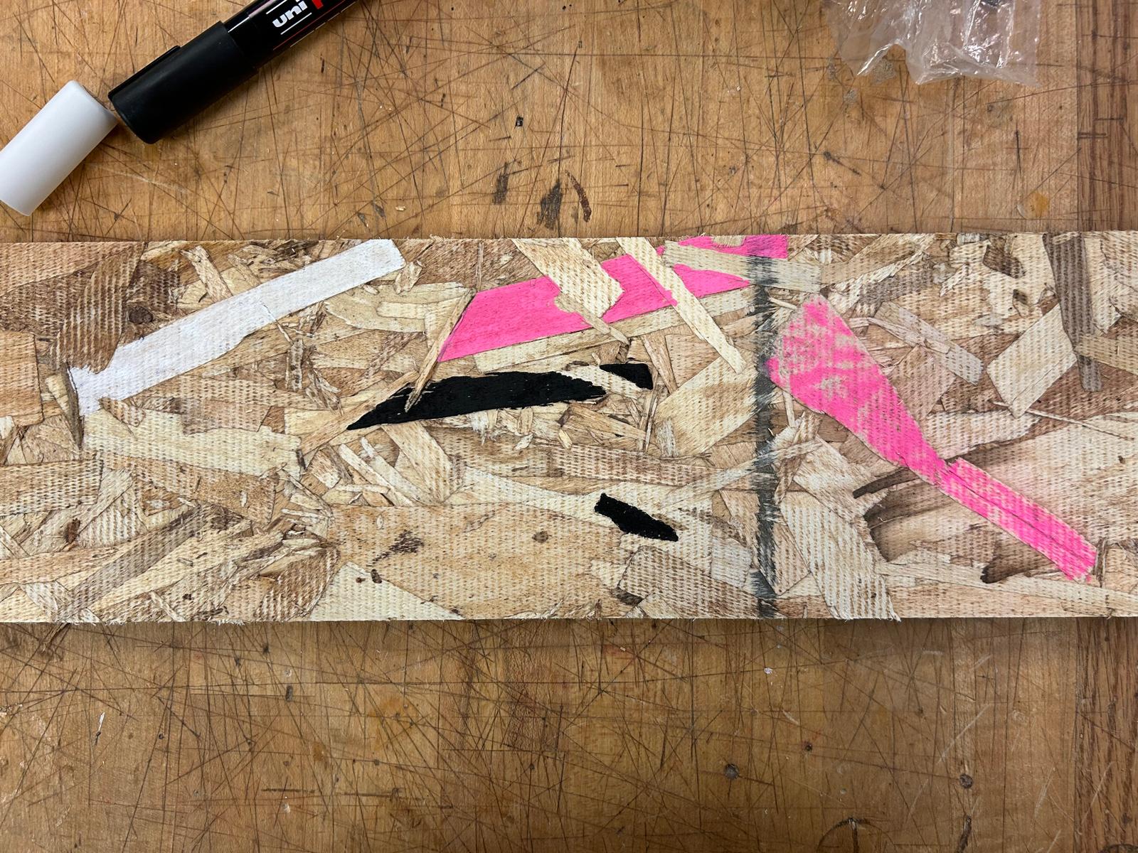
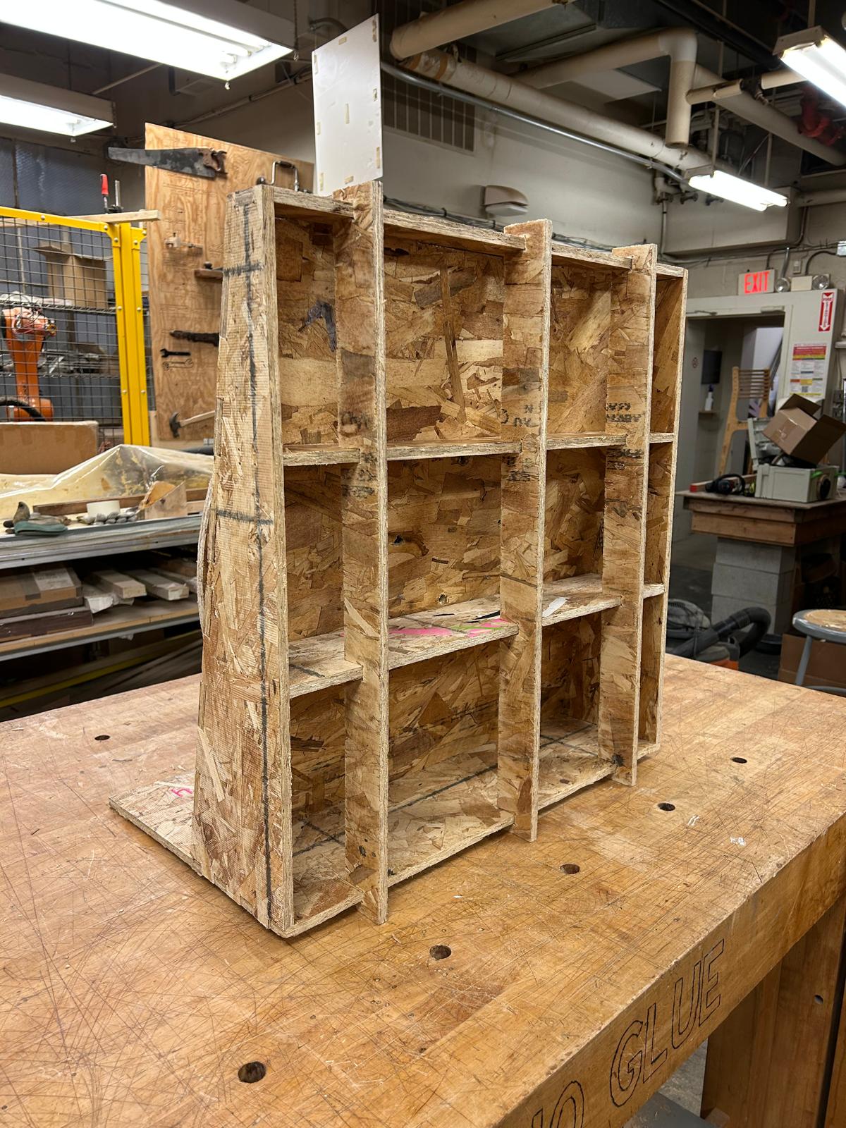
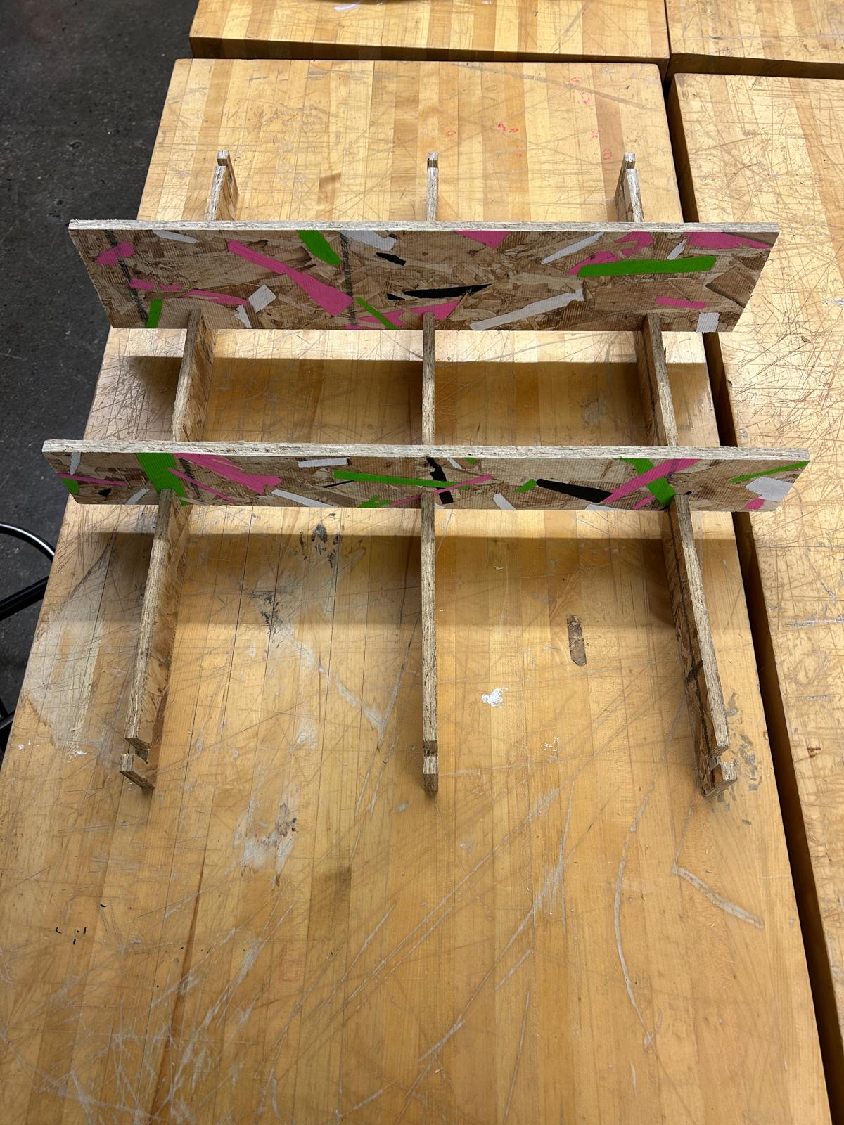
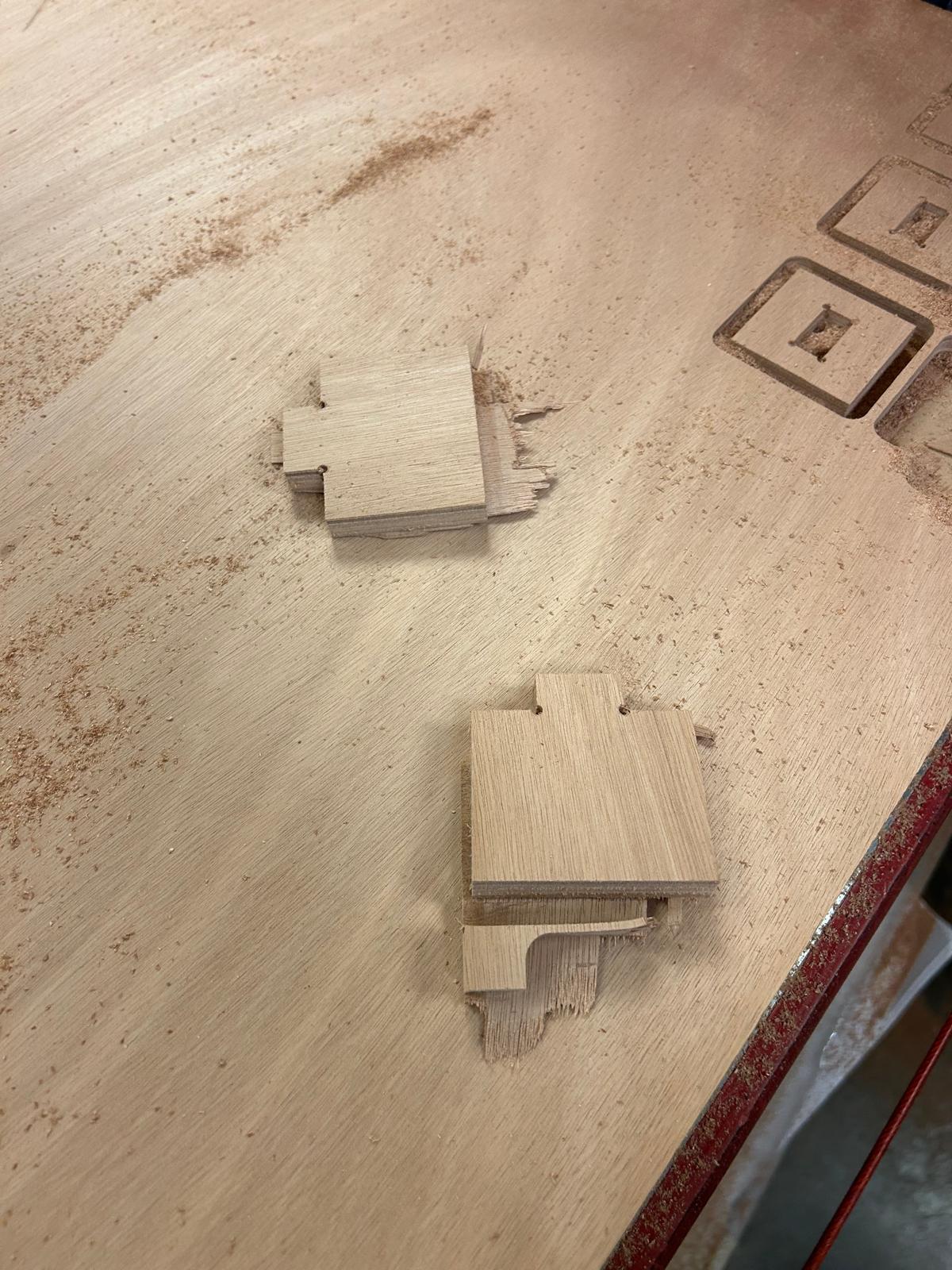
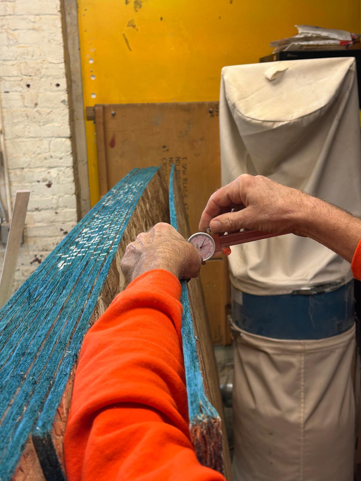
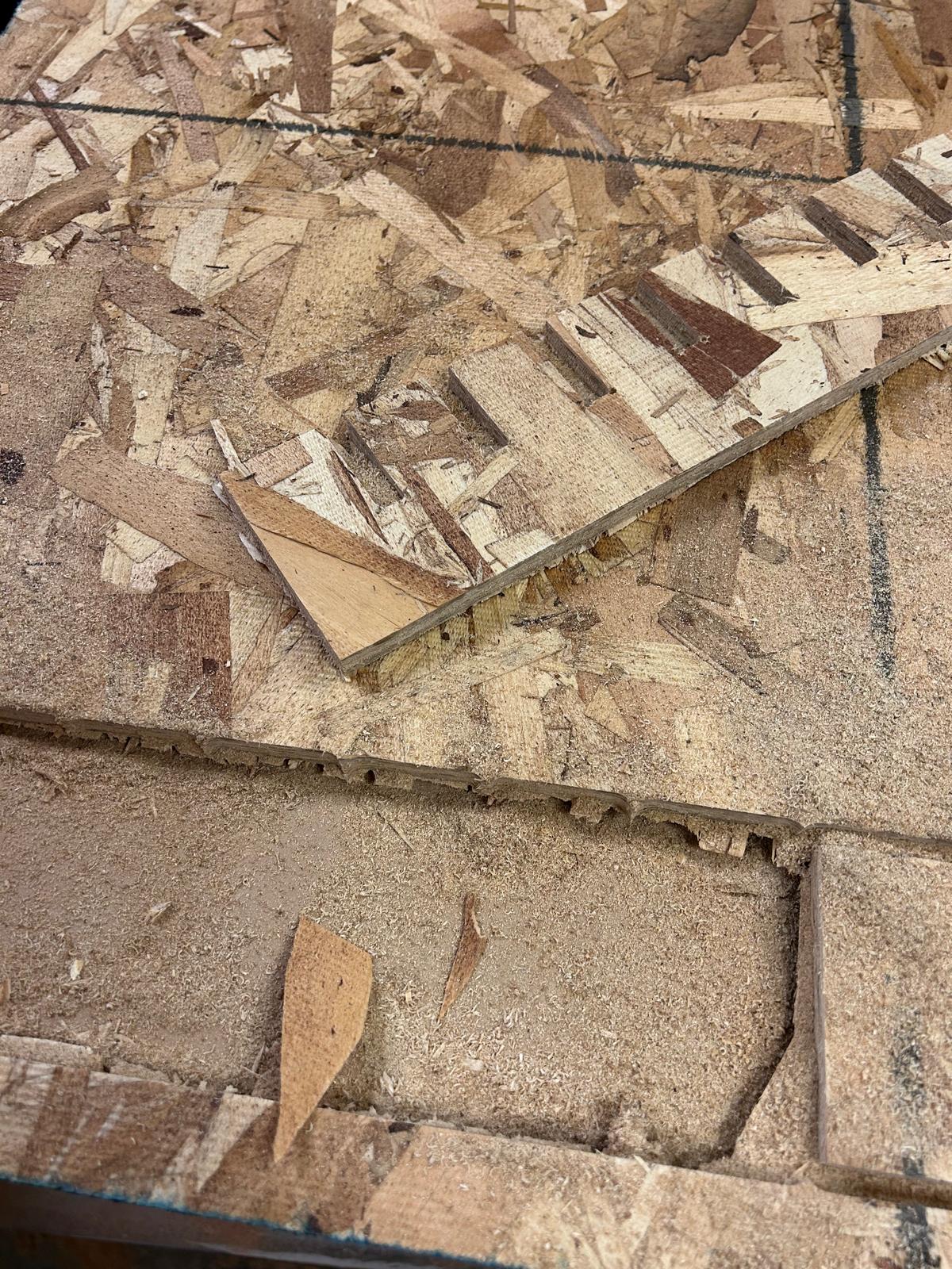
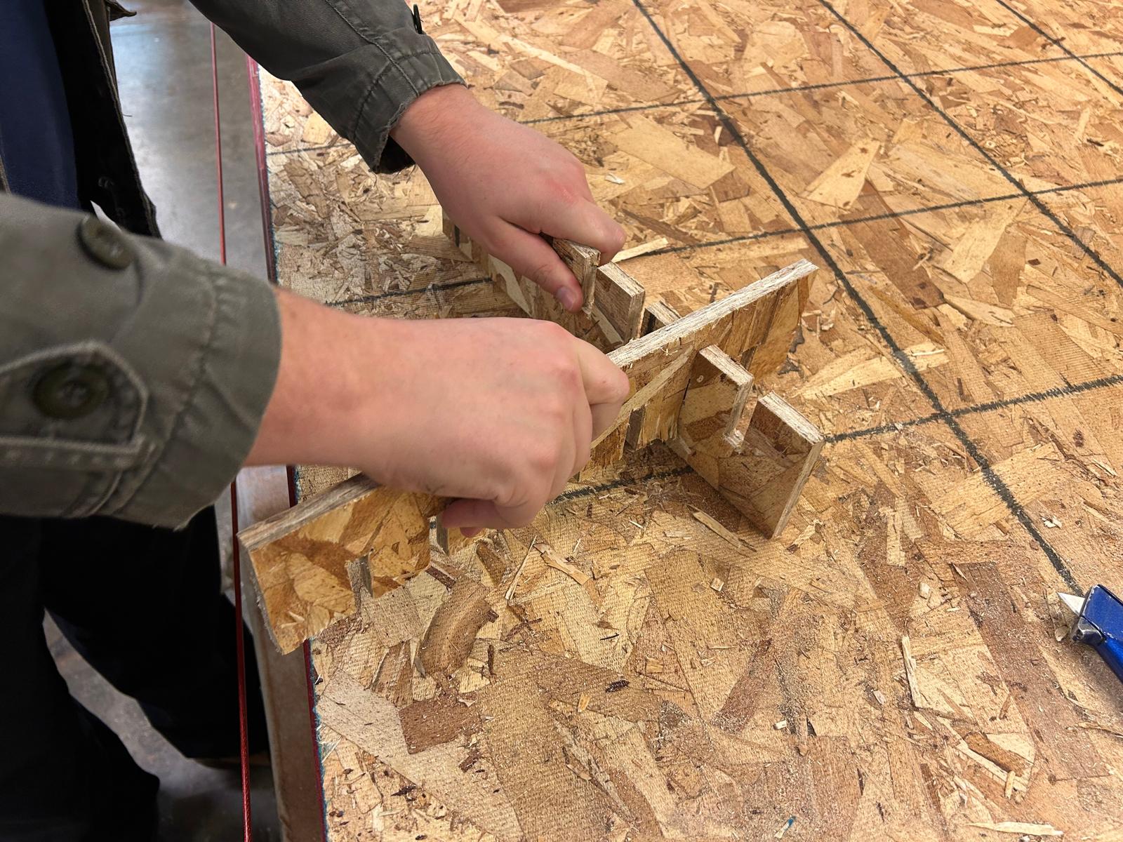
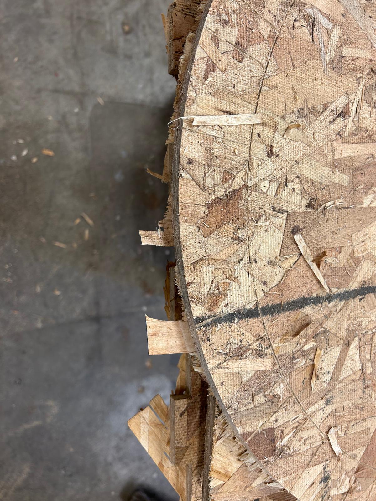
Most of the pieces were cut accurately, except for one that I hadn’t noticed was misaligned from the beginning. I sanded all the parts to smooth the surfaces and remove splinters, then recut the faulty piece. Chris suggested using the table saw for a faster fix. I transferred the measurements onto a new OSB sheet, and Chris helped me make the precise cut. After that, I adjusted the stock edges so the pieces would fit together properly. The most challenging part of the whole process was installing the Lazy Susan bearing. I ordered one from Home Depot for about seven dollars. To attach it, I had to drill offset holes on one side to allow access for the screws from the opposite wooden plate. Once everything was assembled, I moved on to the artistic finishing using Posca markers. I experimented with several color combinations, but mainly used black to emphasize the OSB’s layered composition.

7.21
I smoothed the edges of the wheel so that it would be less rough when someone wants to touch it and spin it
7.22
I also sanded all the parts to get rid of excess material and spikes
7.23
I miscalculated one piece and I had to recut it using the tablesaw and the bandsaw
7.24
the most challenging part of this week was to figure out a way to screaw the lady suzan on the two wooden pieces
7.25
here are the holes that I drilled provisioning the position of the four screws the will hold the wheel
7.26
I screwed the lasy suzan to the bottom part
7.27
here are all of my pieces before I assemble them
7.28
seeing these posca markers last week made me wonder if it would have been better if I paint some parts of the osb
7.29
I tested the colors
7.30
and I assembled the pieces to see how the wheel spins
7.31
I also checked the performance of my structure cause intentionally I didn't want to use glue or screws and hopefully it ended up being very stable
7.32
I checked all the names of my classmates
7.32
and I prepared a file so that I could print it. At this point I was still not sure how to write the names down the wheel
7.32
I decided to cut the names and glue them on the wheel
7.33
I also put the arrow of the random picker
7.34
I dismantled the structure and colored all the pieces cause osb was a bit dull compared to the colored parts
7.35
and here I rebuild the model
7.36
7.37
7.39
7.38
ready to generate some names!!