week 8:input devices
Gert's training
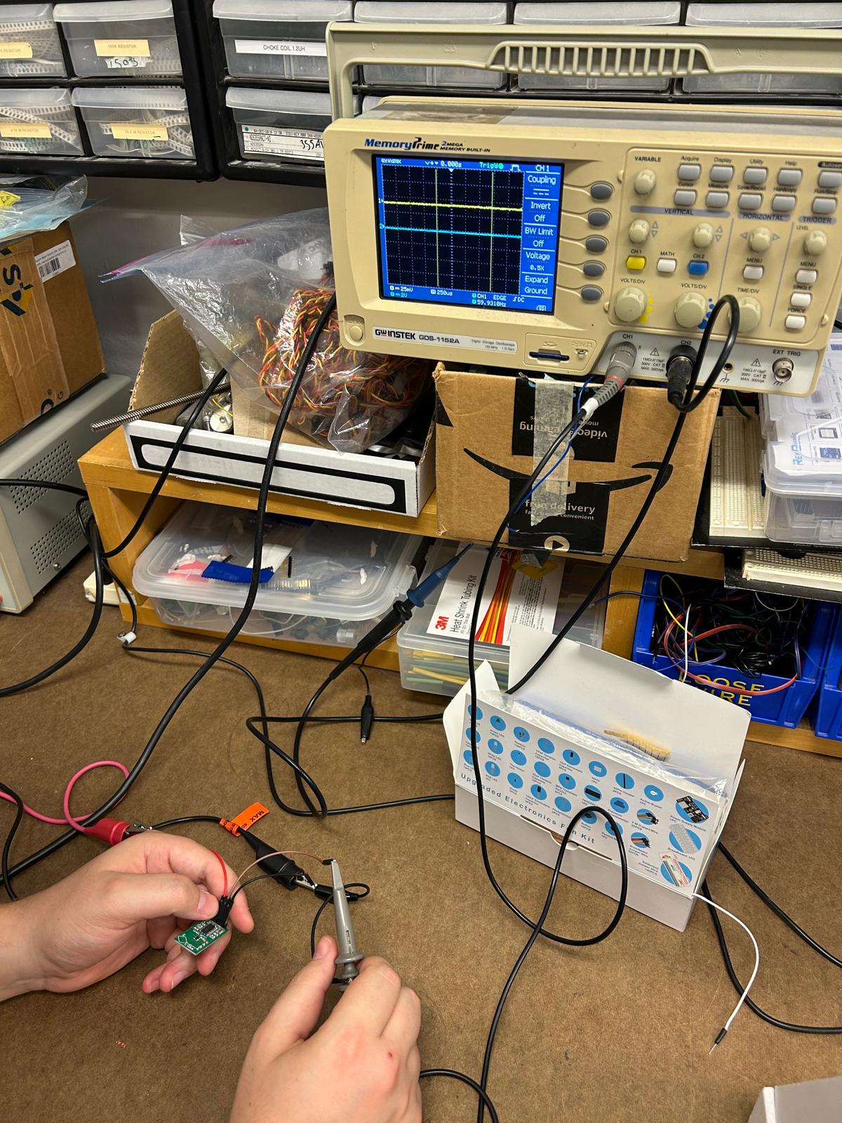
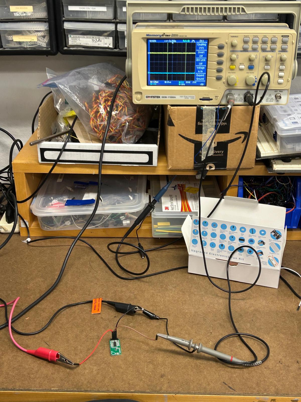
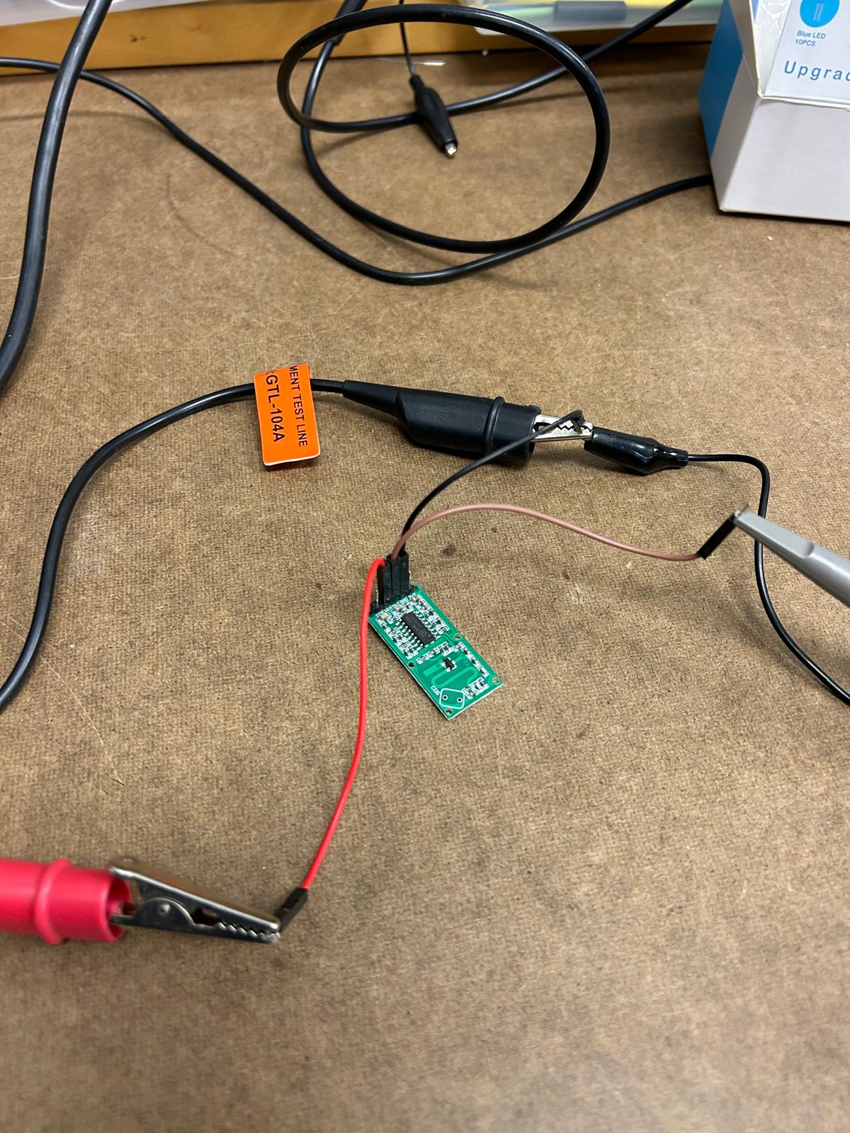
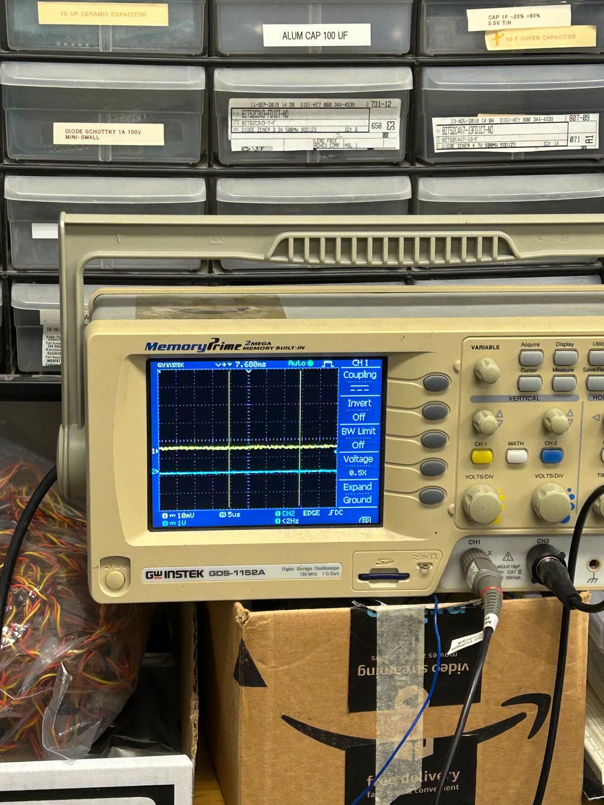
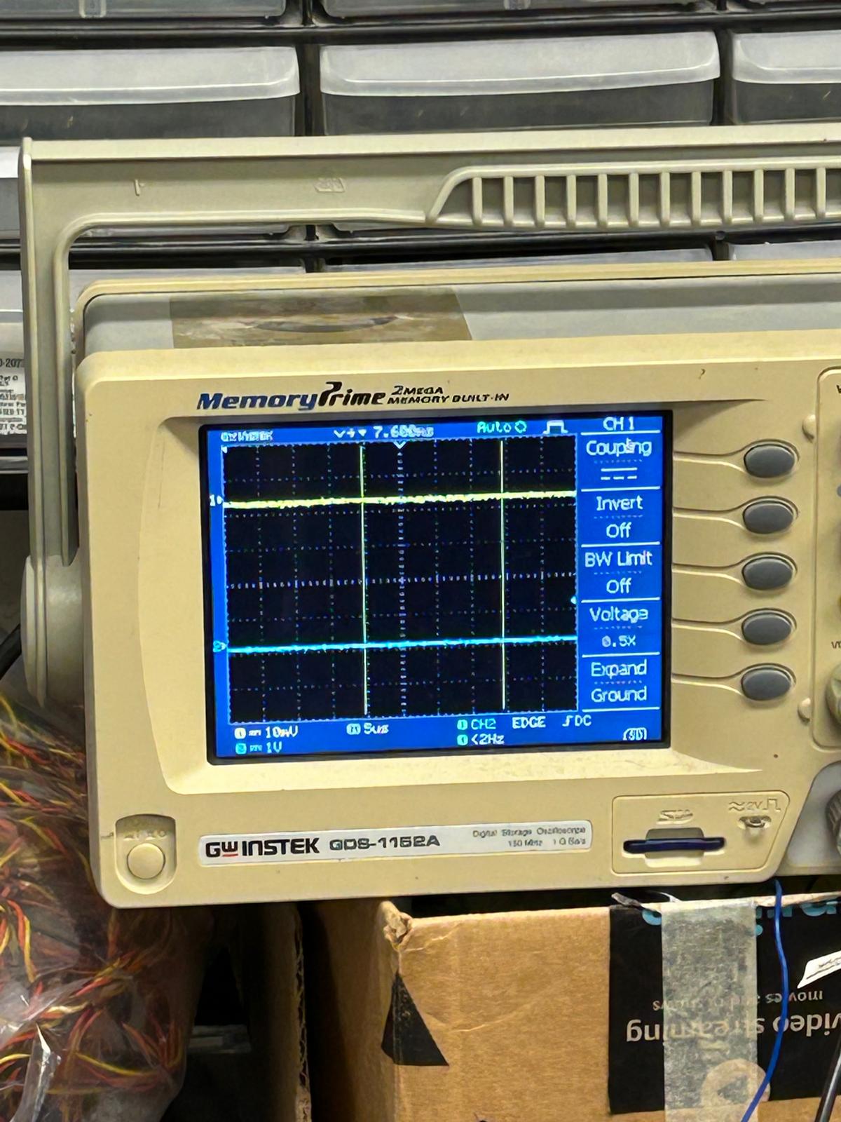
During this week’s training, Gert showed us how to use the oscilloscope to verify whether our motion detection sensor was working properly. By connecting it to the oscilloscope, we could visualize the sensor’s signal patterns in real time. Two waveform lines appeared on the screen, each representing a different channel of the sensor’s output. When the sensor detected movement, the first line began to shift closer to the second—showing a clear correlation between the motion in front of the sensor and the signal change on the display
week 5 revision
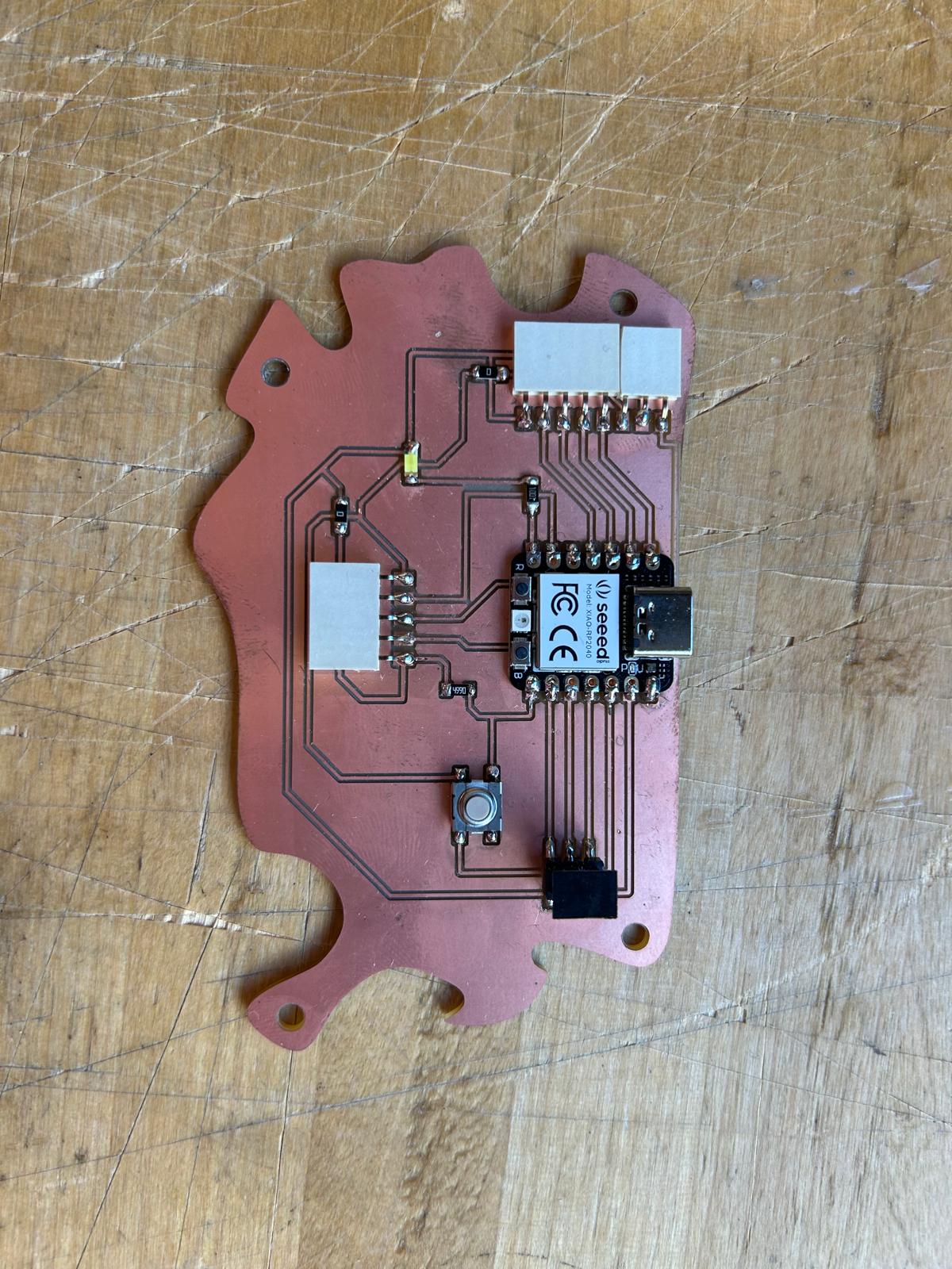
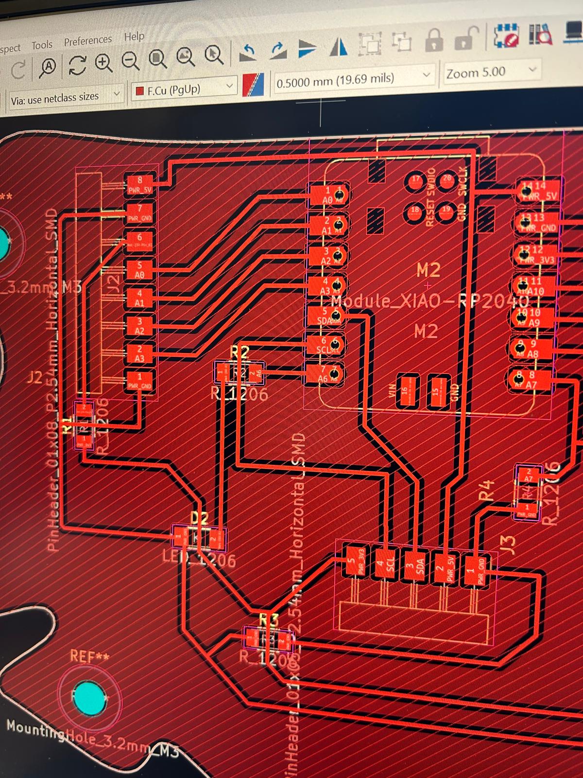
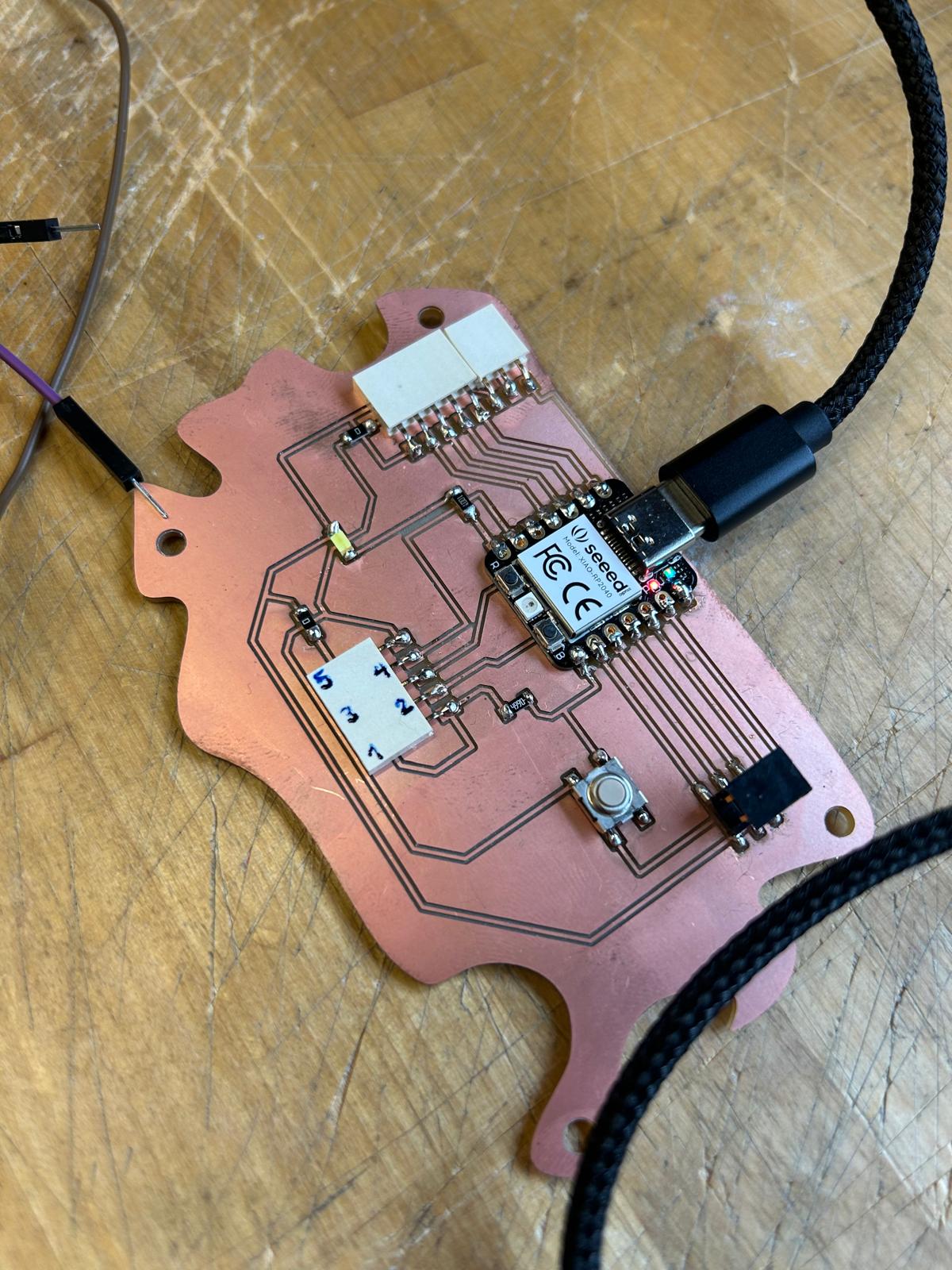
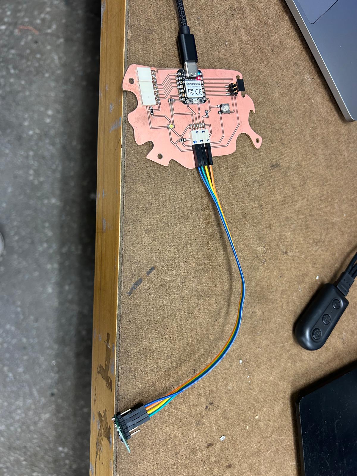
For this week’s assignment, I decided to reuse the PCB board I designed back in Week 5. The reference from Adrián Torres’ Fab Academy documentation turned out to be extremely helpful when planning the pin layout and connections. It seems that the board I designed is well-suited not only for controlling the servo motor I used in weeks 5 and 6, but also for experimenting with various input devices.
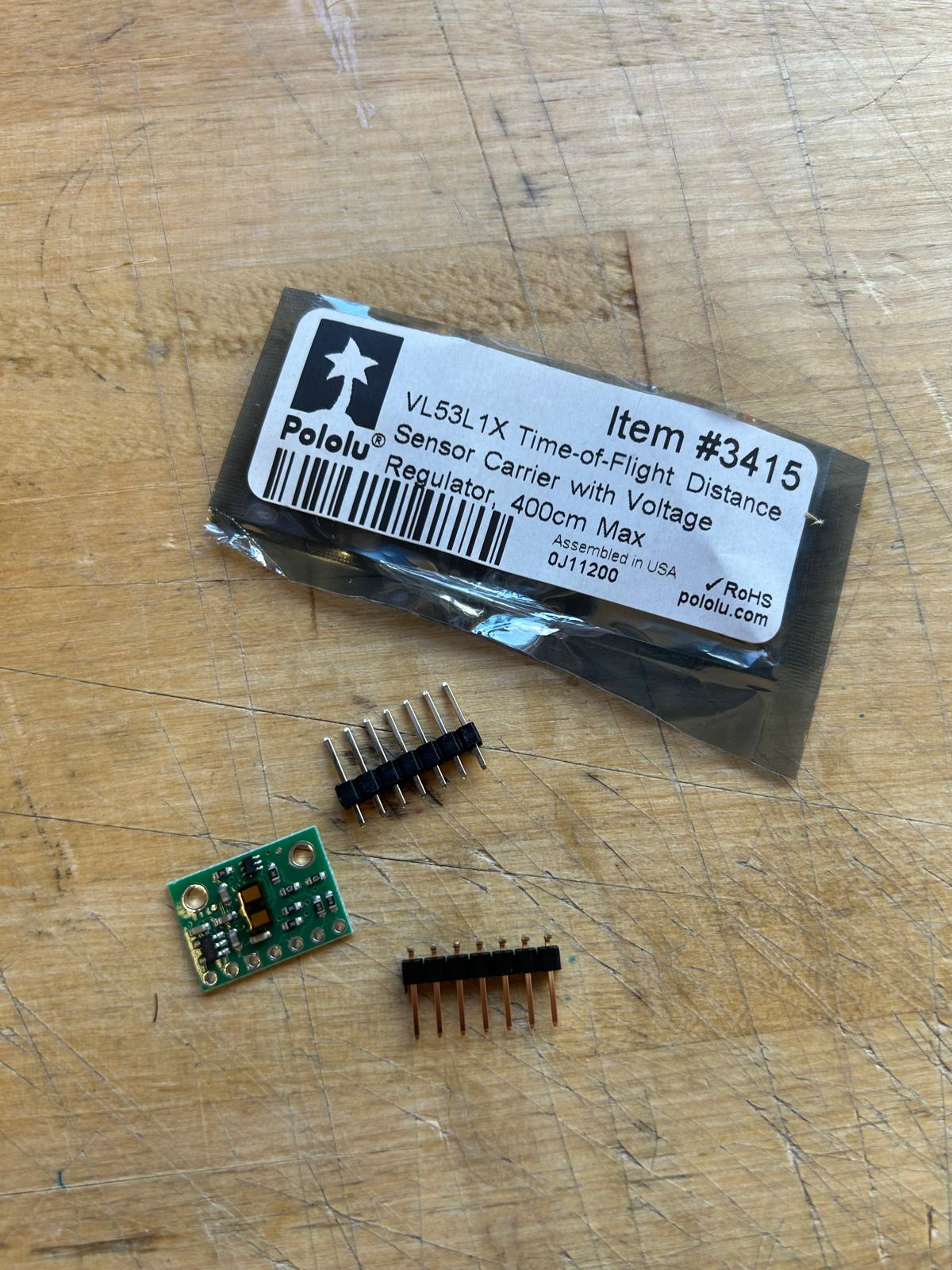
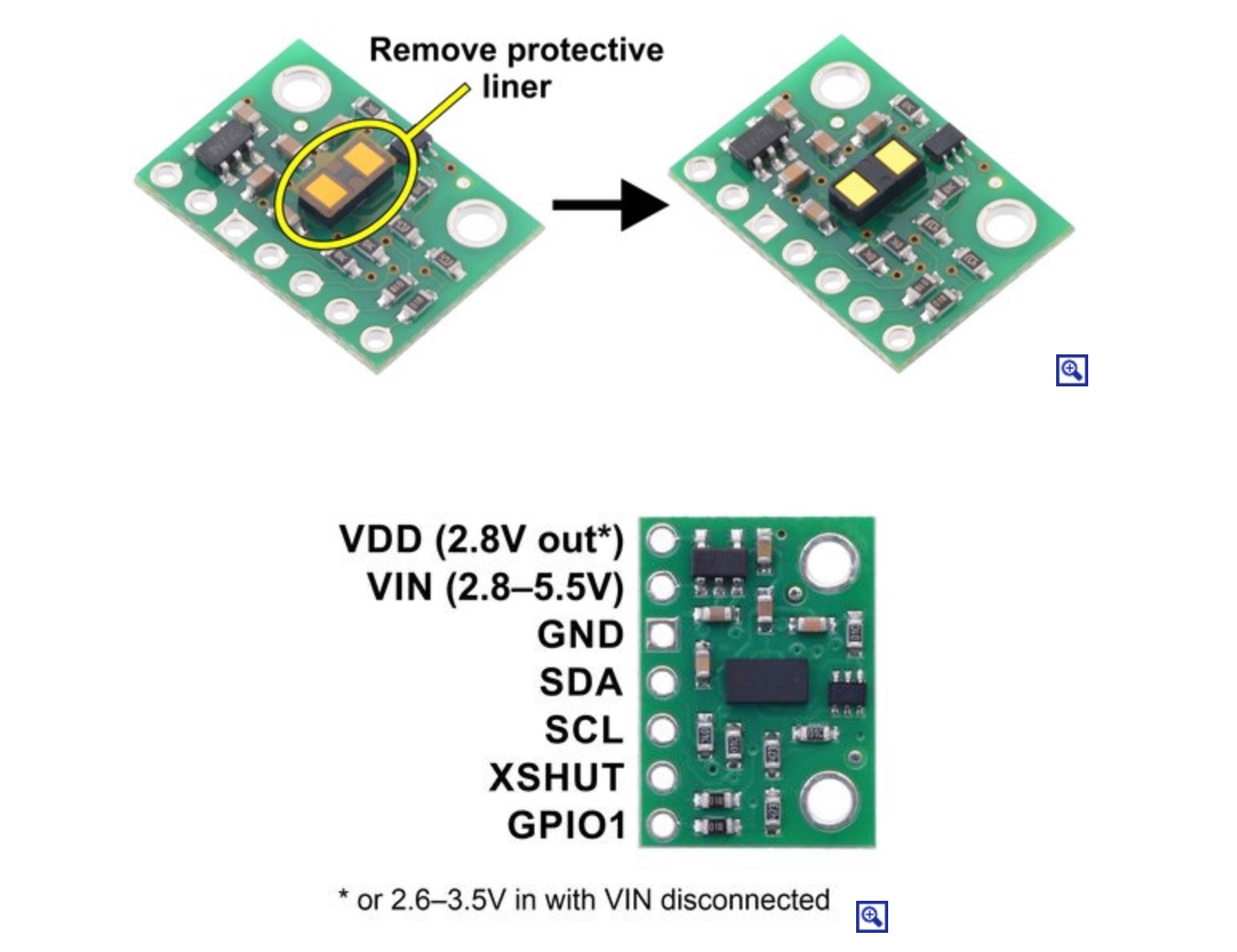
Since I am still questioning which kind of detectors would be the best to include in my final project I decided to use a distance detector sensor

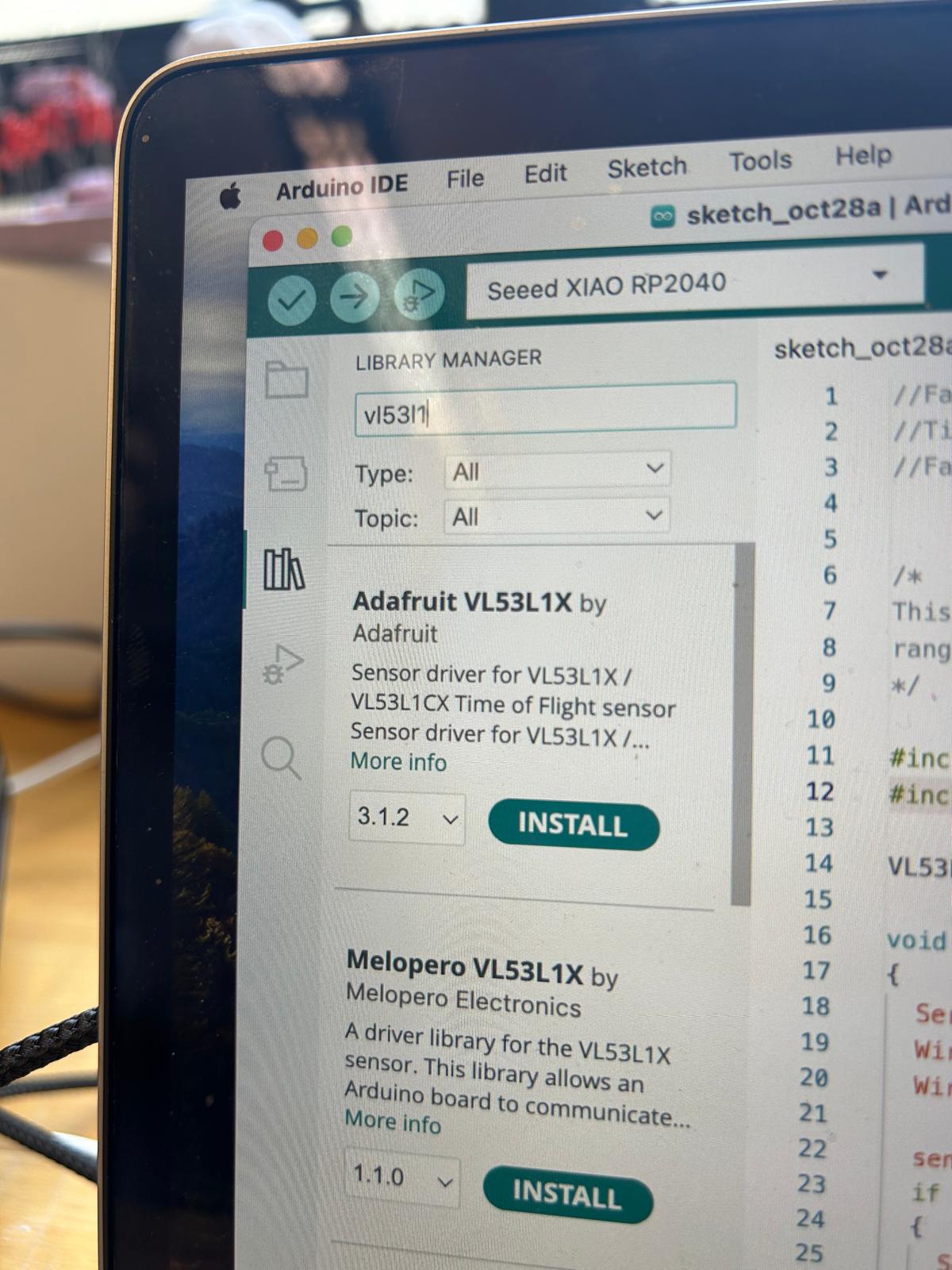
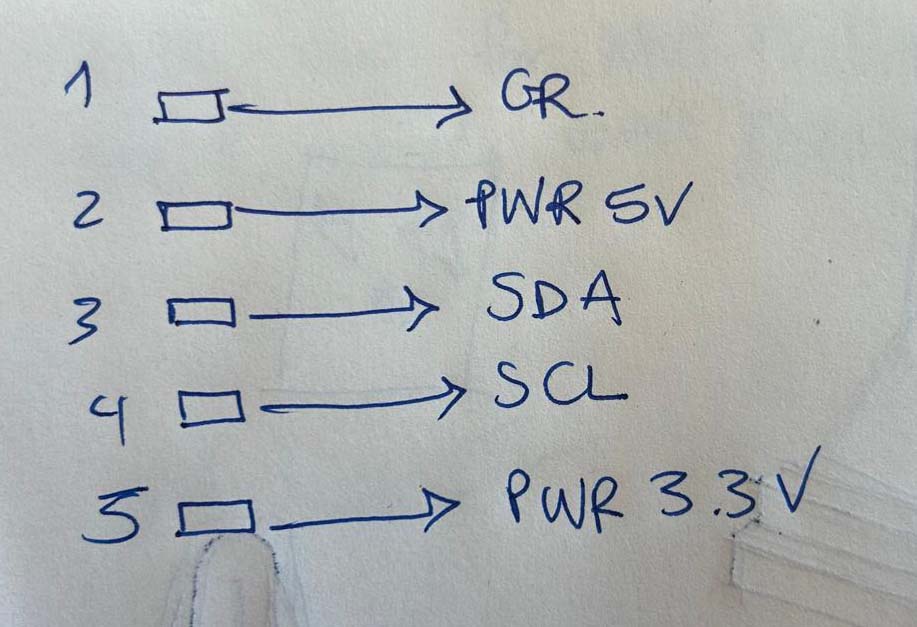
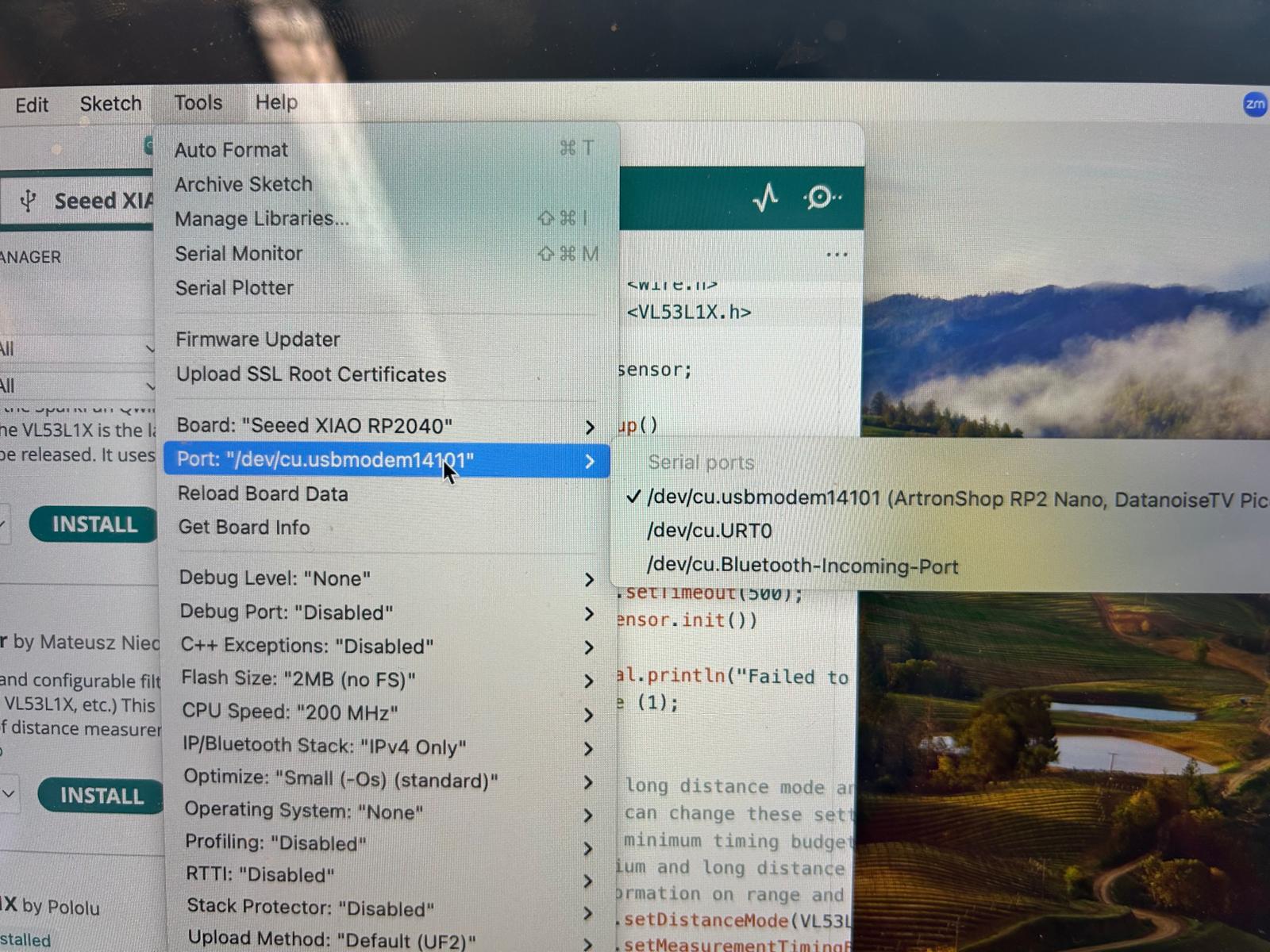
//Fab Academy 2023 - Fab Lab León
//Time of Flight VL53L1X
//Fab-Xiao


/*
This example shows how to take simple range measurements with the VL53L1X. The
range readings are in units of mm.
*/

#include
#include

VL53L1X sensor;

void setup()
{
  Serial.begin(115200);
  Wire.begin();
  Wire.setClock(400000); // use 400 kHz I2C

  sensor.setTimeout(500);
  if (!sensor.init())
  {
    Serial.println("Failed to detect and initialize sensor!");
    while (1);
  }

  // Use long distance mode and allow up to 50000 us (50 ms) for a measurement.
  // You can change these settings to adjust the performance of the sensor, but
  // the minimum timing budget is 20 ms for short distance mode and 33 ms for
  // medium and long distance modes. See the VL53L1X datasheet for more
  // information on range and timing limits.
  sensor.setDistanceMode(VL53L1X::Long);
  sensor.setMeasurementTimingBudget(50000);

  // Start continuous readings at a rate of one measurement every 50 ms (the
  // inter-measurement period). This period should be at least as long as the
  // timing budget.
  sensor.startContinuous(50);
}

void loop()
{
  Serial.print(sensor.read());
  if (sensor.timeoutOccurred()) { Serial.print(" TIMEOUT"); }

  Serial.println();
}
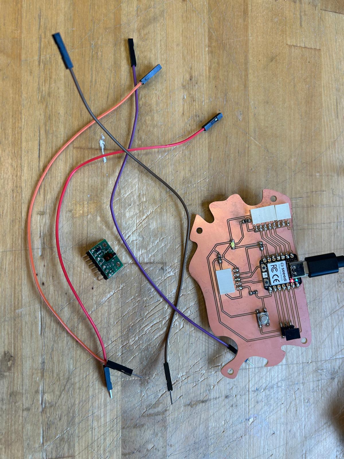
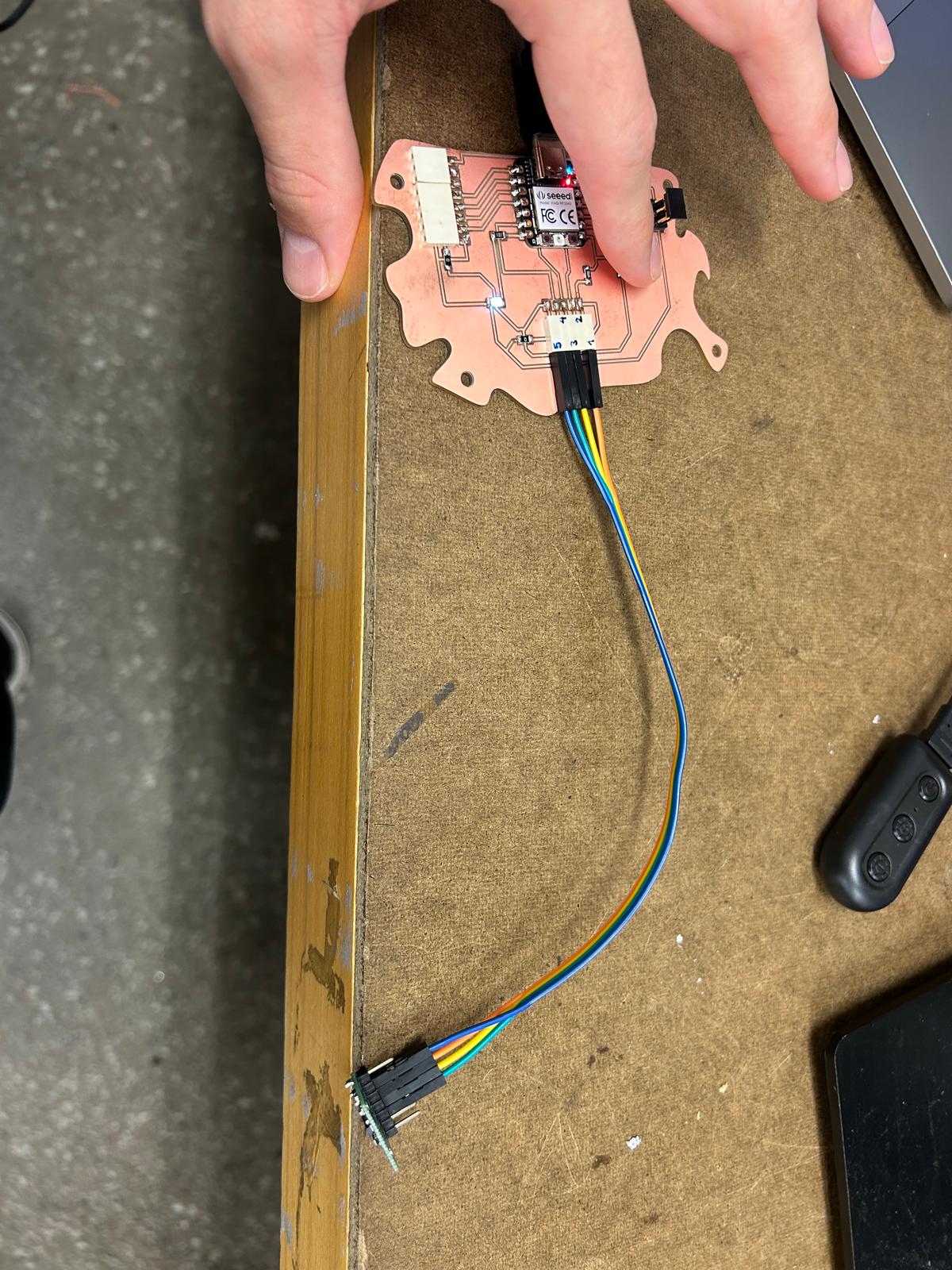
The code didn’t work as expected. Since I was confident that my board was correctly designed, I realized the issue might be in the code itself or possibly in the cable connections. To verify the board’s functionality, I modified the code to include LED interaction. Seeing a simple blinking light confirmed that the board was operating properly, but the sensor still showed no response. From that point on, my focus shifted to troubleshooting and identifying the source of the malfunction.
At this point I changed the code again and I thought that a way to check if my sensor wors is if I press the button. then I wanted the light to be constantly on and depending on the brightness of the LED this would indicate if an object is close or far from the sensor. I was not sure what to change and I asked chat gtp. CHat gtp confirmed that there was no errors on the code and that all my previous actions were correct based on the results that I had so far.
// Fab Academy 2023 - Fab Lab León
// VL53L1X Distance Sensor + Button + LED Brightness Control

#include
#include

VL53L1X sensor;

// Pin definitions
const int ledPin = 0;       // LED pin (RP2040 pin 0)
const int buttonPin = 1;    // Button pin (RP2040 pin 1)

// Distance range for brightness mapping (in mm)
const int minDistance = 50;    // closer than this → max brightness
const int maxDistance = 800;   // farther than this → dimmest

void setup()
{
  Serial.begin(115200);
  delay(500);

  pinMode(ledPin, OUTPUT);
  pinMode(buttonPin, INPUT);

  // Initialize I2C for VL53L1X
  Wire.setSDA(D4);
  Wire.setSCL(D5);
  Wire.begin();
  Wire.setClock(400000);

  // Initialize the VL53L1X sensor
  sensor.setTimeout(500);
  if (!sensor.init()) {
    Serial.println("Failed to detect and initialize sensor!");
    while (1) {
      digitalWrite(ledPin, !digitalRead(ledPin)); // blink to show error
      delay(300);
    }
  }

  sensor.setDistanceMode(VL53L1X::Long);
  sensor.setMeasurementTimingBudget(50000);
  sensor.startContinuous(50);

  Serial.println("VL53L1X ready!");
}

void loop()
{
  int buttonState = digitalRead(buttonPin);

  if (buttonState == HIGH) {
    uint16_t distance = sensor.read();

    if (sensor.timeoutOccurred()) {
      Serial.println("TIMEOUT");
      return;
    }

    Serial.print("Distance: ");
    Serial.print(distance);
    Serial.println(" mm");

    // Limit the distance range
    distance = constrain(distance, minDistance, maxDistance);

    // Map distance → brightness (closer = brighter)
    int brightness = map(distance, maxDistance, minDistance, 0, 255);

    // Apply brightness via PWM
    analogWrite(ledPin, brightness);

  } else {
    // Button not pressed → LED off
    digitalWrite(ledPin, LOW);
  }

  delay(50);
}