week 9:output devices
Gert's training
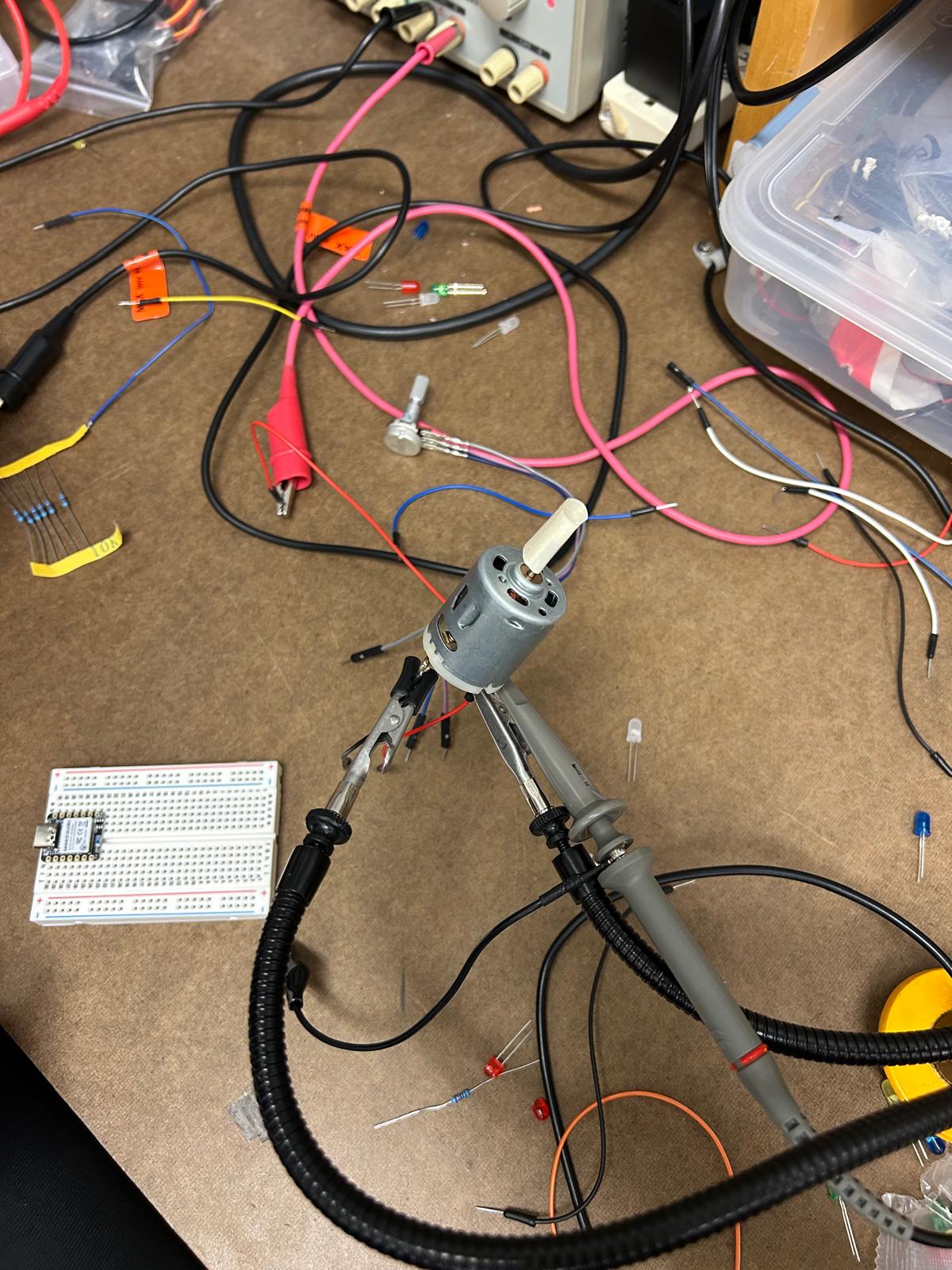
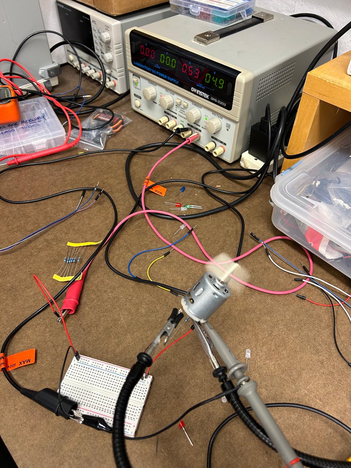
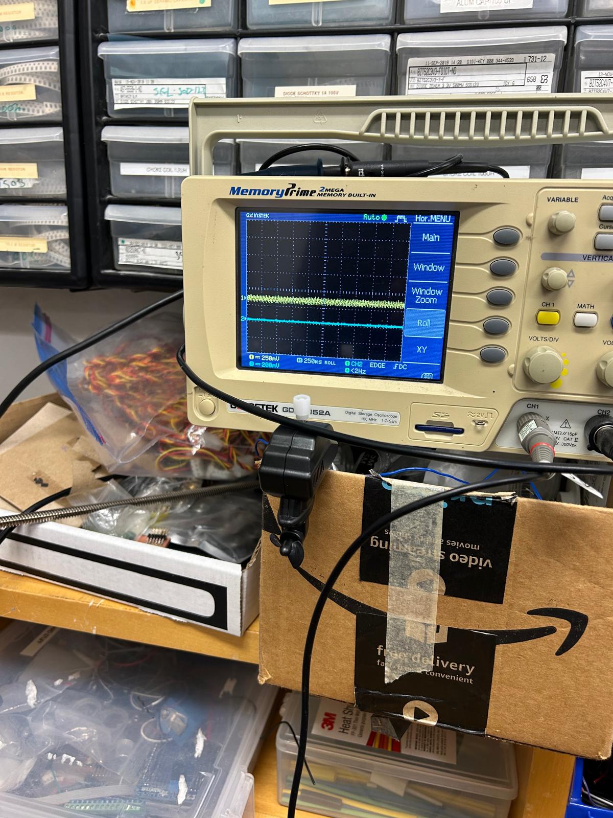
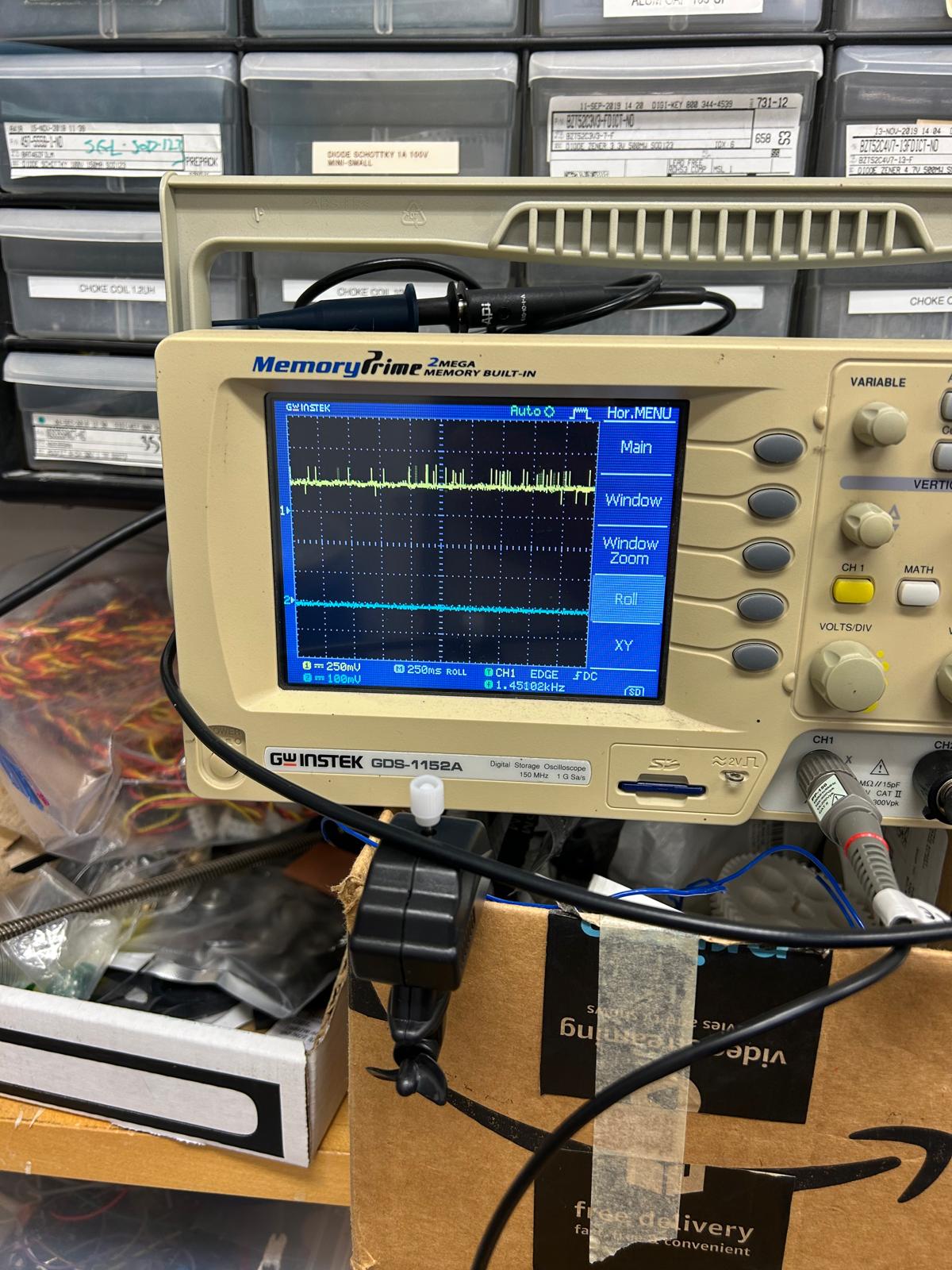
During this week’s training, Gert showed us how to use the oscilloscope to check if the power voltage influences the performance of an output
new iteration
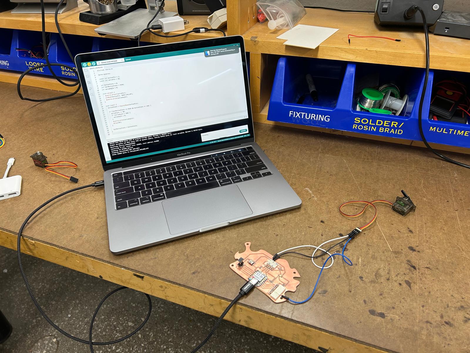
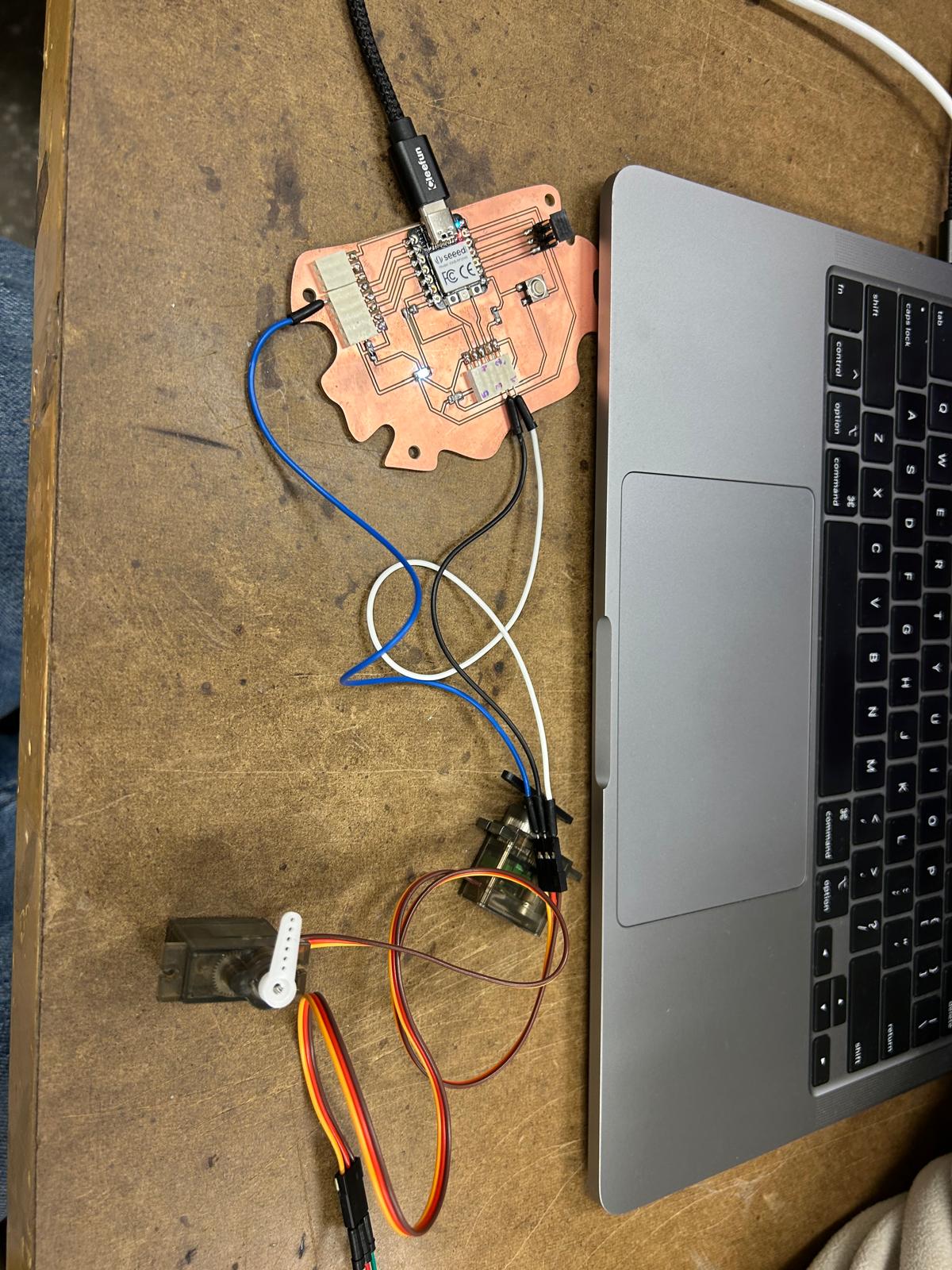
Building on the board I designed during weeks five and six, this week’s assignment focused on extending its functionality rather than creating a completely new design. To fulfill the requirements of the assignment, I decided to work with the same board and explore its limits by adding support for additional servo motors. The intention was to test how the existing design would perform under increased load and more complex control demands.
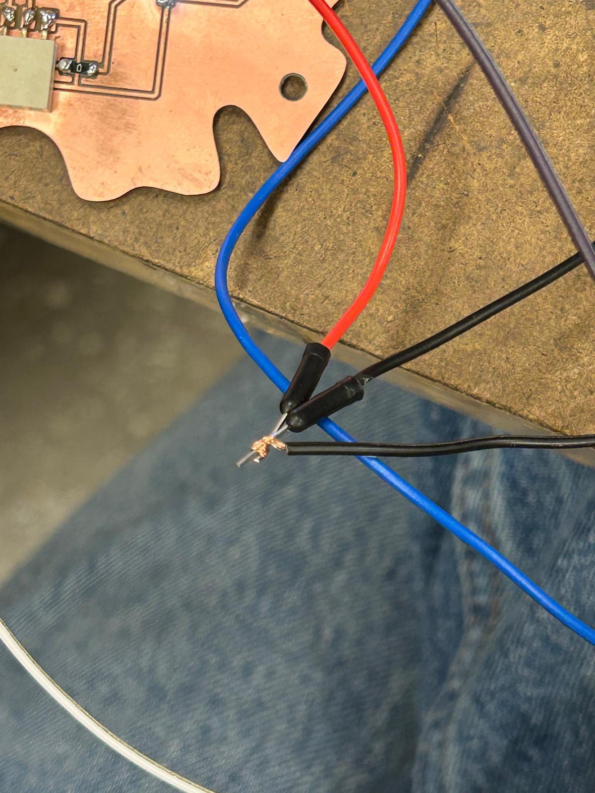
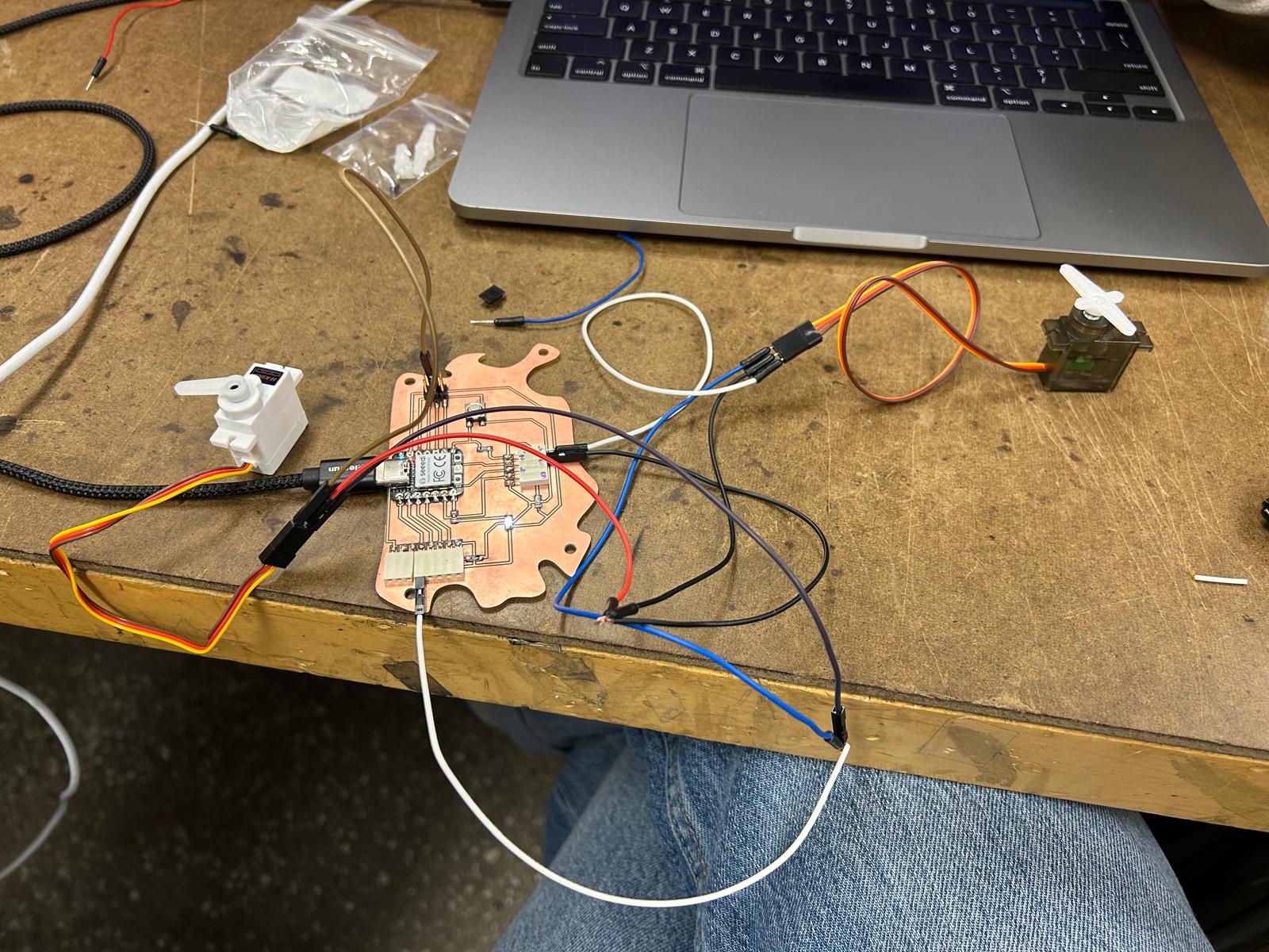
By using the same board as a base, I was able to evaluate whether the original layout and connections were flexible enough to accommodate extra components without major changes. This process highlighted important considerations such as power distribution, signal routing, and overall stability when multiple servos are connected and operating simultaneously. Testing the performance of the servos also made it possible to observe how reliably the board handles multiple outputs and whether any limitations become apparent.
#include

Servo myservo;

const int buttonPin = 1;
const int servoPin = 26;
const int ledPin = 0;

int buttonState = 0;
int lastButtonState = LOW;
int servoAngle = 0;

void setup() {
  myservo.attach(servoPin);
  pinMode(buttonPin, INPUT);
  pinMode(ledPin, OUTPUT);
  digitalWrite(ledPin, HIGH); // LED on initially

  servoAngle = 0;
  myservo.write(servoAngle);
}

void loop() {
  buttonState = digitalRead(buttonPin);

  if (lastButtonState == LOW && buttonState == HIGH) {
    digitalWrite(ledPin, LOW);

    // Rotate +90° but wrap back to 0° if beyond 180
    servoAngle += 90;
    if (servoAngle > 180) {
      servoAngle = 0;
    }

    myservo.write(servoAngle);
    delay(400); // debounce delay
    digitalWrite(ledPin, HIGH); // LED back on after move
  }

  lastButtonState = buttonState;
}