I didn’t have much experience in electronic design so this felt a bit daunting in the beginning. Following the recitation (tutorial link) on the basics of KiCad by Quentin, I decided to start with a simpler design with LEDs that light up with the push of a button. The components chosen were (4) LEDs, (4) resistors, (1) switch tactile button TL3315, and (1) Seeed Studio Xiao RP2040.
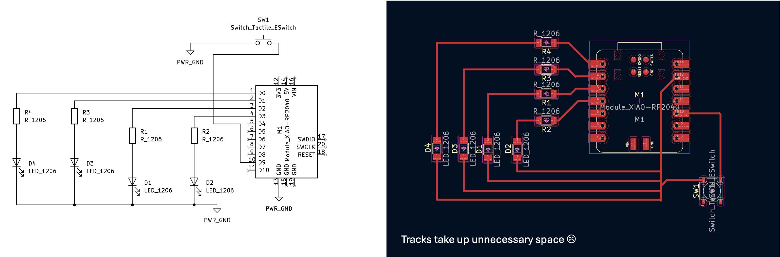
The KiCad is separated into two workspaces that complement each other: Schematic and PCB Board Editor. Schematic is essentially the logic view of your circuit diagram to prepare components and set properties in preparation for the PCB Editor. This phase of the process is not a physical reflection of the PCB layout so the diagram of the components will be shown differently than the physical characteristics of the components (including pin locations). PCB Editor is the physical representation of your board input with copper tracings before export to Gerber files for manufacturing. Note the minimum copper clearance and track width is 0.4mm due to the diameter of the shop’s end mill - this can be changed under Board Setup.
My first iteration was to place all the components as close to the RP2040 as possible, but soon realized the wire traces took up unnecessary space.
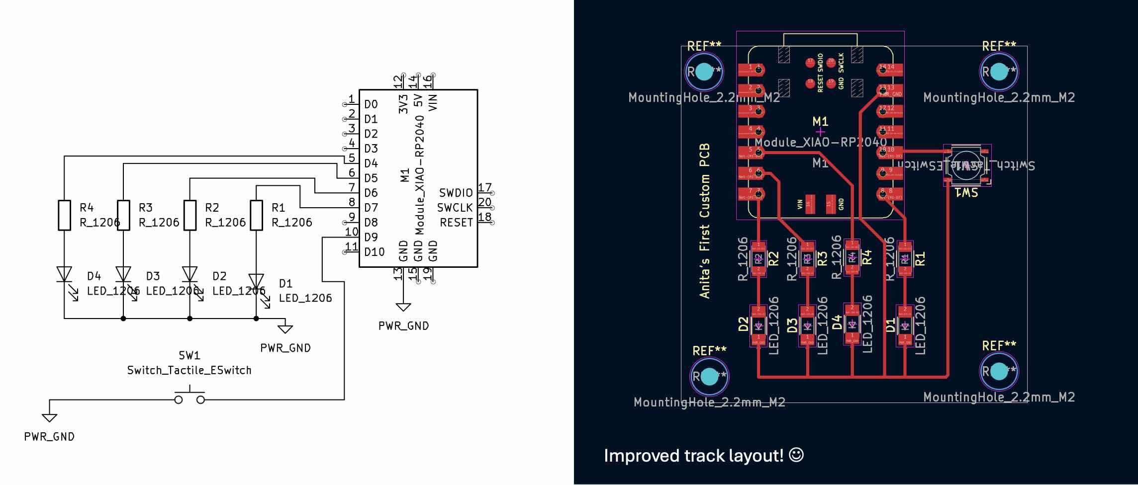
The trace layout was then made more compact by making use of the dead space under the RP2040 for the second iteration.
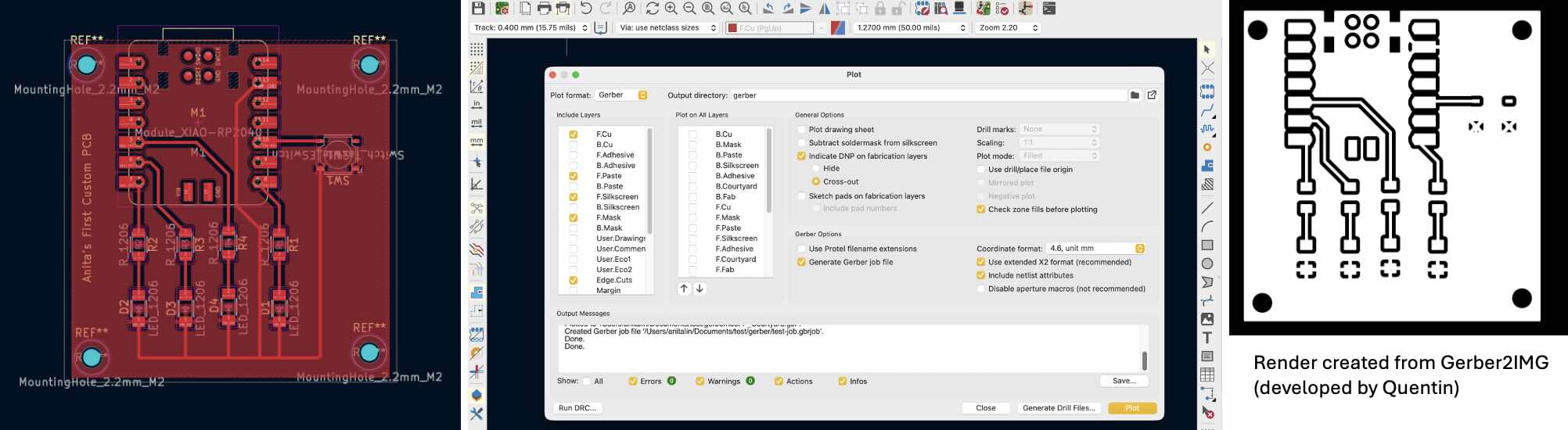
Once all the component are finalized, it was time to export gerber files which is a standard format used in manufacturing to produced PCBs. They are essentially the blueprints that define layers of the PCBs such as drill location, copper layers, board cut outline, and silkscreen (for annotations). We need to convert the gerber file to black and white PNG files (use Quentin's convertor here) to upload files to our own cnc mills in the shop - see week 6 for the machining process.
[Resources]
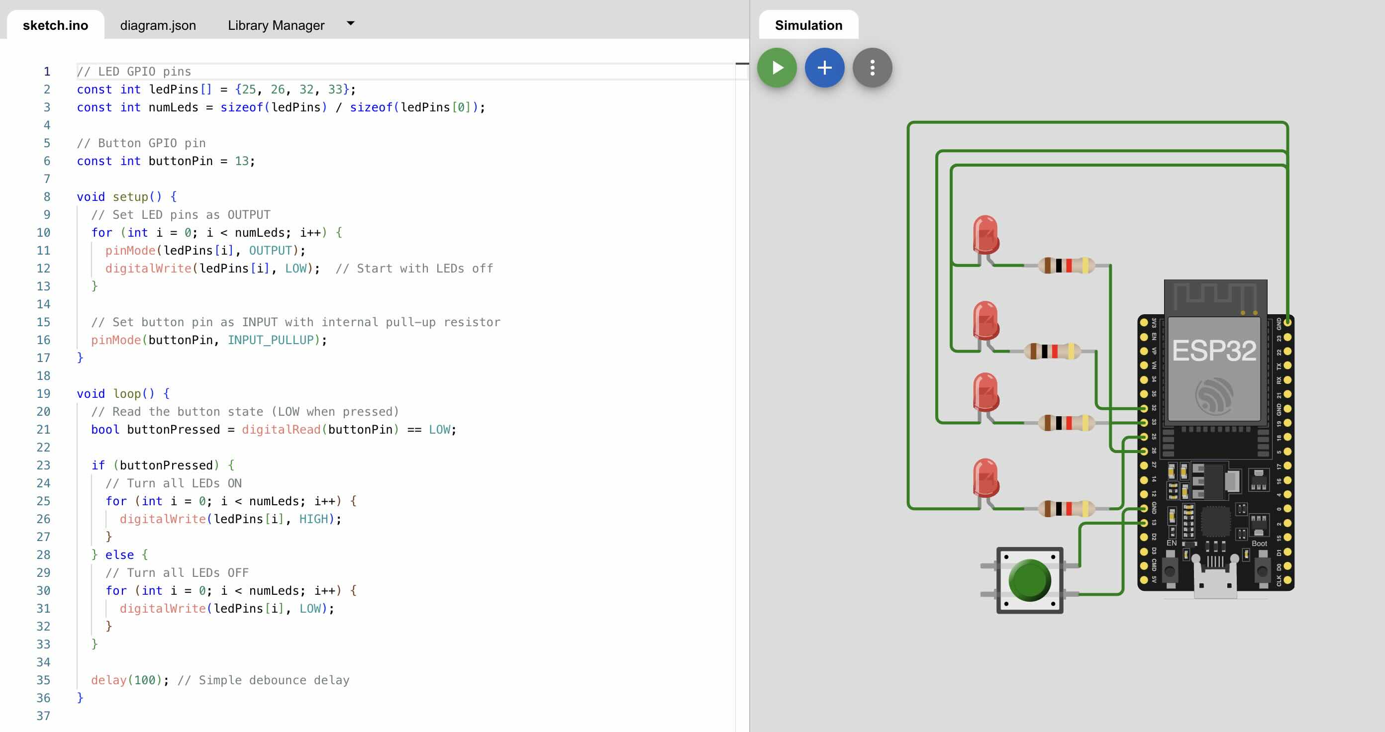
Simulating in Wokwi
This design was briefly simulated in Wokwi (RP20349 replaced with EPS32 in this scenario due to availability) and the code was assisted by Chat. Now that I get the hang of KiCad’s interface, I hope to produce a general use pcb board in an irregular, design specific shape as another exercise in the near future. Perhaps I will do that as I develop my final project with inputs such as distance or touch sensors.
Electronic Measuring Tools
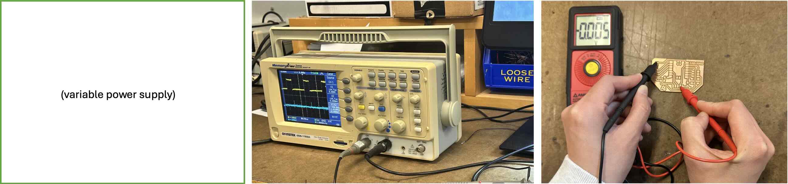
Our TA, Gert, shared a helpful analogy using water pipes when describing the basics of electrical engineering in that voltage is like pressure going through the pipe, current is like the diameter of the pipe, and resistance is any obstructions inside. He walked us through a few useful tools while working with electronics: Variable power supply, multimeter, and oscilloscope. Below is a brief overview of their roles:
• Variable power supply provides a controllable voltage or current to power electronic circuits or devices. Used for testing varying voltage levels in circuits to be mindful of sensitive components that may be at risk of damage
• Multimeter can measure voltage, current, resistance which is useful when checking continuity in wiring and detect power output.
• Oscilloscope is used check voltage change over time thought visualized waveform intervals. Often used to verify digital signals and analyze circuit behaviors.