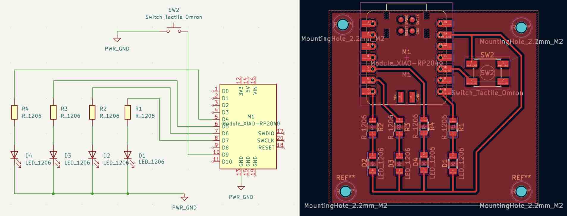
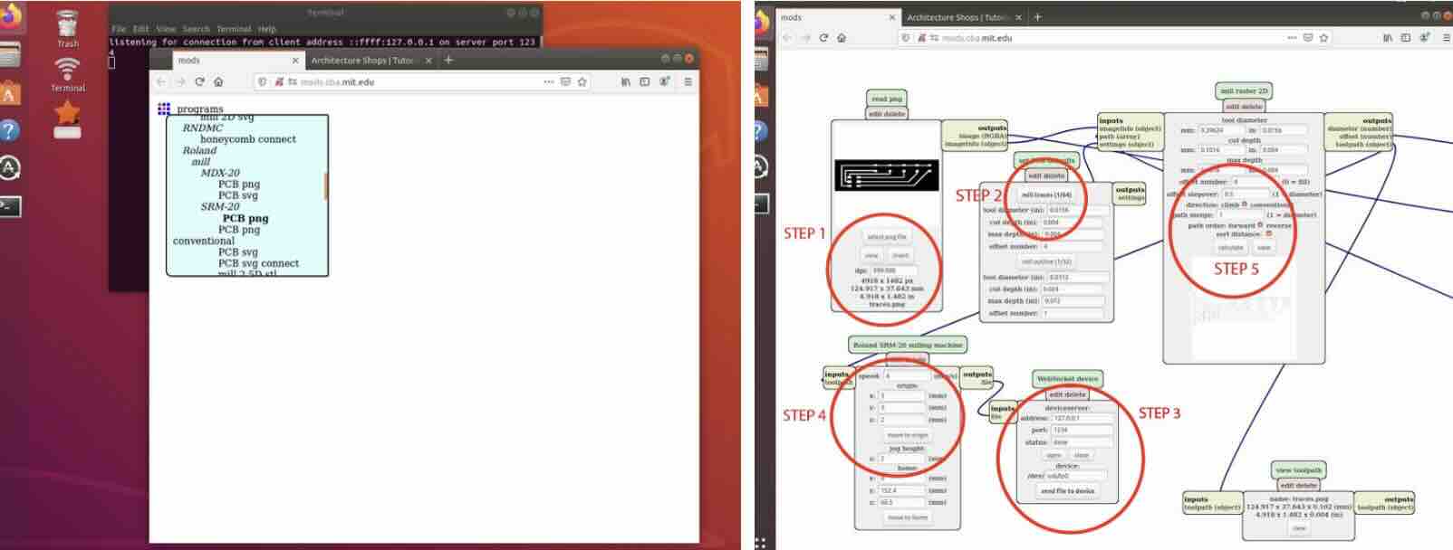
There are two Modelas milling machines in the architecture shop, one is the older model MDX-20 and the other is SRM-20. In this exercise, I used the SRM-20 to produce my very first pcb (woohoo)! Since last week’s exercise, I didn’t change too much for my design aside from updating the tactile switch and a few traces shown below. The goal is to go through the basics of the workflow first.
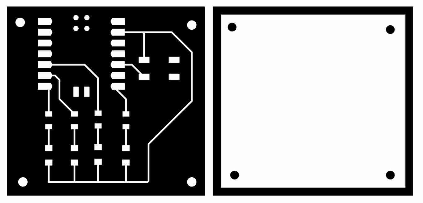
We needed two separate black and white PNG files: One for the traces (to be cut first with 1/64” end mill) and one for the board cut outline (to be cut last with 1/32” end mill). The images can be generated using the gerber2img site.
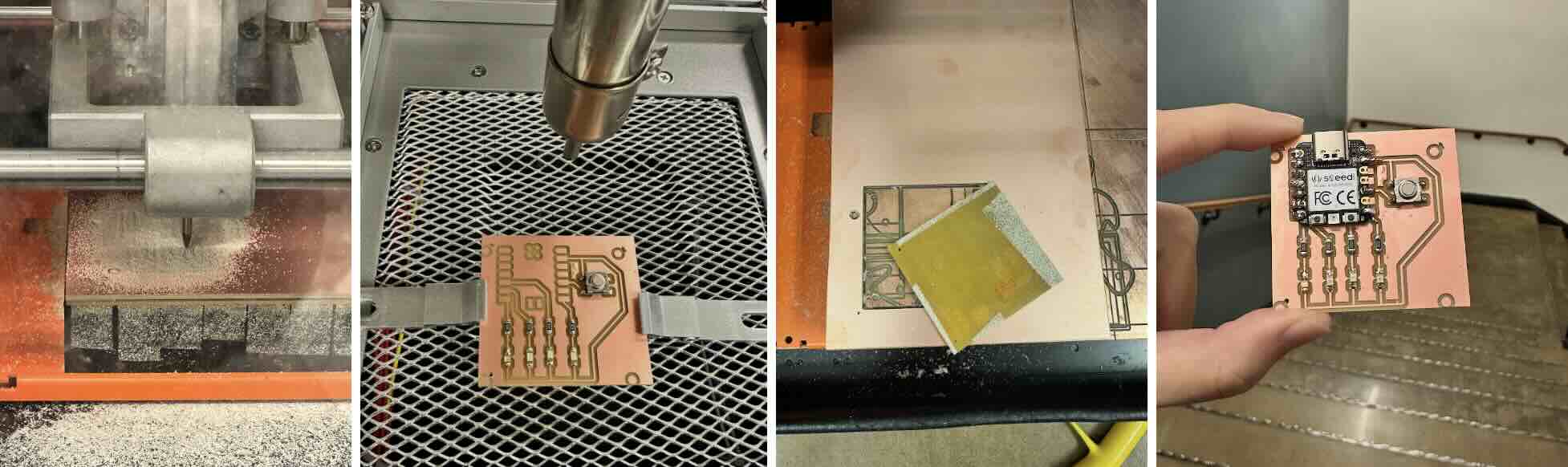
We want to make sure the spoil board on the CNC and the copper material to be as flat as possible (to be double taped down securely). Using the default mods page, the traces were cut first with the 1/64” end mill since you wouldn’t want the board to move around if you were to cut the board outline first. Afterwards the end mill was switched out to 1/32” for the outline.
Some issues faced and observations during the production process were the following:
• Board lifting during milling - My board only measures 2”x2” so during the board outline cut process, my copper was getting lifted by the end mill since I did not have enough tape to secure the area. Need to be more careful next time.
• Drill hole fail - My drill holes were present in both the PNGs so both layers became misaligned while my copper was getting caught by the end mill. Next time I would remove the drill holes from the trace layer and only keep them in the outline layer.
• Machine connection error - Troubleshooting the connection error with the terminal took up the majority time in this exercise. The SRM-20 was acting up all weekend and it resulted in us having to reset the machine every time we had to swap the end mill and upload files in the mod. As of this writing, the general solution was to open the terminal through the mods js folder and enter “node deviceserver.js 127.0.0.1 1234”. Then refresh the mod page > open server program > PCB png before trying to reconnect to the server… and a little prayer won’t hurt 🤡
[Resources]
Embedded Programming
Learning from week 3’s soldering exercise, I was already comfortable using the heat soldering gun (270 deg celsius was the sweet spot) but you must be careful directing the heat in an area for too long since the copper can easily form bubbles underneath.
Based on the four LED’s (blue, orange, yellow, and red), the forward voltage varies between 2V-3.3V so we just need to make sure the Xiao RP2040 pin isn’t overloaded (4-8 mA is the suggested safe limit and 5mA is used here for this Xiao). The GPIO pin provides 3.3V so I went with 100 ohms for a bright output across the board. If I were to do this again, I probably could’ve gone with 1k ohms resistor for less of a blinding experience.
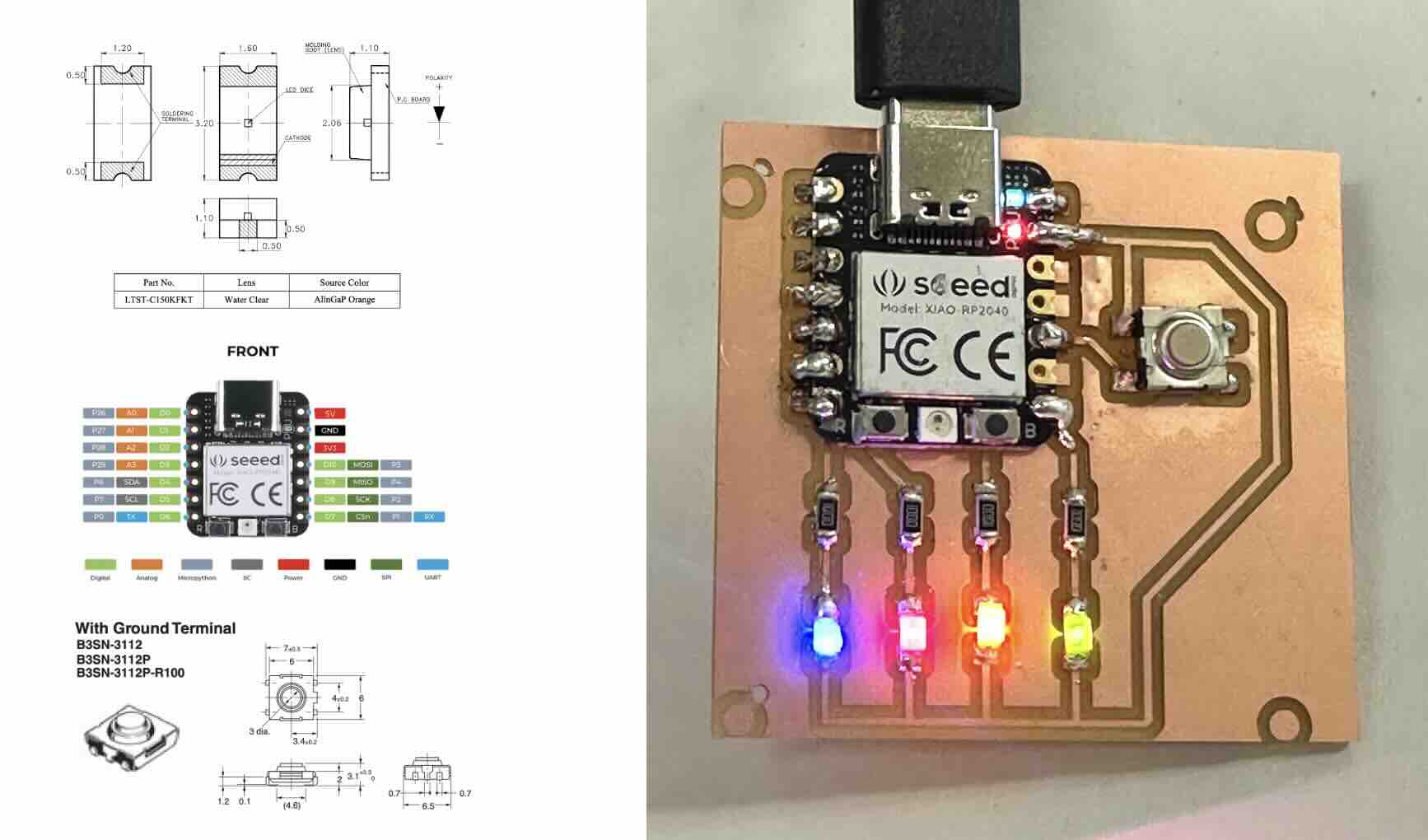
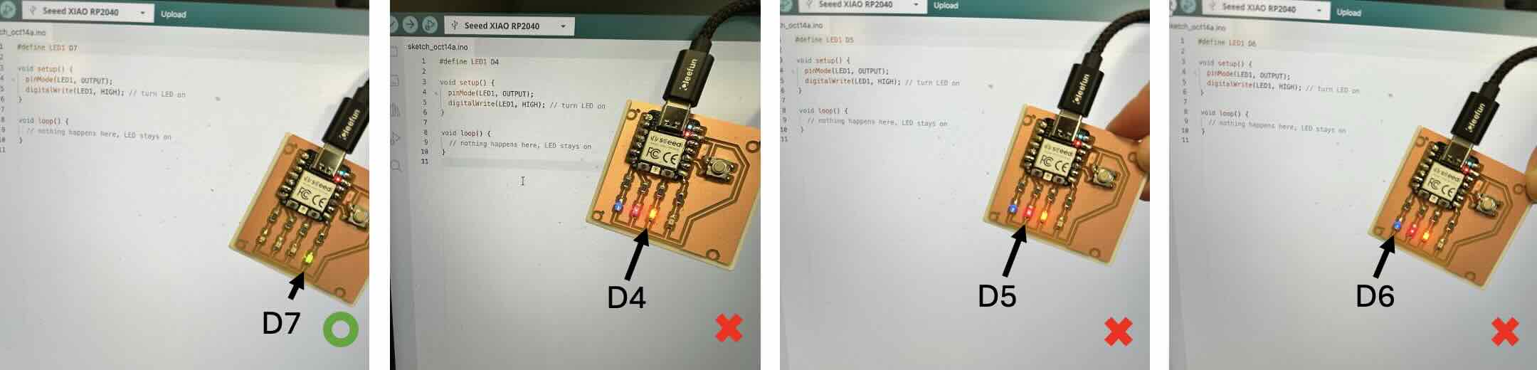
The purpose of this PCB was to simply control the LEDs every time the button is pressed, but getting to this point wasn't an entirely smooth process. Lesson learned (and still learning) is to first check for any shorts under the microscope and minimize cases of accidental solder bridging. Then once the physical traces look good, double check the pin numbers in the code with the RP2040 spec sheet since they are not the same as shown in KiCAD (easy to get confused, for example pin 8 in KiCad is actually D7).
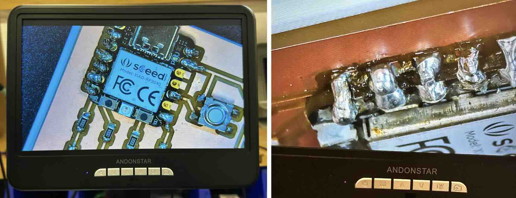
My board currently does not work perfectly with the code that is supposed to run a chase after a press of a button... LEDs are supposed to run right to left in the order of D7, D4, D5, and D6 pins but D4-D6 pins tend to appear all at once together. This may be a hardware issue again since I ran a separate test for each LED to turn on.