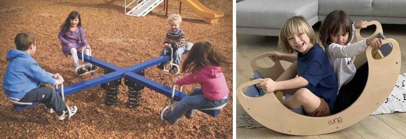
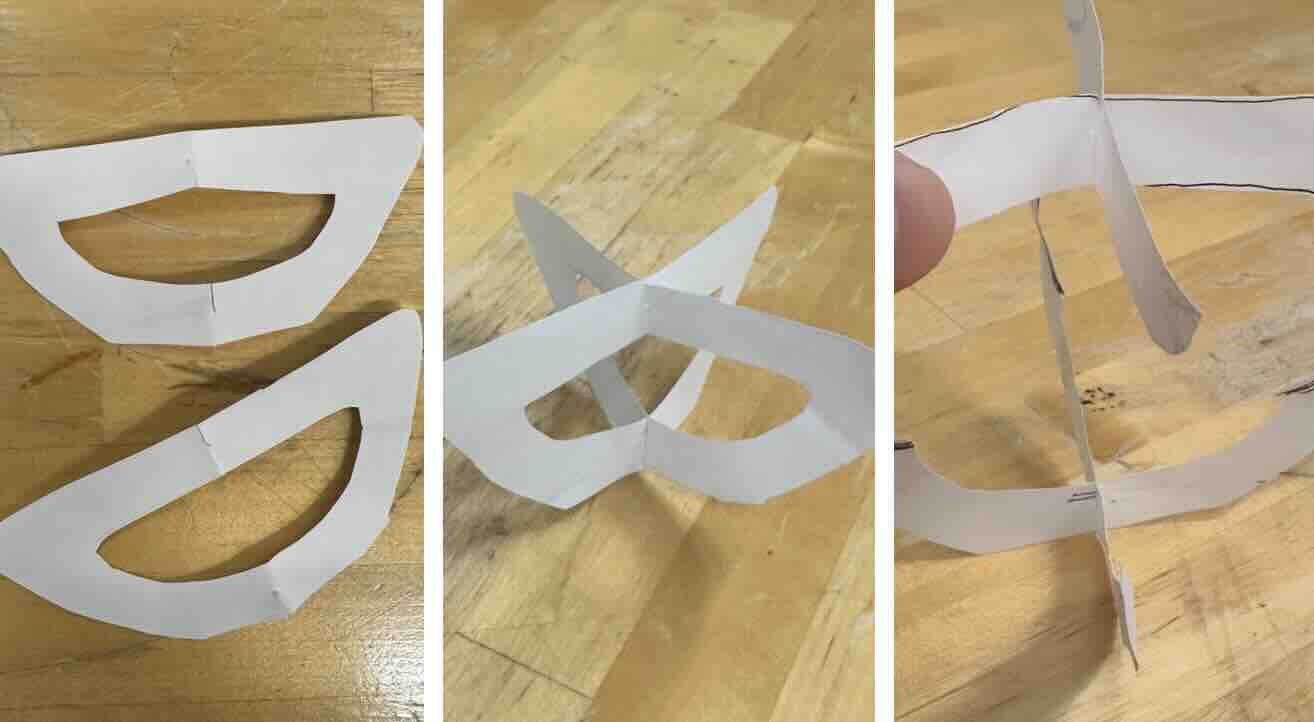
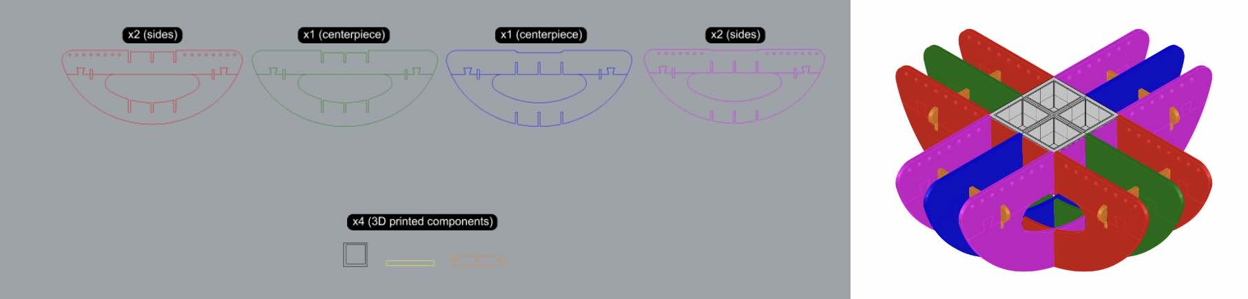
I wanted to create something playful that would bring people together - dedicated to my fellow yappers in the studio. I kept thinking back to my childhood memories on the seesaw and took inspiration from children’s rocker toys. Instead of sticking with the usual two-seater, I decided to push myself and make a four-seater version. I shaped it like a half dome to allow for a wider range of movement while easing the stress on the OSB material. I started with a quick paper model to understand the form and sequence, then refined it in Rhino. That’s when I realized the structure needed to be split into top and bottom sections to maintain design symmetry during assembly.
Design Development & Machining
We were limited to using 4x8-foot OSB (oriented strand board), an engineered wood panel composed of compressed wood chips bonded with adhesives. OSB is a cost-effective alternative to plywood for prototyping large-scale models, though it is more susceptible to chipping and fracture under stress. To accommodate these material characteristics, I used a 0.45 inch joint width (matching the average thickness of the OSB) and omitted tolerance adjustments, as the material’s flexibility could accommodate minor variations. I also ensured adequate spacing throughout the design to maintain overall structural stability during assembly.
Typically, seating dimensions are at least 18 inches in both width and depth, with a height of at least 18 inches above the ground to ensure comfort. However, due to material limitations, the seats in this prototype were reduced to 12 inches in width and depth, and 16 inches in height at the neutral point. As a result, this model functions more as a half-scale prototype for adult use and a full-scale version suitable for children.
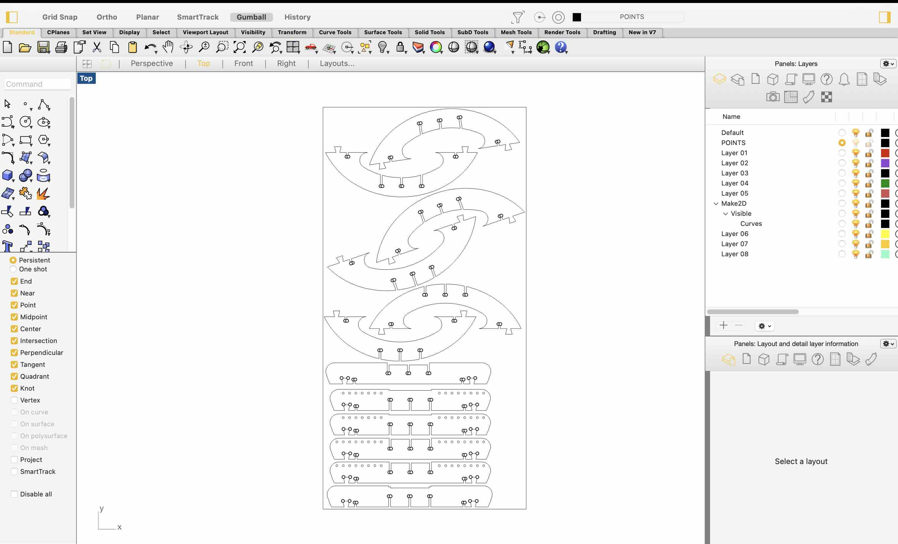
Note that this workflow applies specifically to the Architecture Shop’s CNC machine in the N51 building; procedures may vary in other shops. Chris guided us through the general process of preparing files for the Onsrud CNC router. The first step involves laying out all components as 2D linework composed of closed polylines. A common practice is to add dogbones, small drilled relief cuts at sharp interior corners. Since CNC end mills produce rounded corners, these dogbones allow joinery pieces to fit properly without interference.
In Rhino, I organized the dogbone points on a separate layer and verified that all components fit within the material board dimensions before exporting the file in a compatible format (.dwg, .dxf, or .3dm). The shop monitors then imported the file into Mastercam to generate toolpaths for CNC milling. Here, I learned the importance of vector direction in defining accurate toolpaths. The orientation of line vectors determines whether the CNC cuts along the inside or outside of a contour. For instance, perimeter cuts require the end mill to follow vectors moving clockwise so that the bit mills along the outer edge of the geometry, preserving the intended dimensions of the piece. When cutting holes or interior profiles, the toolpath should follow counterclockwise vectors, ensuring the bit removes material from the inside edge. Maintaining correct vector direction prevents dimensional errors and ensures a cleaner process on the machine.
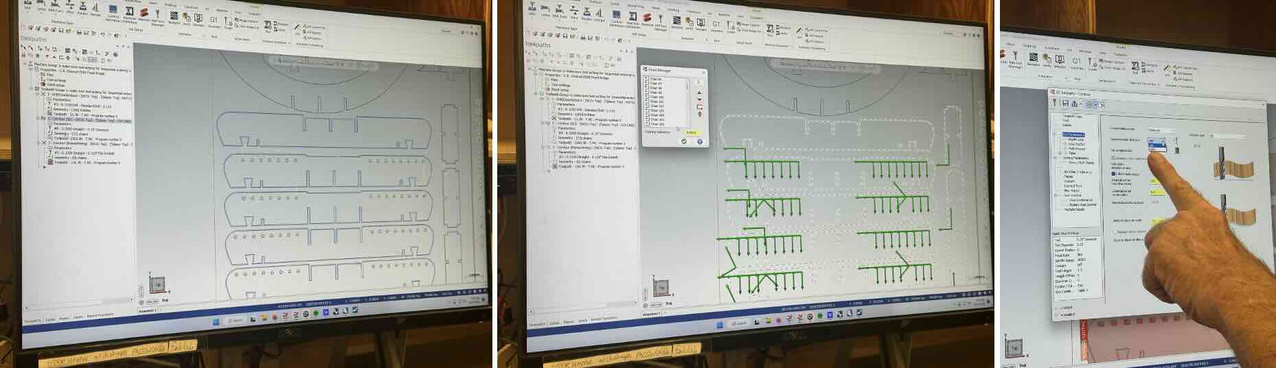
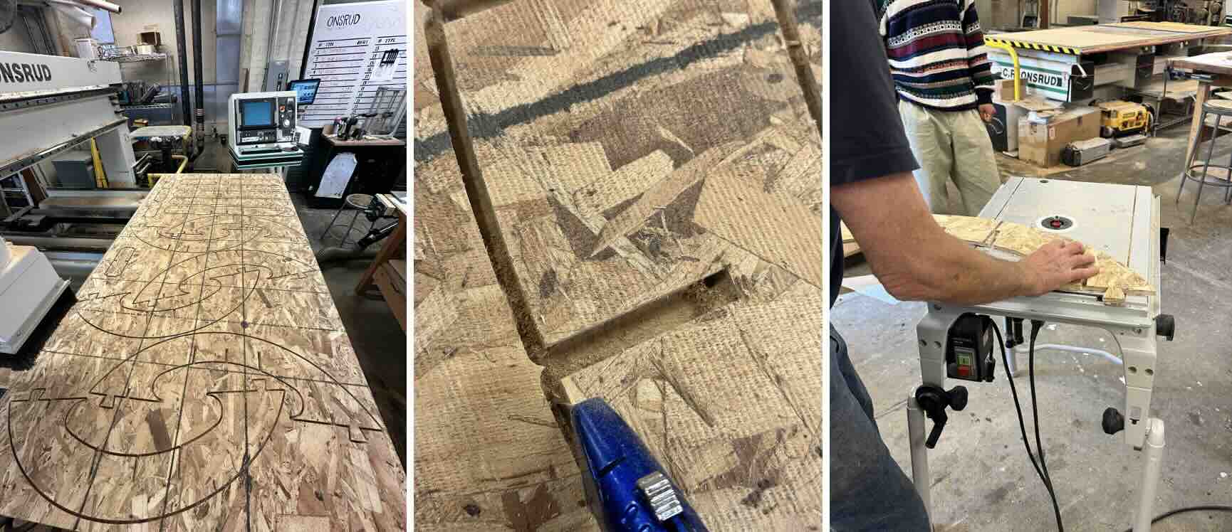
Although the Onsrud’s vacuum bed helps secure the material during cutting, onion layers - thin, uncut layers of material left intentionally - are typically added in Mastercam to prevent parts from shifting. While effective, this makes post-processing more time-consuming. After removing the pieces and collecting a few splinters along the way, I used a router to ease the edges for a smoother finish.
Assembly
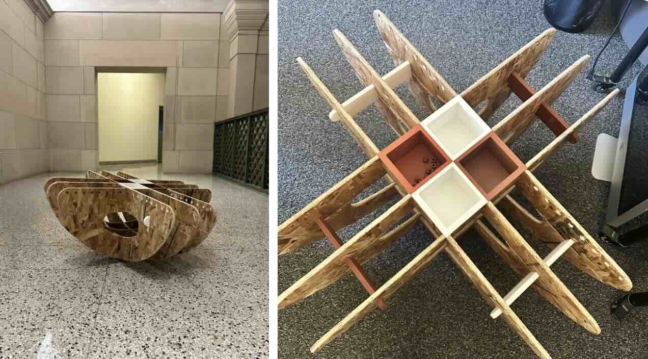
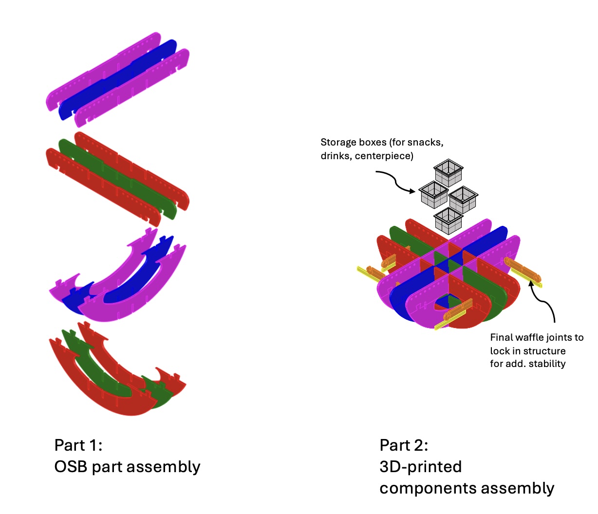
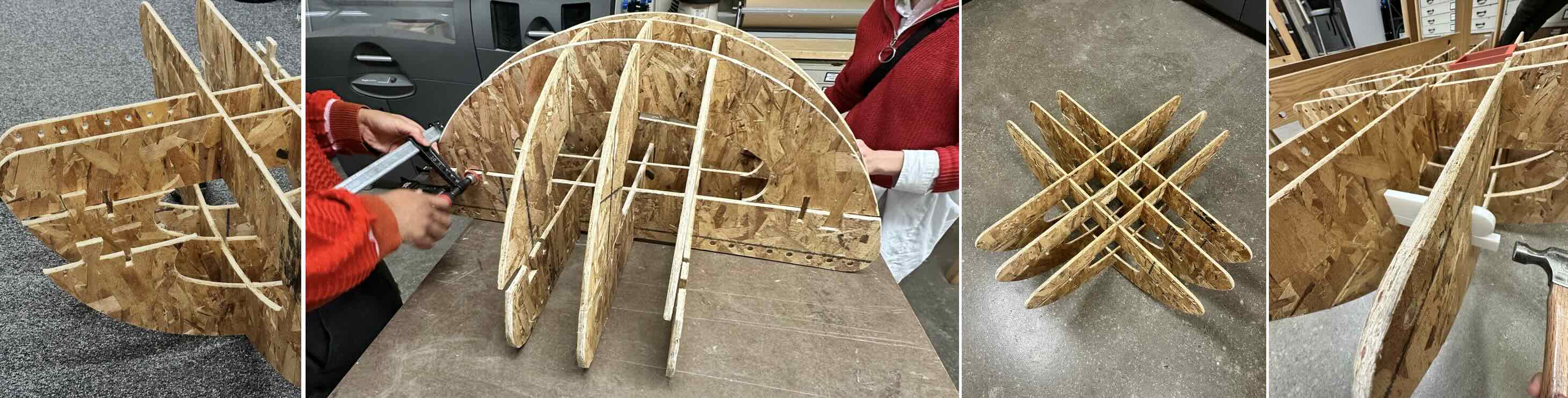
The assembly process proved to be the most challenging stage, as I had to manage the x, y, and z axes simultaneously when aligning the joints. The structure combined box joints and dovetails to connect the top and bottom curved sections, requiring careful coordination. The waffle structure had to be partially assembled first, then gently hammered together piece by piece to ensure each joint met precisely.
At one point, my architecture friends Clara and Jordan walked by the student lounge and saw me struggling to fit a particularly tight dovetail joint. Jordan, who had prior experience as a millworker, advised against sanding the joints since that could loosen the fit too much. Instead, we brought the structure to the woodshop and used clamps in pairs to gradually press the top and bottom sections into place - an approach that worked perfectly to create a tight joint.
For additional reinforcement, I 3D printed several remaining components to lock the four seat sections in place. This provided a more secure fit and avoided the risk of damaging the OSB material, which can easily chip or shred when hammering linear pieces through. The hybrid use of CNC-milled OSB and 3D-printed connectors allowed for both structural stability and ease of assembly.
This experience was not only technically rewarding but also heartwarming. Their willingness to jump in and help turned what could have been a frustrating evening into a memorable moment of collaboration. It reminded me that so much of making (especially here at MIT) is rooted in community support. Sometimes things can’t be done alone (and more fun with friends).