Definitely a scarier week -- never have I ever designed a PCB board.
However, it did bring me back to high school electronics class, and generally being excited about circuit boards.
There's something oddly satisfying and similar to architectur plan layout and PCB board layout:
Plans - the Layout. Sections - the many layers of the PCB board. 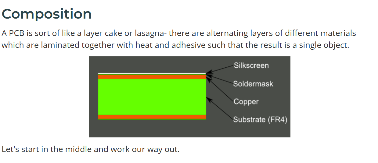 credit: SparkFun Electronics
Never did I know before that PCB could be multilayered with 0 ohm resistors serving as bridges over and under wirings.
I also had to read up on a lot of terms, since Ohms, Resistors, Capacitors and MOSFETS are greek to me.
SparkFun electronics was my unofficial hero this week: How to Read a PCB Schematic.
Seconded by Anthony's Vimeo tutorial of creating a Fusion tutorial for electronics design: Fusion Schematic Setup
I had a big AHA moment when everything in the surrounding board connected to GRND.

Bad Board:
This is as far as I got:
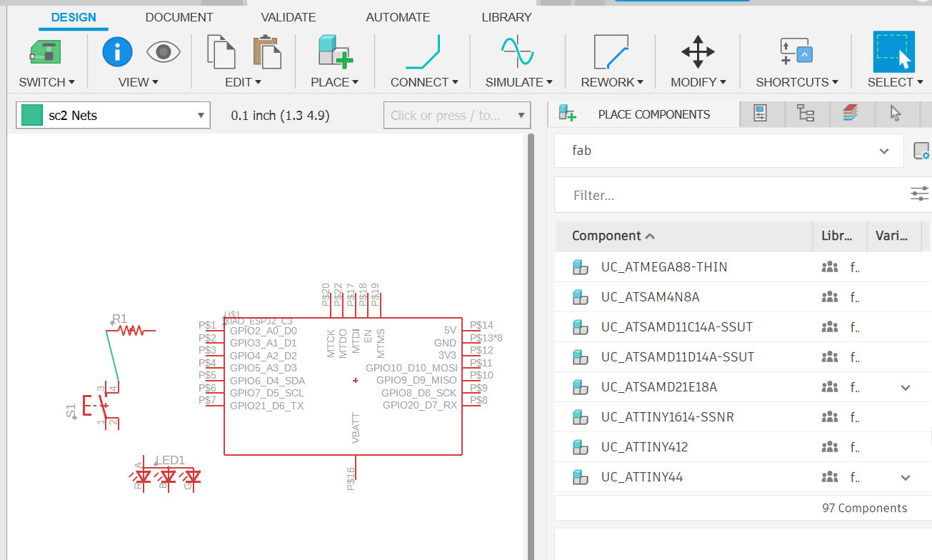
I used Fusion software. I tried adding the components that I could follow along with the video.
I upgraded to the Xiao C-3 board since it has wifi capabilities towards my final project.
I got stuck in the part where I needed to add pins for future iterations and will need to revisit before fabrication this upcoming week.
However: for my final project, I'm looking to create a board with a motion sensors which triggers on a light that gradually gets brighter, in lieau of the 2001 Space Odyssey sequence. I consulted ChatGPT on this, with the following prompt:
need to design a circuit so that motion sensor activates an LED light that grows gradually brighter (warm yellow).
The components I'm assuming I'll need:
Xiao C-3
Motion sensor hardware
Resister
Chat's Response:
Seeed XIAO ESP32-C3 (PWM + logic)
PIR header (3-pin: VCC, OUT, GND)
N-MOSFET logic-level, e.g., AO3400A (LED switch)
LED header (2-pin to LED/LED strip)
Supply header (5–12 V in, see notes)
Resistors: 100 Ω (gate stopper), 100 kΩ (gate pull-down)
Caps: 0.1 µF near XIAO, 10 µF on VIN
I'll have to decode this next week. Good luck.