This week started with some final debugging of the board design from last week.
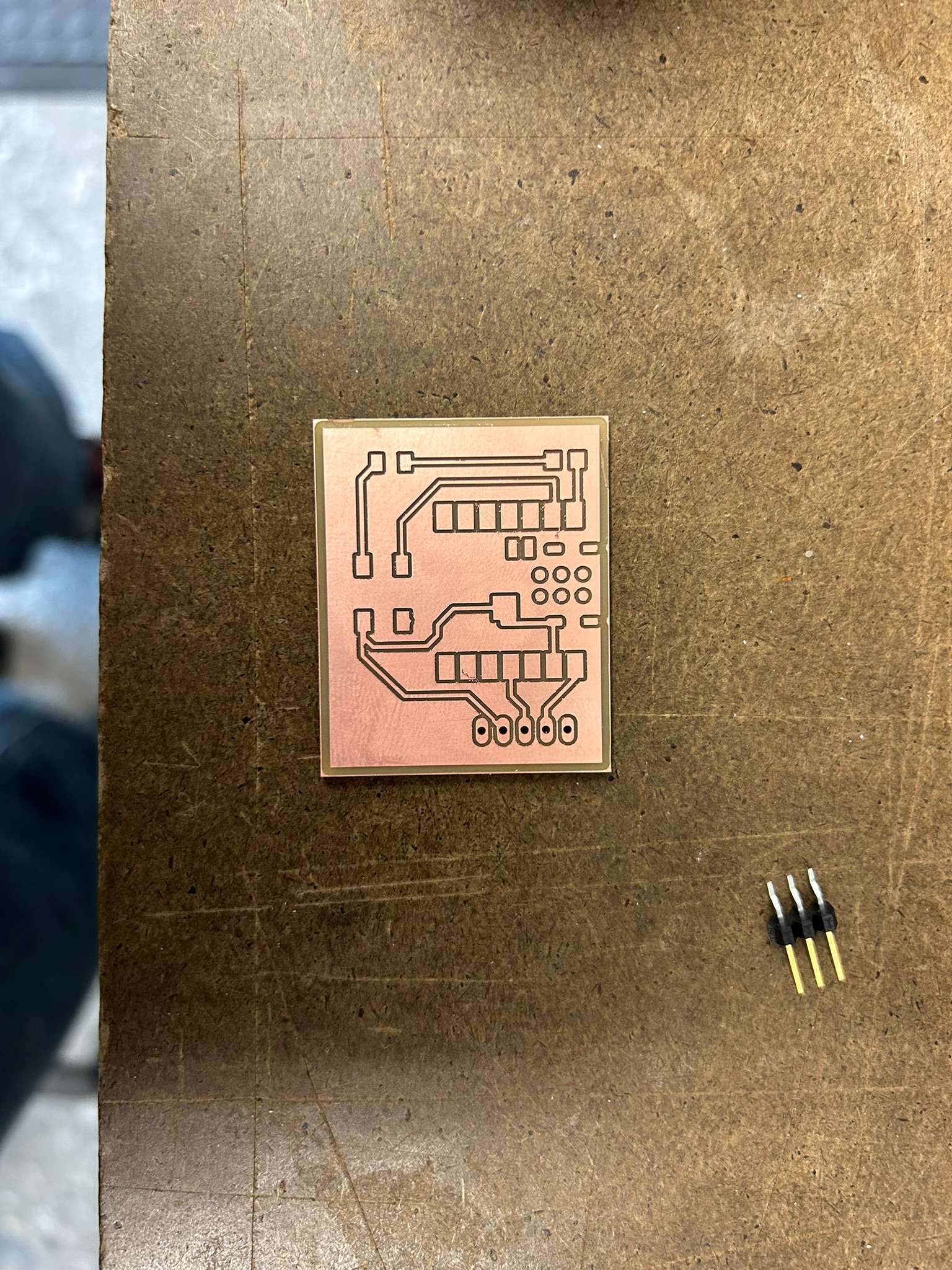
Via office hours with Anthony, I learned I needed an input/outpout device called the PIR that comes only later in the semester.
This component has a very simple data sheet, with 5 pins of which 3 were important leading to 3V3, GND, VIN.
I learned:
1. Fusion is not user friendly, I'm switching to KiCad.
2. Utilize a polygon to create double outlines for all your boards. This is super critical otherwise the SAM-20 router will mill everyting outside your components which is not very economic.
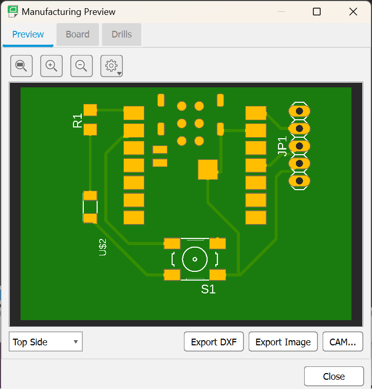
3. Issue with export: I had to a 'template' when exporting for a single layer board (default).
4. I could not understand where my 'drill' files were. They're in the same 'CAD Outmod' file, one folder location up. Important!
5. Export: via img2Gerber which is a beautiful tool developed at cba.
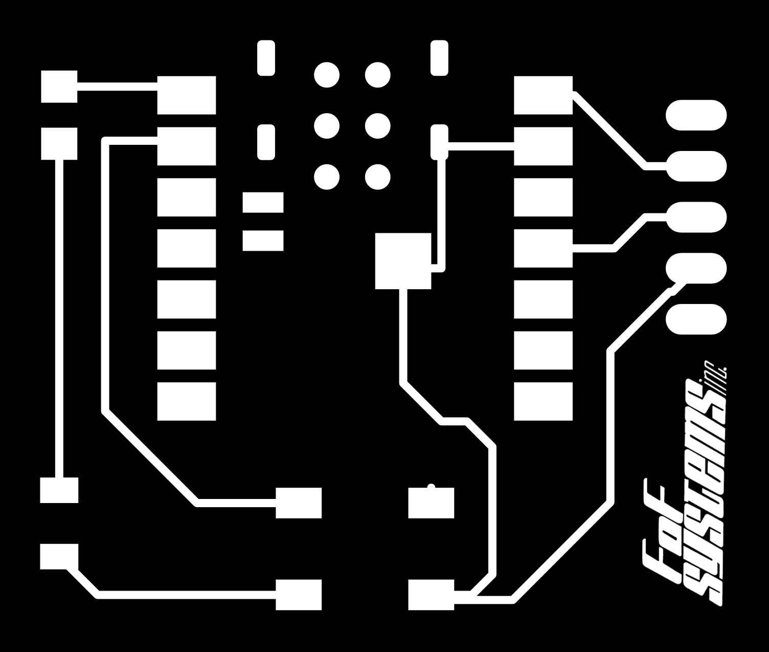
*I thought I was being clever, and I brought my image to photoshop and added a logo. However, I exported in the wrong dpi and canvas size, and this really messed up the milling job. Never play with an img2Gerber file... (unless you know what you're doing). It was a very fun logo....
The exported images had another important anecdote: when you upload a first image, it's critical to lock the proportions/size/location of the image for the future ones (to synchronize). Then you drag and drop both the border file and the drill holes at the same time. This was critical for aligning the pieces to the same exact location, otherwise they'd jump around of each other on the board..
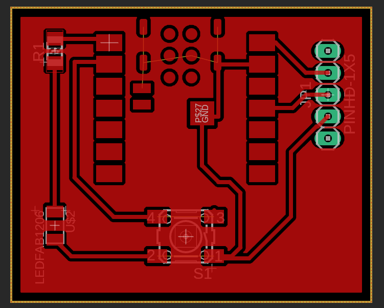
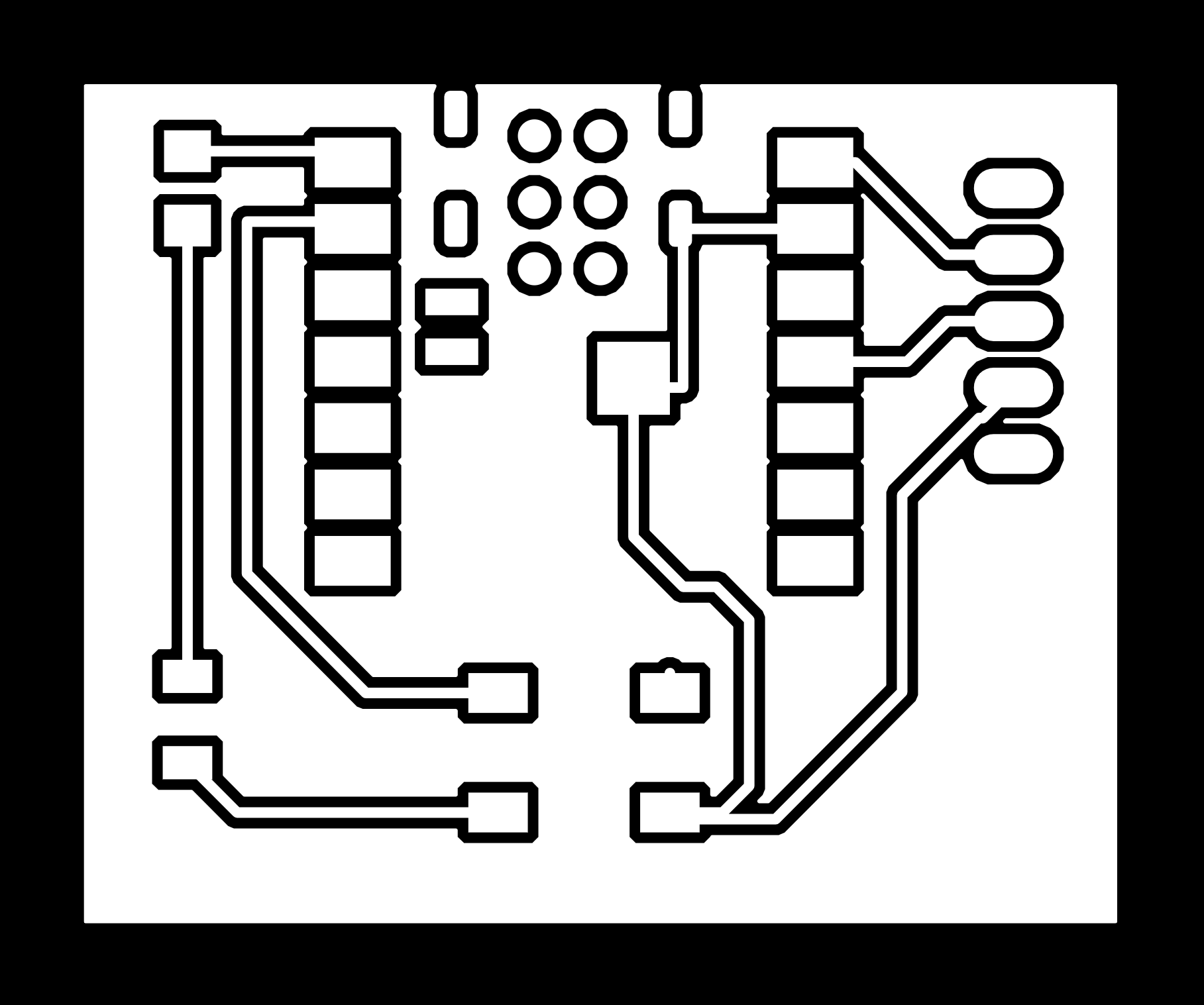
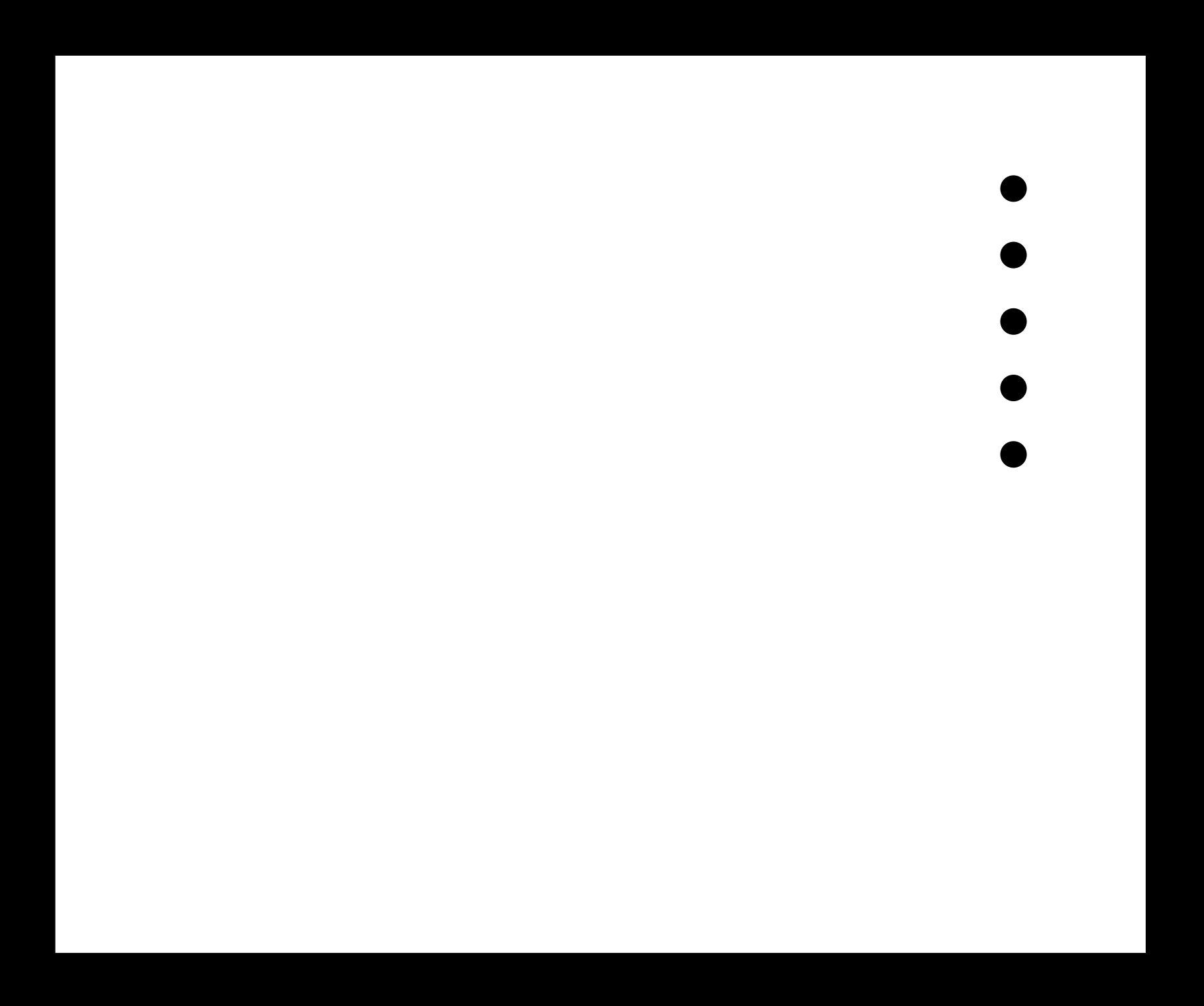
This is what the gerber images looked like before upload (pngs!).
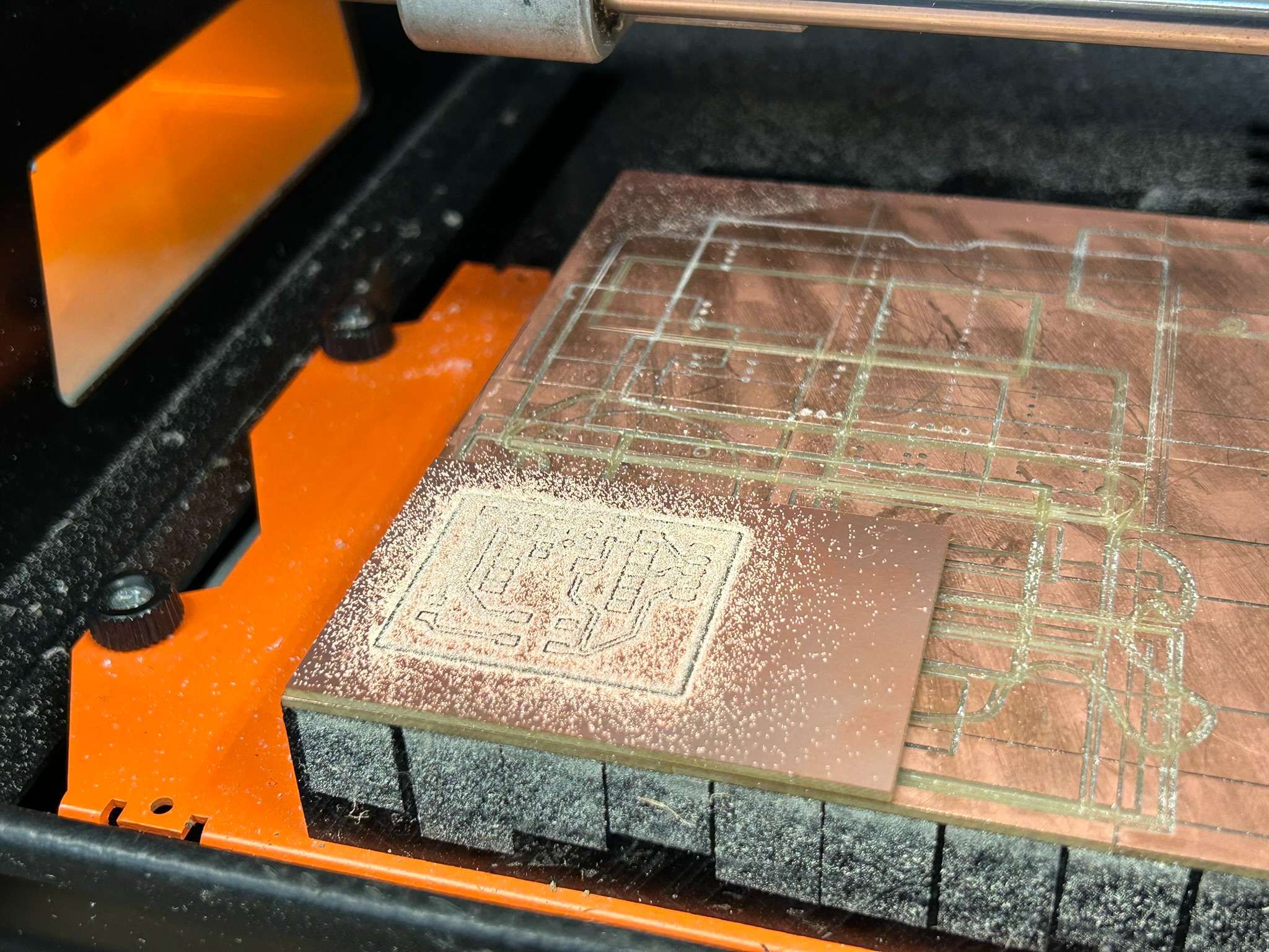
Milling the PCB Board
The milling on the machine works similar to the Vinyl cutter. It was actually super useful to have already done the vinyl, which made this task less daunting.
The machine in questino is a SRAM-20. It is a clunky but single purpose machine which makes it easy (but finnicky) to use.
For starters, the SRAM always has a blinking yellow light that constant requires a machine reboot.
Secondly, the terminal kept getting disconnected. The workaround for that is found here.
Issues and Fixes:
Critical to remember: dpi ~999/1000
1/64" bit for milling br
1/32" bit for milling outlines and drill holes
Calculate! generates the path
Origing: should be kept the same (!) a roughly 5,5,3.
I received help from Gert and Ryan, as we basically kept turning the printer on and off again, and setting up the terminal (instructions on how to on the HTMAA page. )
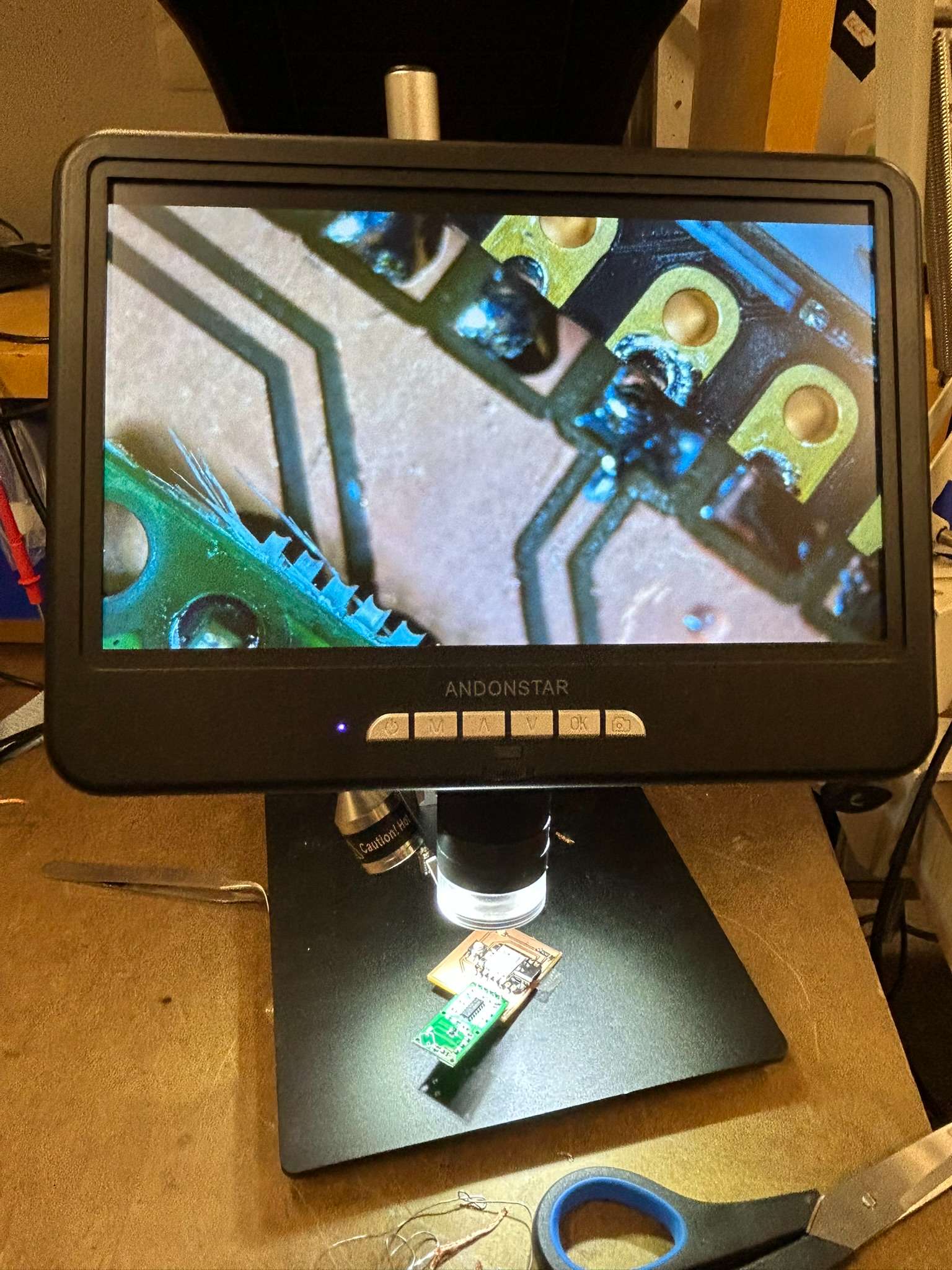
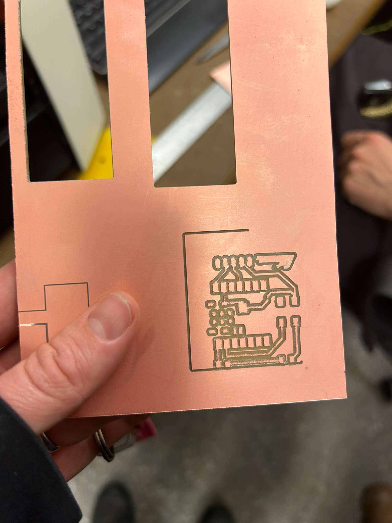
Finally, the printer decided to cooperate and I milled the 1/64" followed by the 1/32".
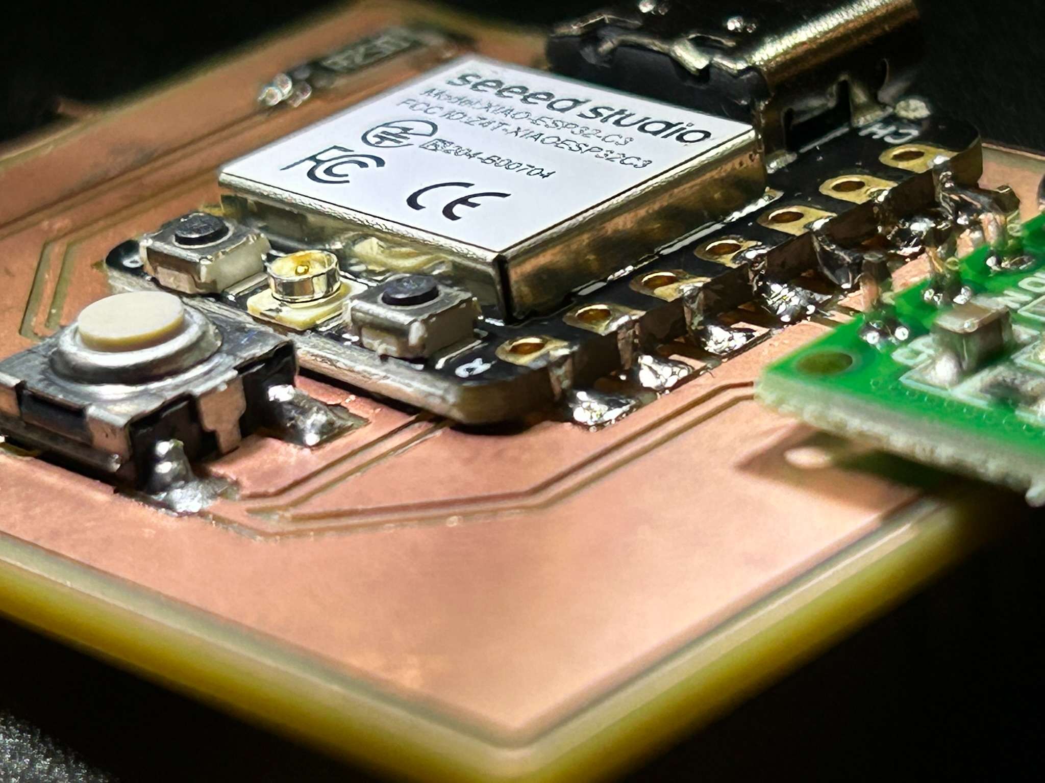
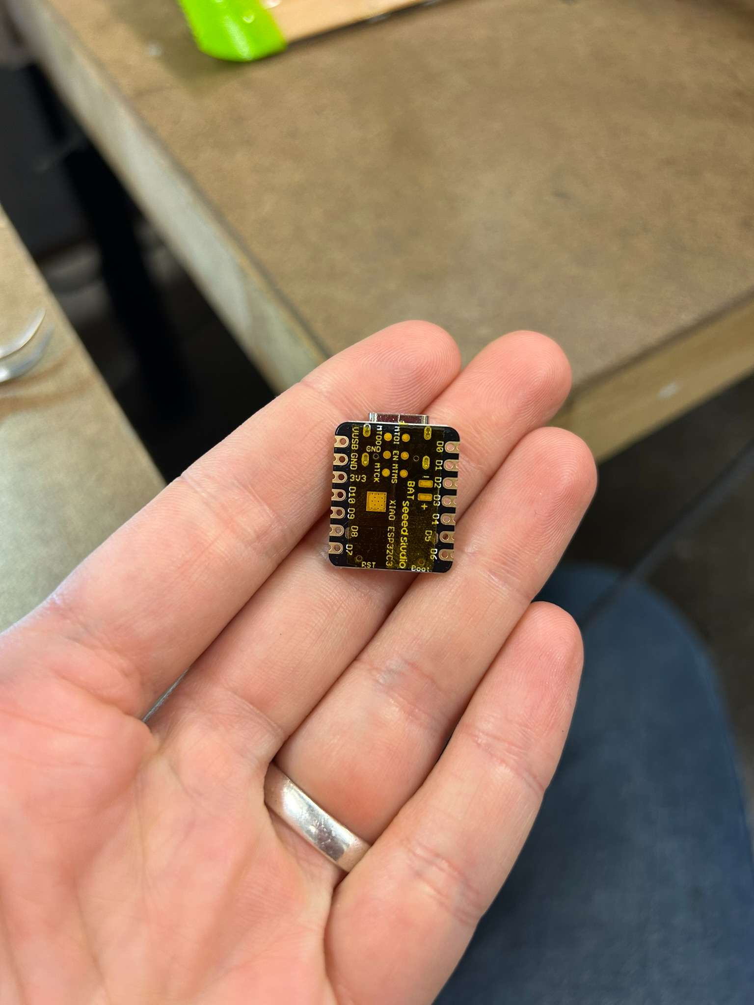
I started by soldering the Xiao C3 and as I went down the line, the component shifted and misaligned. It took me 30 minutes to try and take off the solder, to little avail. After much play, I believe I managed to solder on a slight skew managing to not connect the circuits on the board.. lots of architecture finite modeling helped with this.
I then had an issue with the resistor, which was too large for its footprint. It may or may not short circuit, as it touches the larger polygon. However, since I taped the bottom of the C3 it should not be connected to GND, so hypothetically it should still work.