Project Overview
This week I created a project using computer-controlled machining. The first attempt was a Buddha contour created using photogrammetry and computer-controlled machining. I started with a photogrammetry scan of a Buddha statue, cleaned it up using Maya, then used a Fusion 3D slicer program to generate internal intersections and create the contour profile. The final design was exported as DXF and brought into Fusion as sketches for CNC milling setup and simulation.
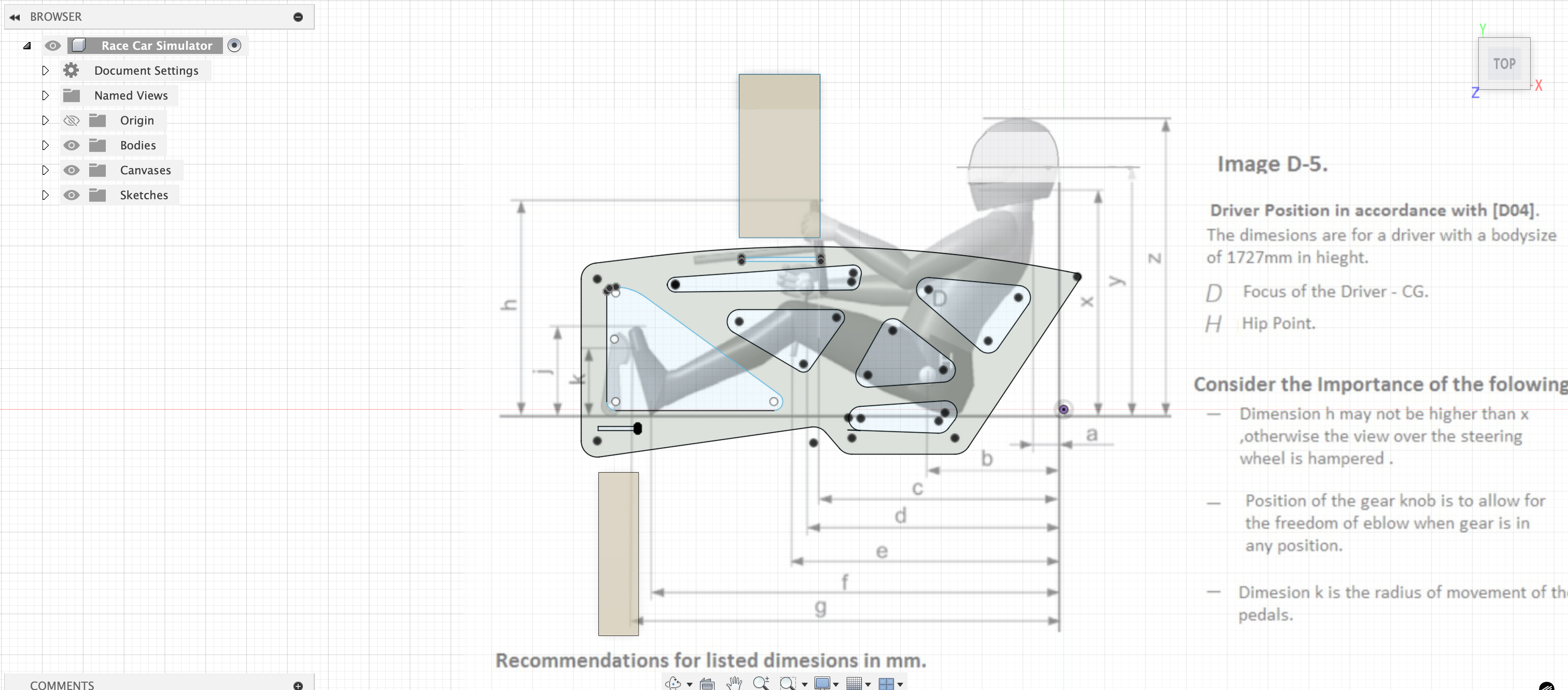
The Buddha cut was too ambitious and the resulting tool path was too refined with many potential issues. So in the following week, I made a racing sim side panel, which followed the same computer-controlled machining procedure. This functional component required precise contour cutting using the quarter-inch end mill to create the side panel profile for a racing simulator setup. This was a much simpler and usable project.
The Buddha cut was too ambitious and the resulting tool path was too refined with many potential issues. So in the following week, I made a racing sim side panel, which followed the same computer-controlled machining procedure. This functional component required precise contour cutting using the quarter-inch end mill to create the side panel profile for a racing simulator setup. This was a much simpler and usable project.
Photogrammetry and 3D Processing
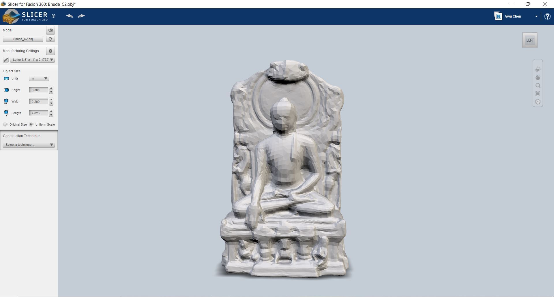
The project began with a photogrammetry scan of a Buddha statue, capturing the intricate details and form. I then imported this scan into Maya for cleanup and optimization, removing noise and artifacts from the photogrammetry process. The cleaned 3D model was then processed through a Fusion 3D slicer program to generate internal intersections that would create the contour profile for CNC machining.
Contour Generation and CAD Integration
The Fusion 3D slicer program was used to generate the internal intersections that would create the Buddha contour profile. This process involved slicing the 3D model at specific intervals to create a series of contours that would define the cutout shape. The resulting contour data was exported as DXF files and then imported into Fusion 360 as sketches, where I could set up the milling operations and generate toolpaths for the CNC machine.
CAM Setup and Simulation
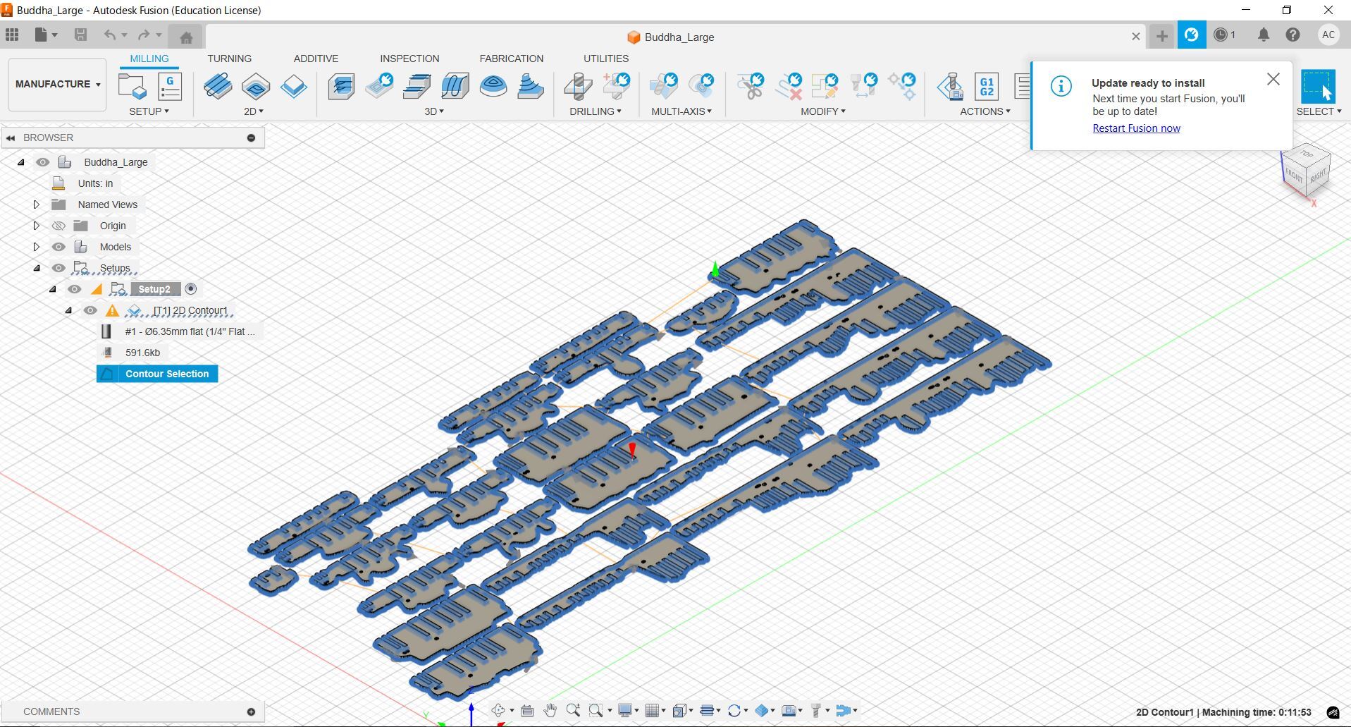
Once the Buddha contour sketches were imported into Fusion 360, I set up the milling operations using Fusion's CAM module. This involved selecting appropriate tools for the contour cutting, setting up speeds and feeds, and generating toolpaths that would follow the Buddha profile. I ran simulations to verify the toolpaths and ensure the cutting operations would produce the desired result without collisions or other issues.
Images
Photogrammetry and 3D Processing
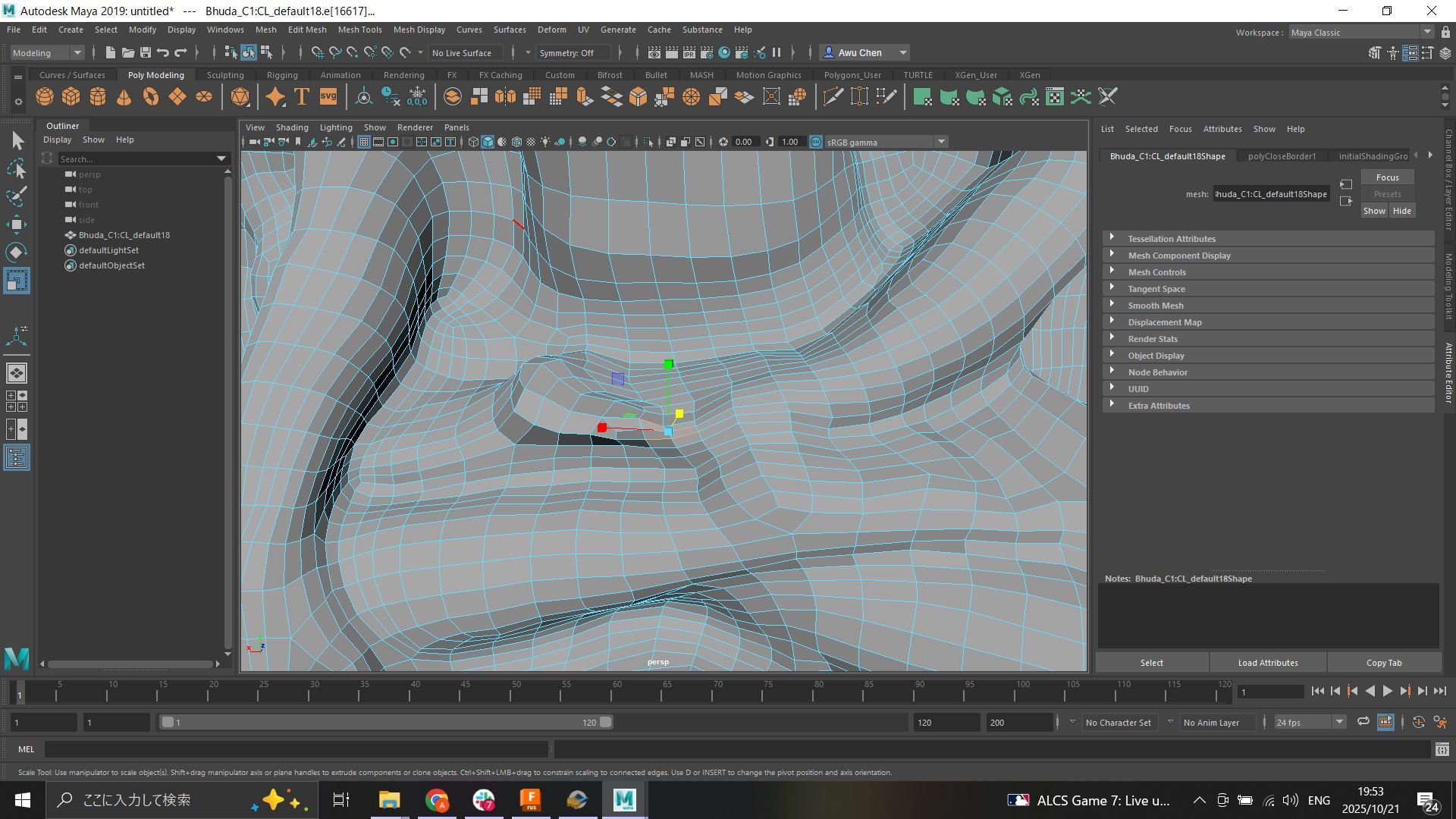
Cleaning up the photogrammetry scan of the Buddha statue in Maya, removing noise and artifacts from the scanning process
3D Slicing and Contour Generation
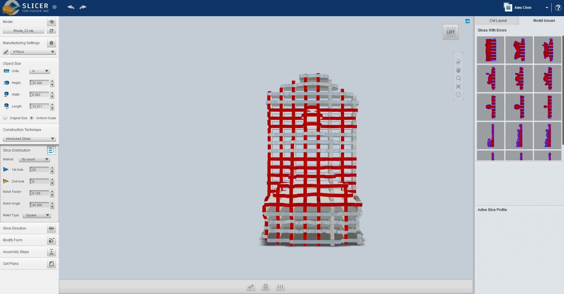
Using Fusion 3D slicer program to generate internal intersections and create the Buddha contour profile
Detailed view of the slicing process showing top and bottom contours of the Buddha profile
Contour Profile and CAD Integration
Final Buddha contour profile generated from the 3D slicing process, ready for DXF export and CNC machining
Fusion 360 CAM Design
Fusion 360 CAM setup and design configuration before actual milling begins, showing toolpaths and machining parameters
Racing Sim Side Panel Project
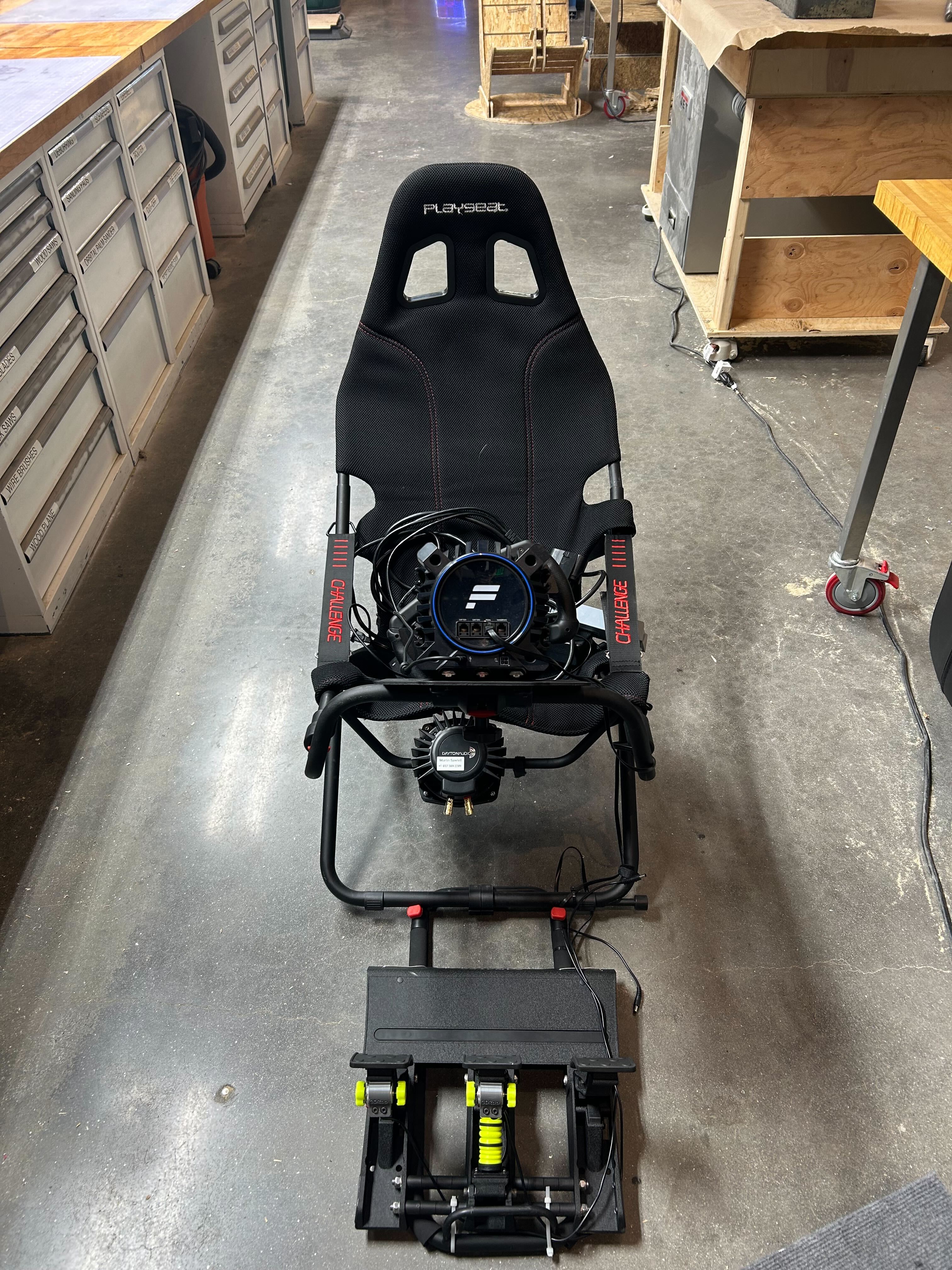
Racing sim side panel material before machining, prepared for CNC milling
Installing the quarter-inch tool in preparation for machining the racing sim side panel

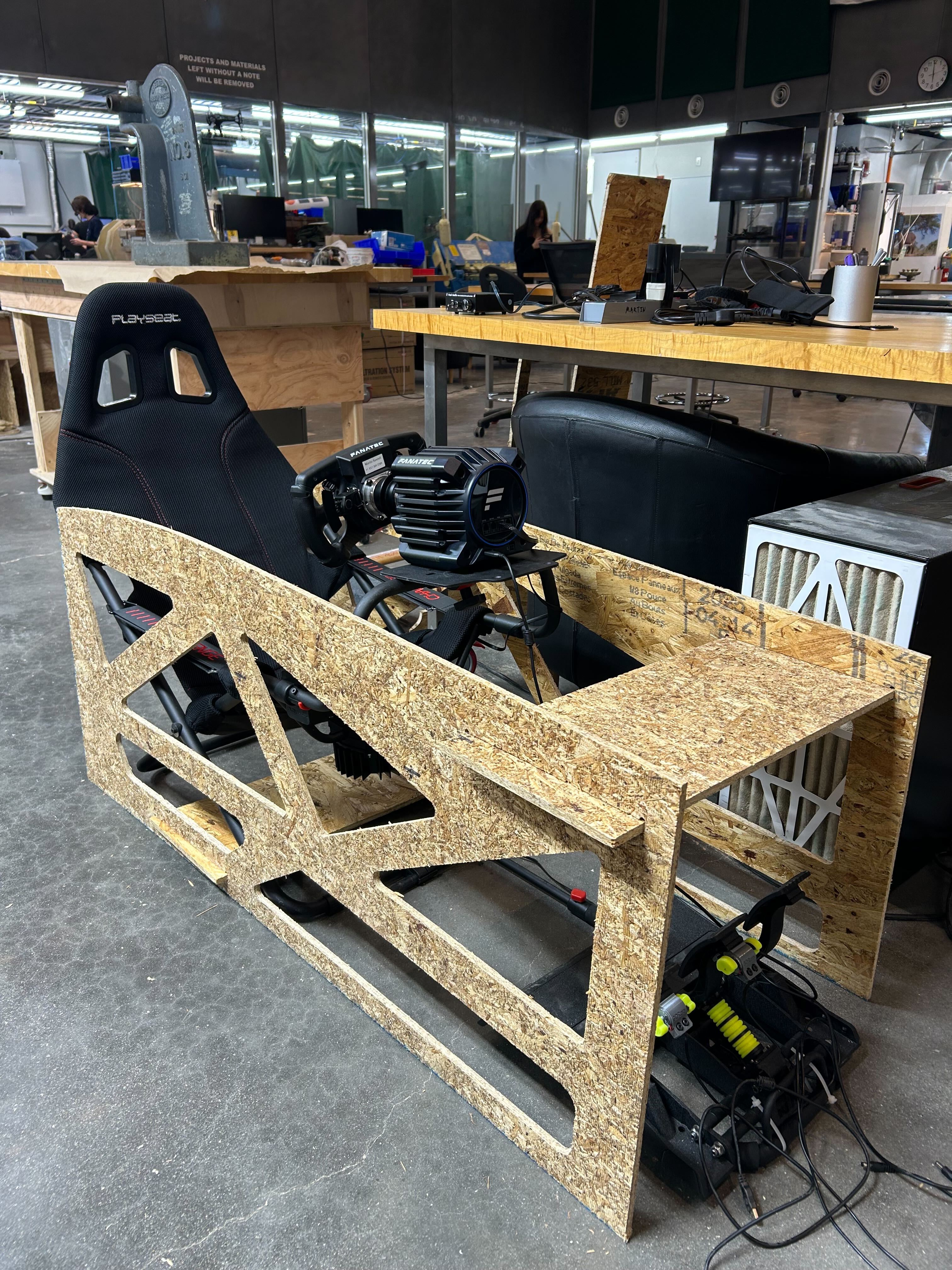
Racing sim side panel after CNC milling, showing the completed cutout profile
Completed racing sim side panel in portrait orientation, showing the final machined result
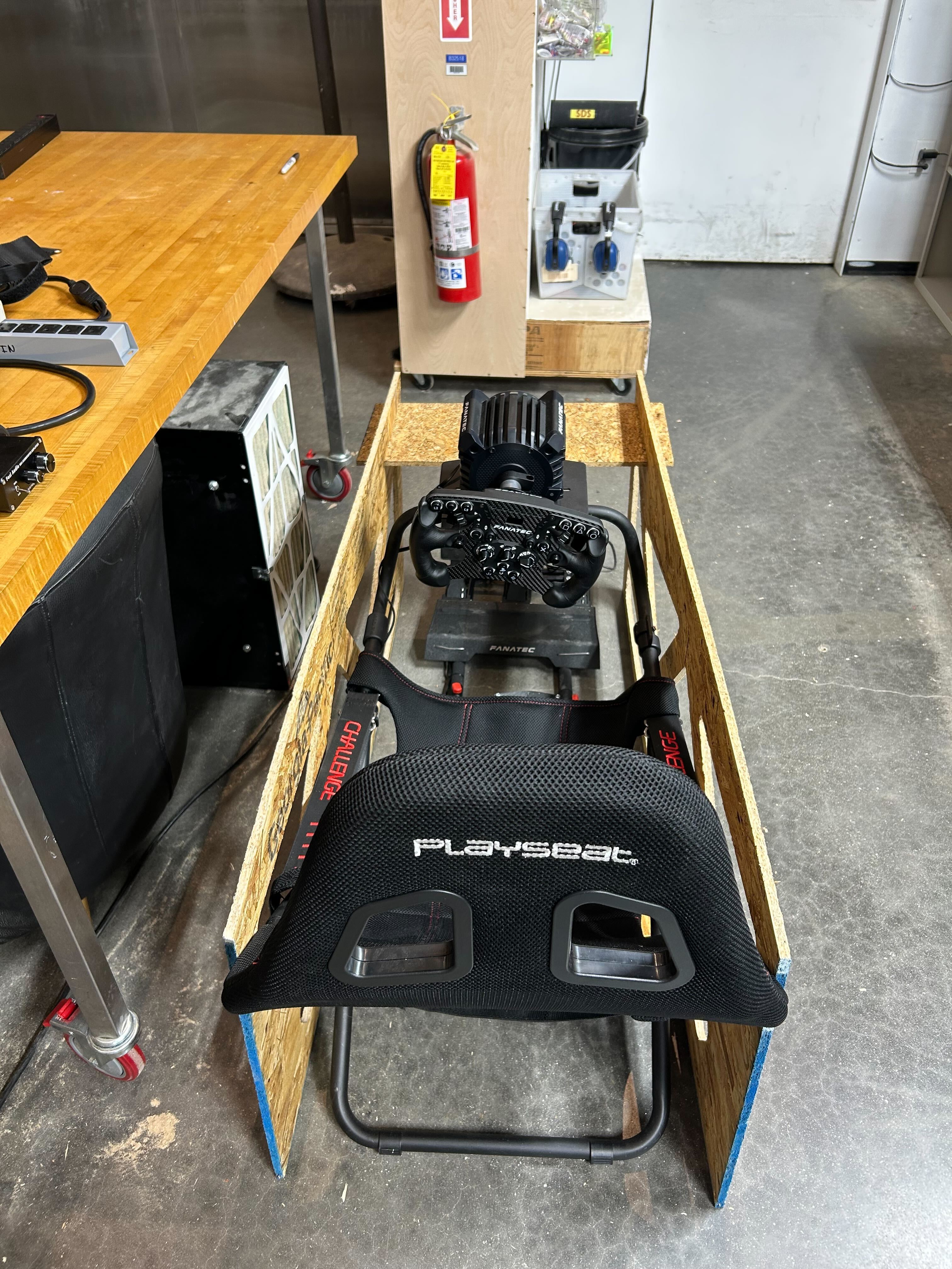
Back view of the completed racing sim side panel, displaying the machined details
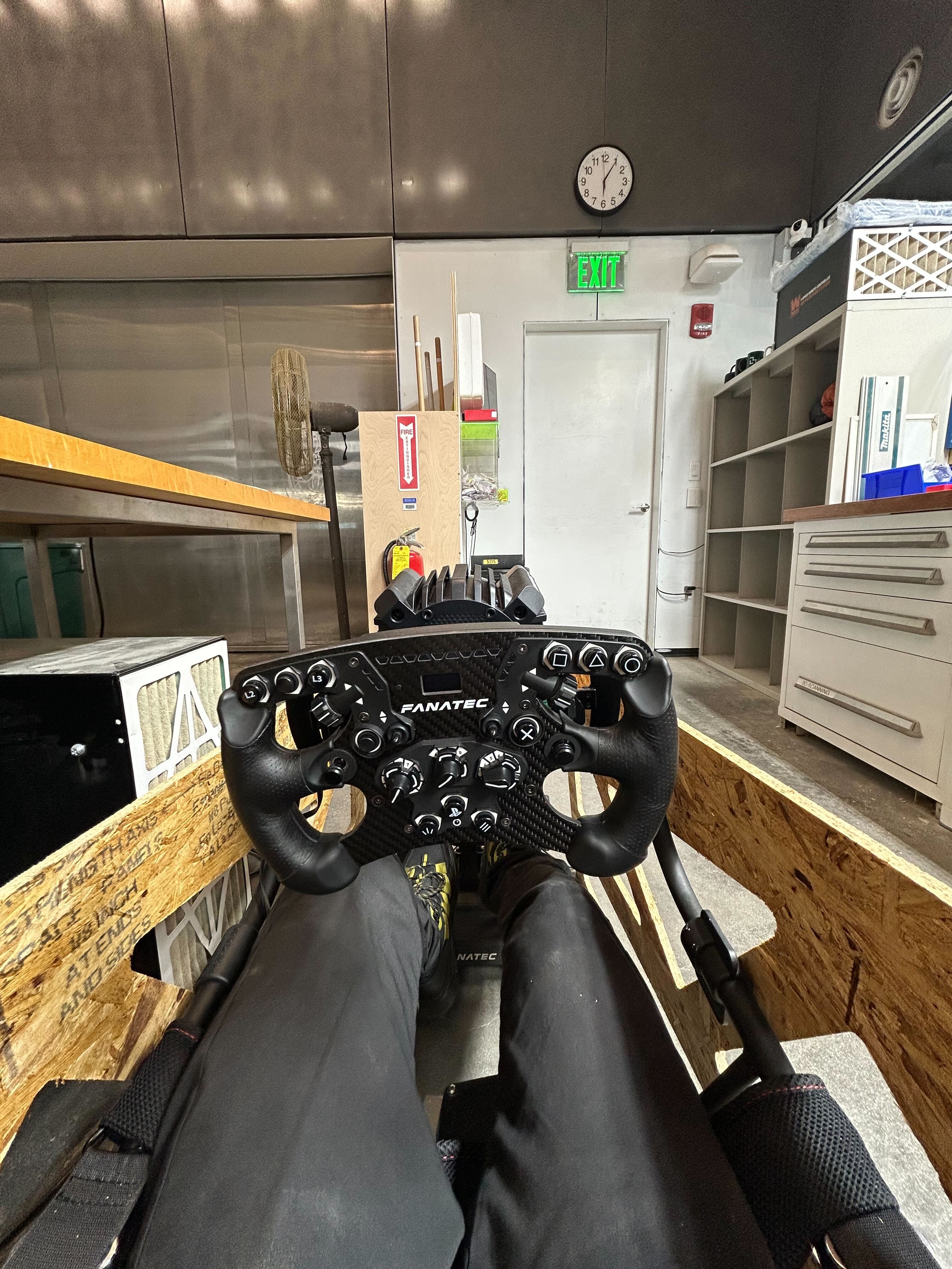
First-person perspective view of the completed racing sim side panel installed
Racing Sim Side Panel Project
Following the same computer-controlled machining procedure as the Buddha contour project, I also created a racing sim side panel. This project involved designing the panel profile, setting up the CAM operations in Fusion 360, and machining the panel using the quarter-inch end mill. The racing sim side panel required precise contour cutting to create the functional shape needed for the racing simulator setup. The machining process followed the same workflow - from CAD design through CAM setup to final CNC milling - demonstrating the versatility of computer-controlled machining for different applications.
Group Assignment: ShopBot Recitation
I attended the recitation with Dan where we learned about the basics of using the ShopBot. Due to time constraints, we didn't get to operate on the machines, but we went over the safety procedures thoroughly. The recitation covered important safety protocols, machine setup procedures, and the fundamental operations of the ShopBot CNC machine.
Challenges and Solutions
One of the main challenges I encountered was the complexity of the setup process and going through the Fusion software workflow. There are many steps involved in preparing a design for CNC machining, from importing sketches and setting up toolpaths to configuring CAM parameters and generating G-code. Each step requires careful attention to detail and understanding of the software interface.
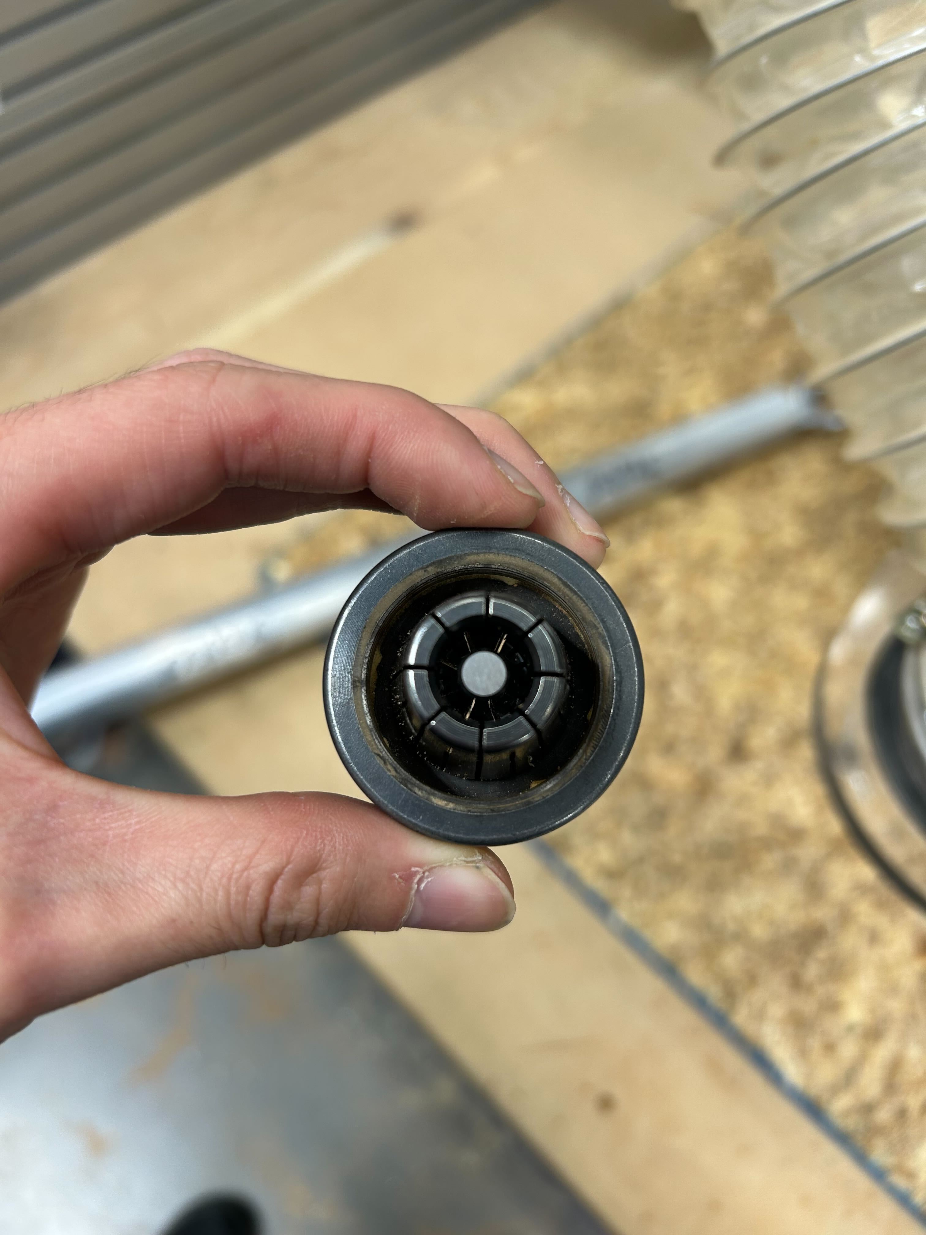
During my first attempt at machining, I made a critical mistake: I forgot to turn on the spindle before starting the operation. This resulted in breaking a quarter-inch end mill tool. The broken tool required replacement, and I had to learn how to troubleshoot and understand exactly how and why it broke. This experience taught me the importance of following a proper pre-machining checklist and verifying all machine parameters, especially the spindle status, before beginning any cutting operation.
During my first attempt at machining, I made a critical mistake: I forgot to turn on the spindle before starting the operation. This resulted in breaking a quarter-inch end mill tool. The broken tool required replacement, and I had to learn how to troubleshoot and understand exactly how and why it broke. This experience taught me the importance of following a proper pre-machining checklist and verifying all machine parameters, especially the spindle status, before beginning any cutting operation.
Reflection
This week's work demonstrated the powerful combination of photogrammetry, 3D processing, and CNC machining, as well as the versatility of computer-controlled machining for different applications. The Buddha contour project workflow from photogrammetry scan to final contour profile required careful attention to detail at each step - from cleaning up the scan in Maya to generating precise contours in the Fusion slicer program. The process of exporting DXF files and integrating them into Fusion 360 as sketches for CAM setup was particularly educational, showing how different software tools can work together in a digital fabrication workflow.
The Buddha contour project was especially interesting because it required translating a complex 3D form into a 2D cutting profile while preserving the essential characteristics of the original statue. The slicing process was crucial for maintaining the Buddha's recognizable features while creating a machinable contour. Running simulations in Fusion's CAM module helped verify that the toolpaths would produce the desired result before actual machining. However, the toolpath was too refined and the estimate time as over 10 hours, which was not feasible. So I decided to pivot into racing simulator.
The racing sim side panel project applied the same machining procedures to a different functional application, showing how the computer-controlled machining workflow can be adapted to various design needs. Both projects highlighted the importance of understanding the entire digital fabrication pipeline, from 3D scanning (for the Buddha) or CAD design (for the racing sim panel) through to CNC machining, and how each step affects the final outcome. The combination of artistic form (the Buddha statue) and functional design (the racing sim panel) with technical precision (CNC machining) created a unique intersection of creative expression, functional engineering, and modern digital fabrication techniques.
Attachments
Buddha Contour DXF File (.dxf)
3D Sliced Buddha Data (.step)
Fusion 360 CAM Project (.f3d)
Buddha Contour G-code (.nc)
3D Sliced Buddha Data (.step)
Fusion 360 CAM Project (.f3d)
Buddha Contour G-code (.nc)
Links