What an amazing ride this has been! Without a doubt, this is my favorite thing I've ever made for a class. I came into HTMAA wanting to sharpen my electronics skills. I certainly accomplished that goal and gained so much more along the way. I am so deeply grateful to the HTMAA staff and my fellow class mates!
Want to make your own OscilliSynth?? You can downlaod all of the relevant design and fabrication files here
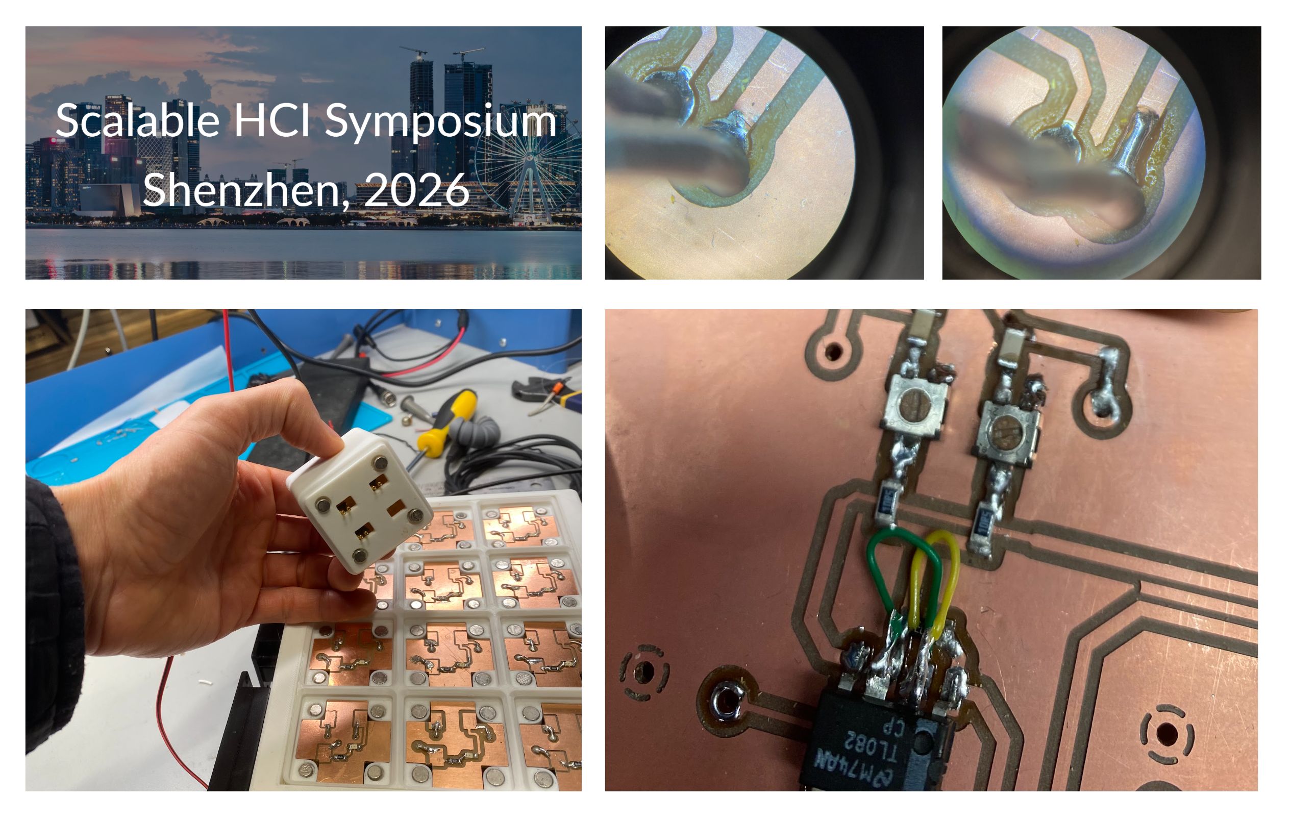
I'm very excited to share that I will be presenting the OscilliSynth at the Scalable HCI conference as part of the Research at Scale fellowship in Shenzhen. I imagine I'll get lots of good insights and feedback from that crowd of engineers and artists.
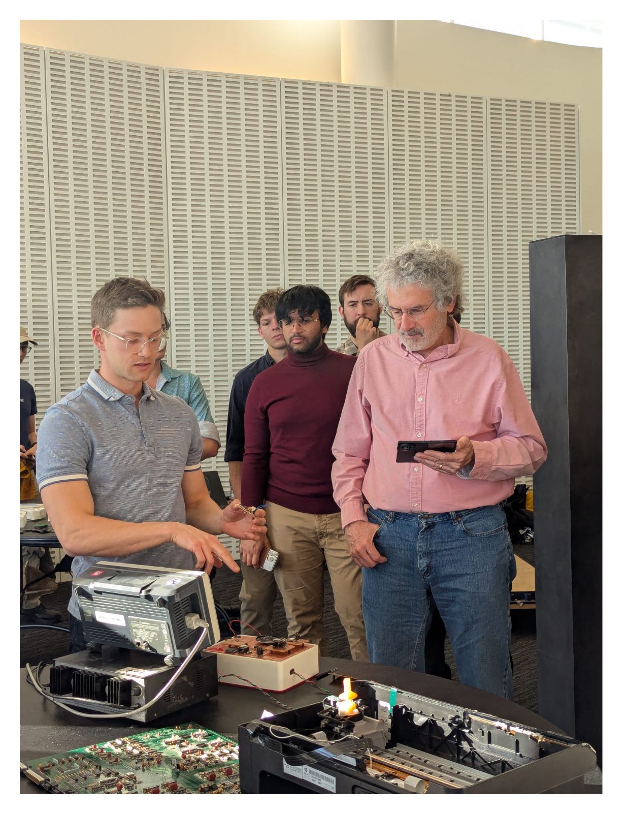
Speaking of excellent feedback: I demoed my project for Brian Mayton and Mark Feldmeier (fellow Responsive Environment folks) who are both extremely talented electrical engineers and they had tons of suggestions. For example, Mark spotted the issue with my mixer circuit immediatly, without looking at a schematic or the datasheet for the op amp...(aparently I had inverted my inputs! See below for the quick fix). I am eager to work with both of them to refine the design.
Furthermore, Claire Wang presented a really wonderful final project that had the kind of satisfying mangnetic snapping connectors that I would love to integrate into my project (see below). She was kind of enough to demo it for me the day after our final since I wasn't able to make it to her booth. Definetly check out her project page too!
TLDR: The OscilliSynth will live on!
Please read on to learn more about the process of making this project into a reality.
Process Pictures
Design
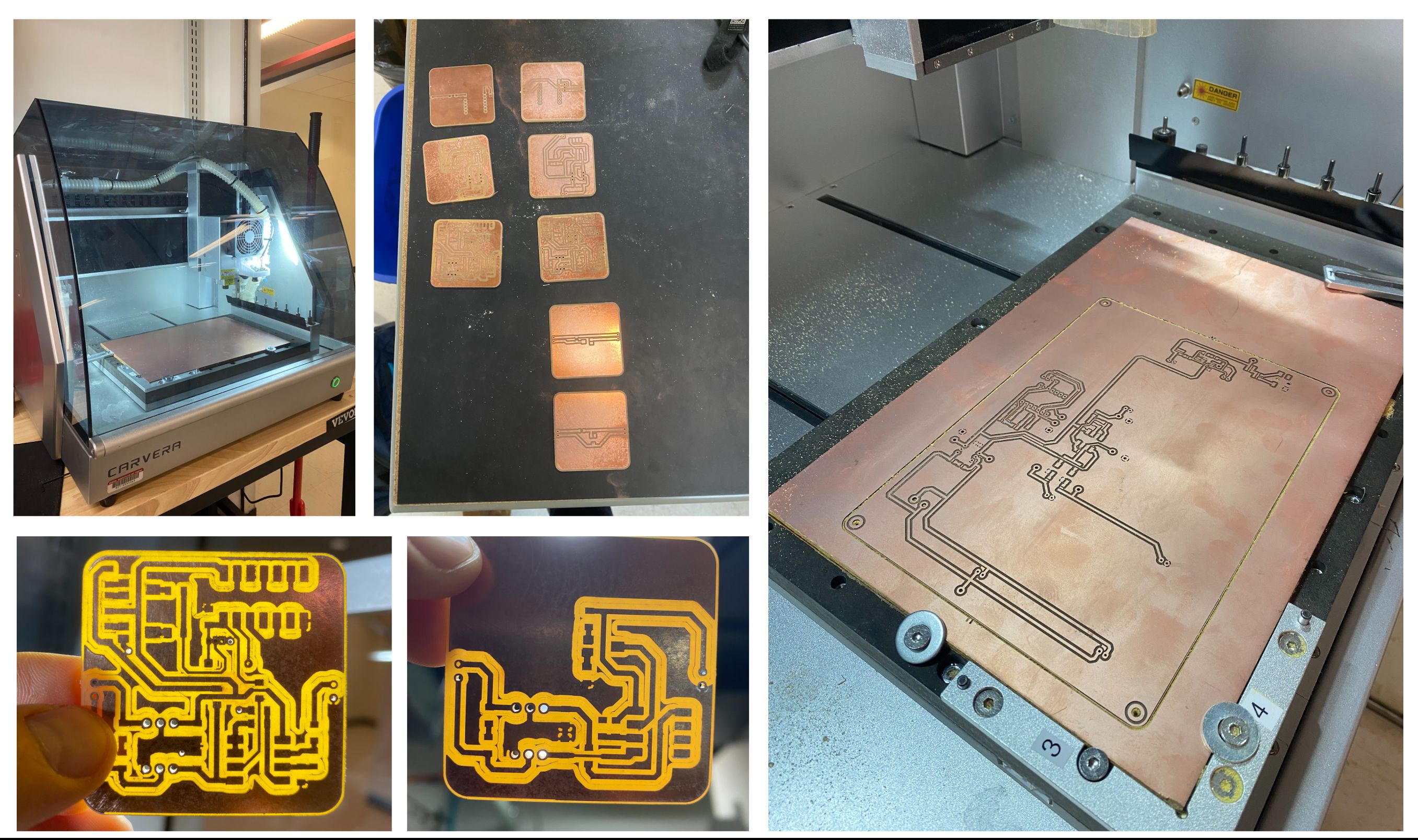
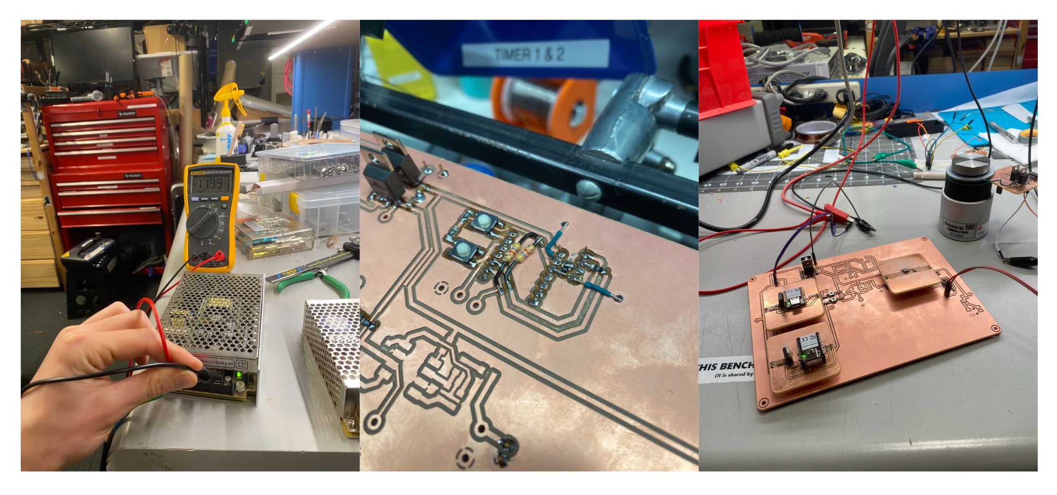
Mill
Build
Debug
Present!
Final Project Documentation Questions
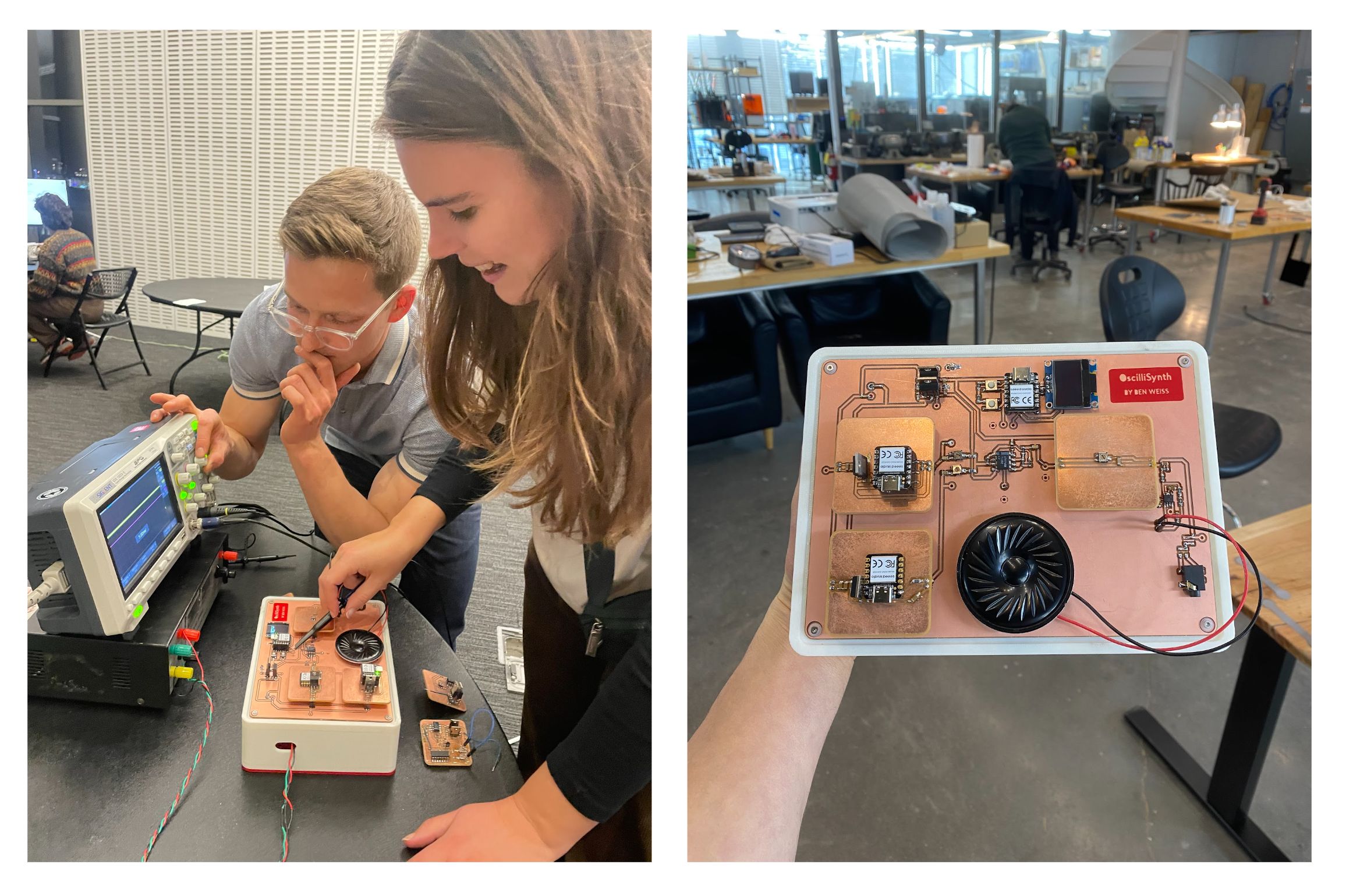
What does it do?
I designed a modular synthesizer which doubles as a teaching tool,
intended to help engineering students learn how to use an oscilloscope.
Who’s done what beforehand?
A very similar project exists by Erica Synths called the
EDU DIY Labor
.
Their system includes a built-in miniature oscilloscope, whereas my goal
was to train students on professional-grade oscilloscopes.
My system also emphasizes discrete waveform-generation modules rather
than embedding everything into one unit.
What sources did you use?
Practical Electronics for Inventors by Paul Scherz and Simon Monk
Additional sources are documented in the “Final Project Running Notes Doc”.
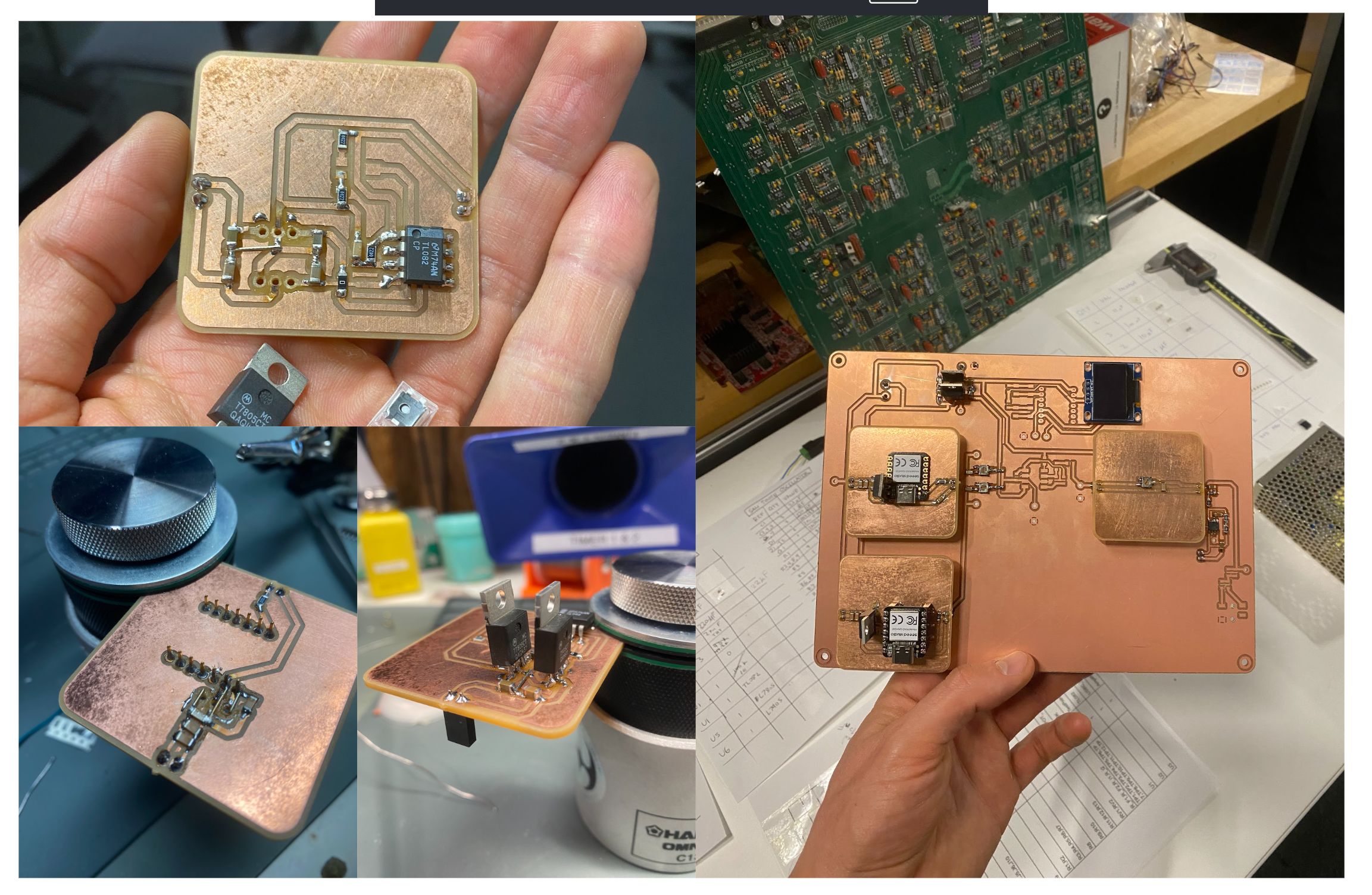
What did you design?
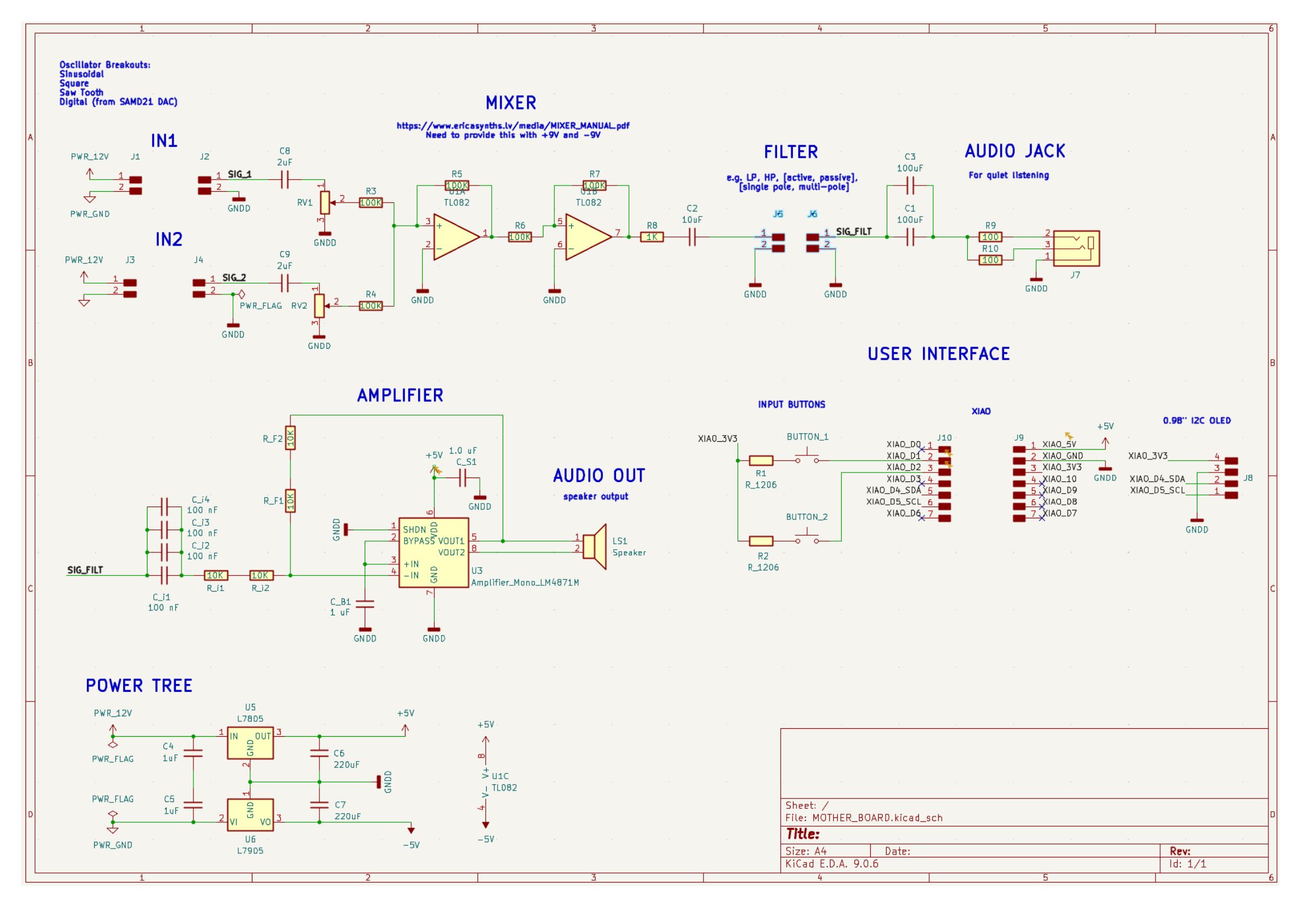
Electronics
Motherboard
User interface using a XIAO SAMD21, OLED screen, and two buttons
Input Oscillator Circuits
Analog square wave oscillator
Analog VCO (sawtooth oscillator)
XIAO SAMD21 oscillator board
SAMD21 (bare MCU) oscillator board
Filter Circuits
Variable passive low-pass filter
Variable passive high-pass filter
Software
Code for SAMD21 oscillator output
Code for the motherboard UI
Hardware
Enclosure using 3D printing and laser cutting
What materials and components were used?
Electronics
See BOMs below
Hardware
PETG for 3D prints
Acrylic for laser-cut base
Vinyl for logo cut on Cricut
Heat-set inserts and assorted fasteners
Where did they come from?
Electronics
Magnetic pogo pin connectors were special-ordered but not used
HTMAA Electronics Inventory
Responsive Environments component stash
Hardware
3D printing material from ResEnv
Acrylic stocked by Dan
Fasteners donated by Matti
How much did they cost?
Pogo pin connectors: ~$60
Estimated electronic components: ~$75
FR1 boards: ~$8
PETG: $5.36
Acrylic: $5
Total estimated cost: $133.36
What parts and systems were made?
Milled all PCBs on the Carvera
3D printed the case
Laser-cut the base plate
Only purchased electrical components and fasteners
What worked? What didn’t?
What worked
Digital oscillators (XIAO SAMD21)
User interface
Speaker
Modular design
Integration and packaging
What didn’t
Mixer circuit
Headphone jack
Analog oscillators
What are the implications?
The project shows strong promise as an educational tool and motivates
continued development, including improved usability and additional
oscillator and filter modules.
Final Project Running Notes Doc
When the debugging gets tough, I turn to google doc to take my notes. This makes it really easy for me to add hyperlinks and images. If you would like to see my log of work in the couple weeks leading up to the final, you can find that here, for as long as that google link holds up. I am pasting the text (no images) below for posterity. I used a similiar document to track the more visual aspects of my debugging and fabrication process here.
12/15/2025
[done] Make a high pass filter
[done] Tidy wiring
[done] Solder on a test point at output
[done] Vinyl cut logo
Software
Change instructions to start with oscillators off the board
Have both do frequency sweeps, two solid tones, and then maybe a scale
Laser cut top panel
12/14/2025
Update as of 2:30pm
Have two versions of an enclosure printing (one simpler and one more complex, enclosing the power supply)
Matti helped fix my GitHub issue; can now update website
Ready to dive back into electronics
Plan for today
[done] Install UI XIAO, screen, and buttons
Priorities
Get demo working with melody on one XIAO and high frequency on the other
Use low pass filter to remove additive noise
Make basic UI on XIAO
Finish installing motherboard into 3D printed housing
Connect to transformer
Install headphone jack
Try SAW/SQUARE oscillators on breadboard
Test and install mixer circuit
Execution notes
Installed UI XIAO, screen, and buttons
Screen required pull-up resistors and better connector seating
Buttons verified using Arduino example
Sawtooth oscillator debugging with Anthony
Resolved transistor biasing and pot wiring issues
Mixer and headphone jack initially unreliable
System functional at 3AM
Other notes
Transformer cannot provide sufficient current on negative rail
High pass filter planned for tomorrow
Reducing R3/R4 increased loudness but introduced coupling issues
12/13/2025
Populating square tooth board
Capacitor package mismatch discovered
Datasheet review for regulators and bypass caps
Dual power supply debugging
[done] Get motherboard working with single SAMD21 oscillator
[done] Get motherboard working with two XIAO oscillators
Execution notes on amplifier testing and SAMD21 board population
Resolved GNDD / DC blocking capacitor issue
Successfully mixed two XIAO oscillator outputs
12/12/2025
Spent all day milling boards
12/11/2025
Revisiting XIAO oscillator breakout circuit
Decision to remove buffer amplifier
Switching power input to USB-C module
Machining SAMD21_XIAO_BREAKOUT
12/10/2025
SAMD21 XIAO breakout
Adding variable op-amp amplifier
12/9/2025
Exploring dual rail power solutions
Decision to use 7905/7805 regulators
VCO voltage considerations
Motherboard DC blocking capacitors
OLED screen testing
12/7/2025
Design review and footprint correction
Laser engraving workflow and settings
12/6/2025
Completed oscillator and filter schematics
Open questions on power splitting
Replication of SEEED SAMD21 schematic
Encouragement from Feng Zheng
12/5/2025
Component selection and substitutions
Decision to use 5V / -5V system
Designing oscillator and filter circuits
12/4/2025
Design review feedback from Dimitar
Mixer topology decisions
Single vs dual rail clarification
12/1/2025
Multi-board KiCad system planning
Connector definitions and MVP scope
11/30/2025
Erica Synth manuals
UX narrative walkthrough
Essential features and nice-to-haves
Historical references
Midterm Review
The slides for my midterm review can be downloaded here.
Week 9 Update
My latest idea: I'd like to create a modular synthesizer which functions as a training tool for oscilloscopes. O-scopes are extremely useful, but learning how to use them is challenging.
I'm imaging a system with the following main components
Microcontroller based signal generator
Modular synthesizer circuits that can be swapped in and out
Speaker
[Stretch goal] User interface with screen and buttons
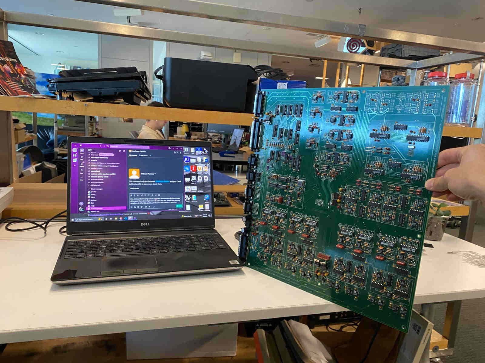
[Stretch goal] Minimize the number of components purchased new by using "found" components around the lab and harvested from old PCBs and other electronics waste streams
Concept of Operation
After placing a particular module into the system, the user will be prompted to probe a variety of test points along the signal path with their o-scope. In this way, they will begin to build intuition for how signals are processed by PCB circuits and viewed on oscilloscopes.
Week 5 Update
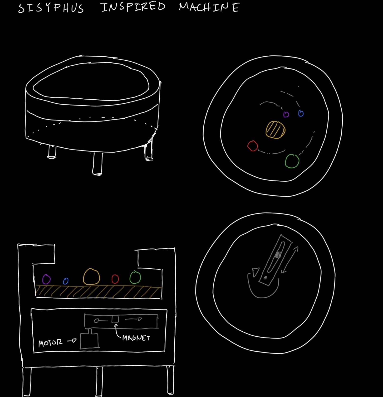
Okay…possibly doing a 180. Now considering what does it mean to compost electronics? How might I reuse electronics waste around MIT to make a...FRANKENSYNTH?!?
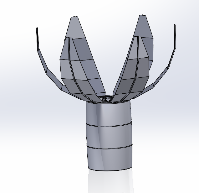
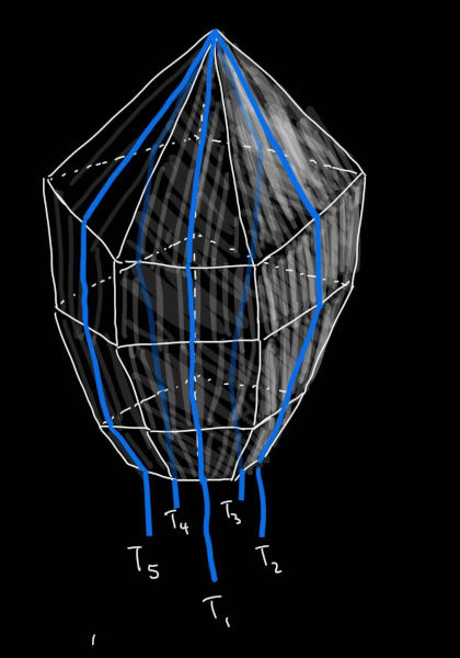
Initially, I envisioned having the structure of the form be some kind of faceted, irregular polyhedra, where each column of panels pulled away from the center, kind of like segments of an orange.
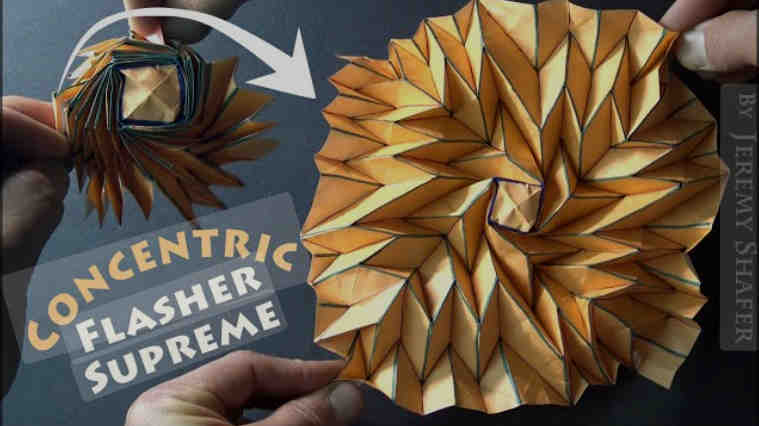
This week, I spoke with Alfonso (one of the TA's) who specializes in origami structures. I showed him a piece of installation art, which inspired my interest in using origami for this project (see here). Noting that the form of folding in that project is rather inefficient, he encouraged me to look up origami flashers
I am really excited to delve into this area of research. I think that it could be the key to making my final project work!
Brainstorm
Much of my time working on the first assignment was spent doing sketches, trying to come up with a worthy idea. I sketched up a few things before settling on a winner.
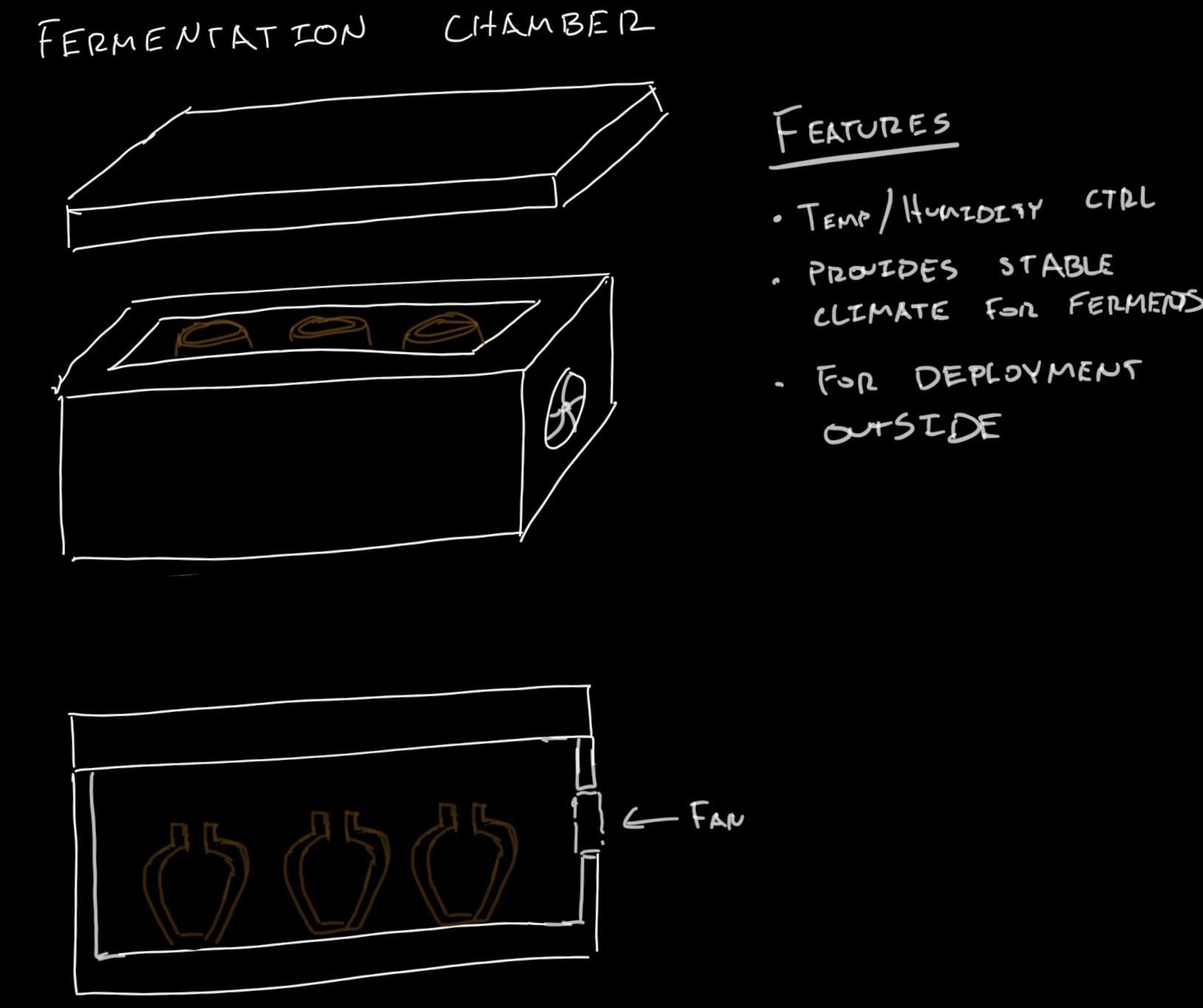
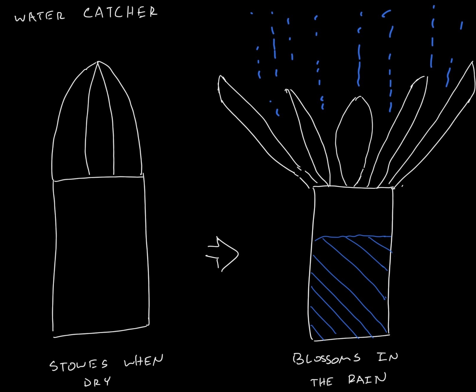
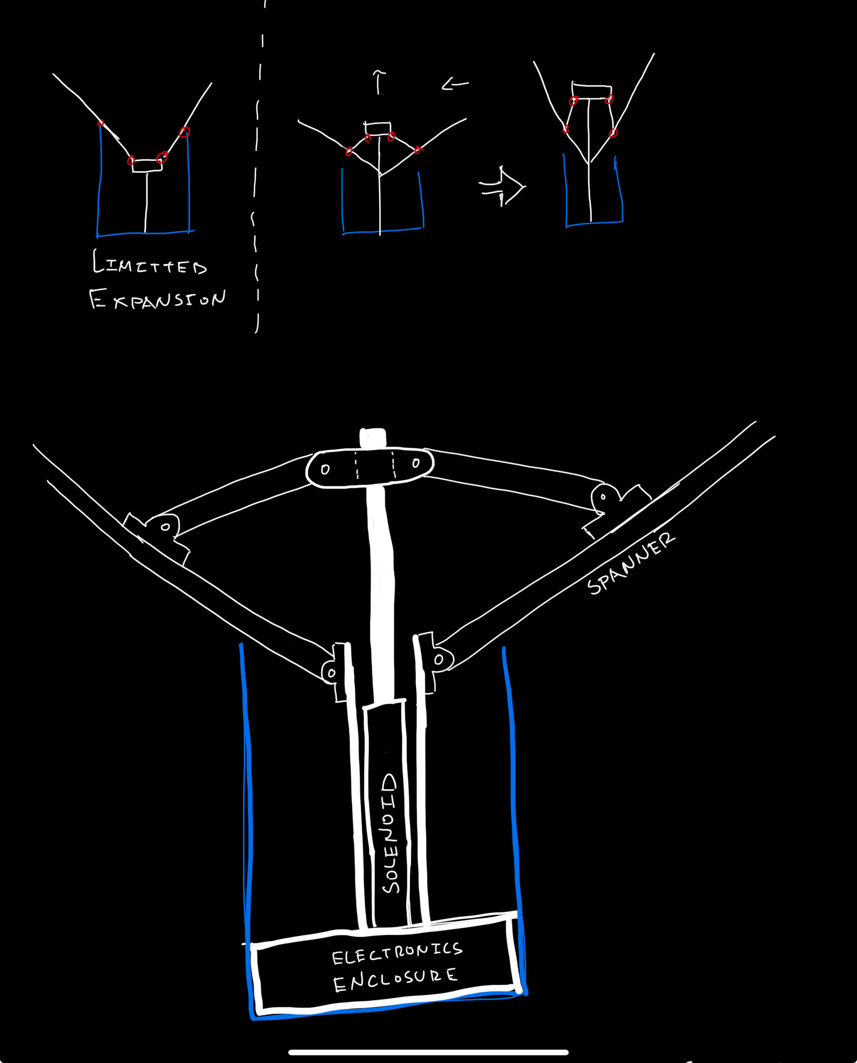
My final project proposal is inspired by my time spent working in community gardens. As summers grew hotter and rain storms became more infrequent, I dreamed of implementing some sort of rain water catchment system. The issue is that any large rain catchment system would block sunlight from reaching the plants below.
I propose to make a deployable rain catchment system called the Water Lily (working title). When it rains, the system will blossom, maximizing surface area. When it is no longer raining, the system will stow itself so as not to block sunlight. The details certainly need to be fleshed out, but there’s the idea!