In the hopes of making one of the input boards for my final project, I decided to participate in the laser PCB wildcard session. Going through the process of designing my first breakout board for a bare microcontroller chip was really instructive!
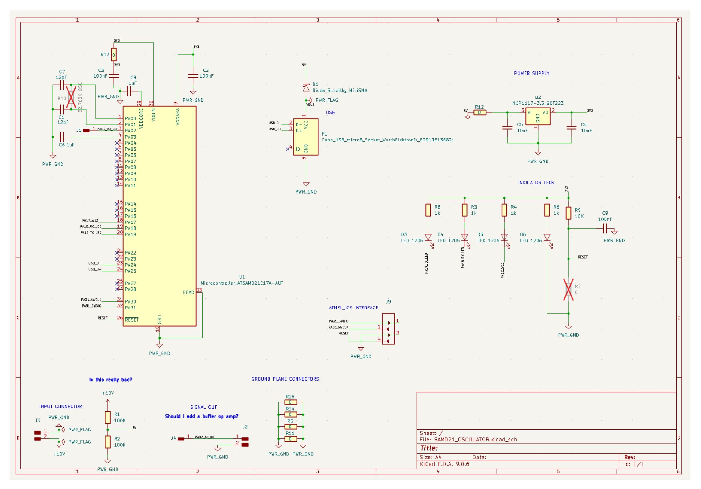
I used the XIAO SAMD21 Schematic as a reference. I couldn't simply copy and paste what they had because their design uses the QFN48 package, whereas we had access to the QFN32 package.

In order to map the components from their schematic to this slightly differnt package, I used the SAMD21 datasheet (Chapter 7: I/O Multiplexing and Considerations).

Next, I laid out the PCB design (which was perhaps my most complicated layout process yet)!

And finally, Quentin whizzed me through the process of laser engraving it on the xTool F2 Ultra.

Sadly, after collecting all the components I would need to populate the baord, I hit a critical road block upon soldering the SAMD21 to the board. While I was trying to clean up the solder bridges between some of the legs, I accidentally ripped off the trace leading to 3v3 in, rendering the baord pretty much unusuable (see below). Alas, I still found this to be a really instructive experience! Looking back at my layout, I realzied that I should have made the traces thicker as soon as I was far enough away from the chip to do so. Next time, I will also route the 3v3 line differently in the future, avoiding sharp angles so close to other traces.

All KiCAD Design files required to reproduce this board can be downloaded here SAMD21_XIAO_OSCILLATOR.zip.
Return to Home Page