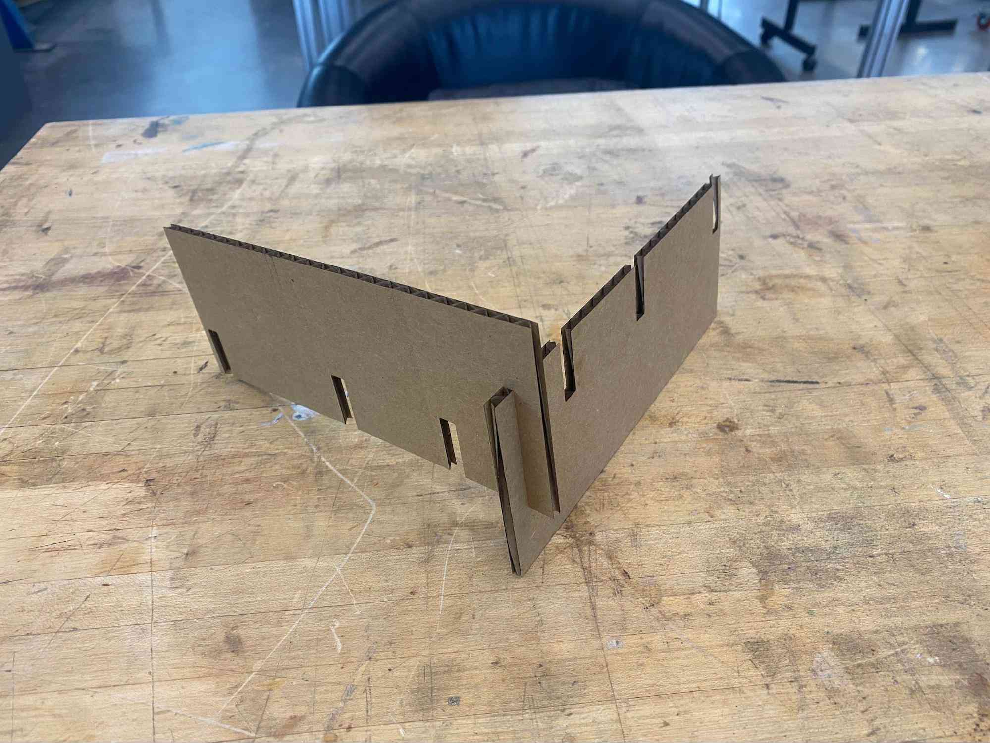
The first part of this week’s assignment was to work in a group to determine appropriate settings for the laser cutter (focus, power, speed, kerf). I collaborated with Matti Gruener and Jacqueline Orr on this. Jacqueline used Fusion to model a “comb” for us to use in our testing. We were working with the xtools laser cutter. Through this process we found the following to be effective settings for working with cardboard sheets (~0.15” thick):
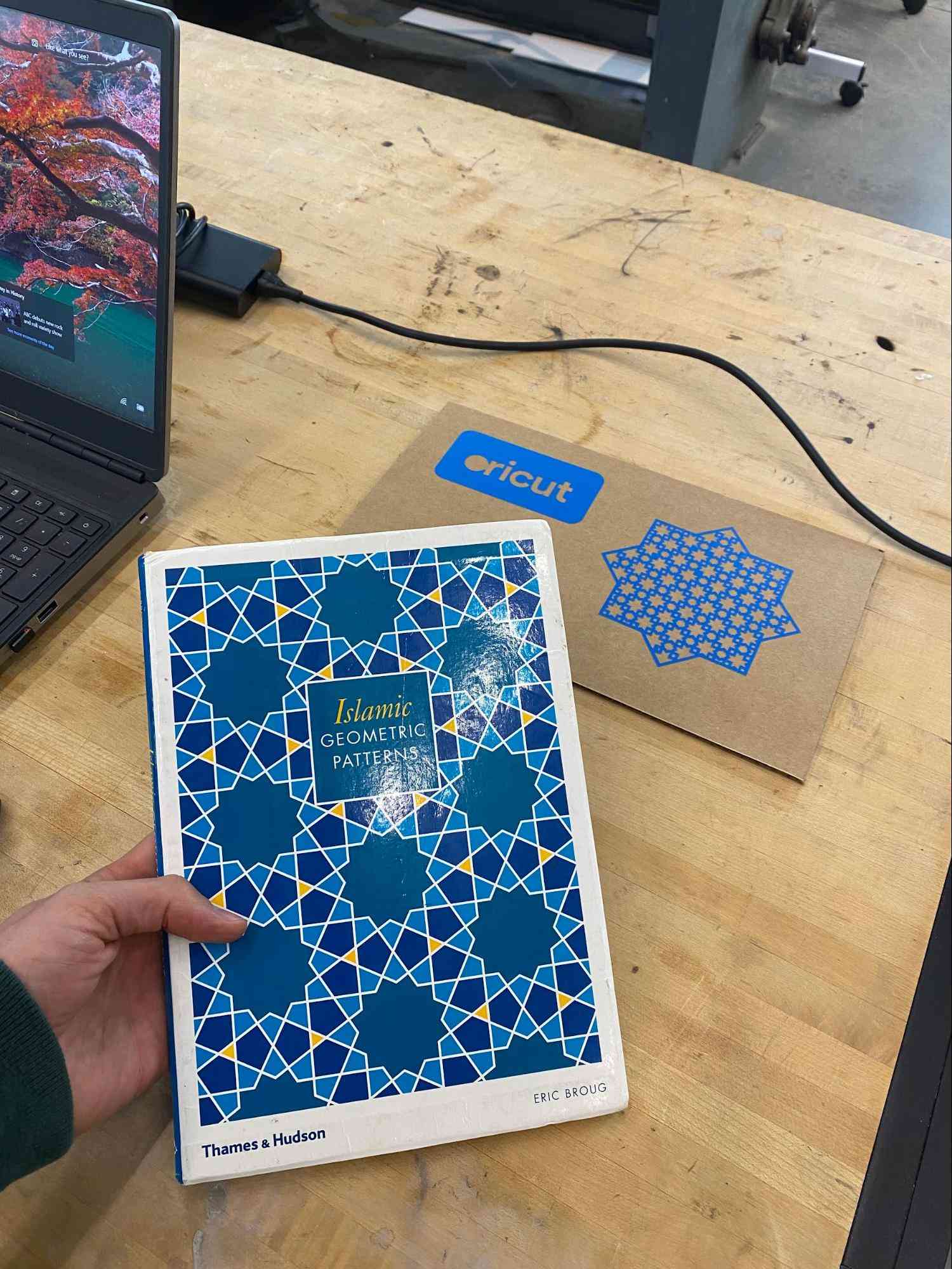
I’ve long been interested in Islamic geometric designs and patterns. This project seemed like the perfect opportunity to apply this interest to a fabricated object. My intent was to model a pattern in SolidWorks based on the work of Eric Broug, but alas, I ran out of time. I was still able to put together a cool drawing, but didn’t get to fabricate it. Instead, I followed the very helpful instructions embedded in the Cricut’s software and chose a template to cut out.
For this part of the project, I was inspired by the work of Magnus Wenninger, one of my other favorite geometers.
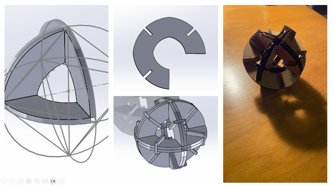
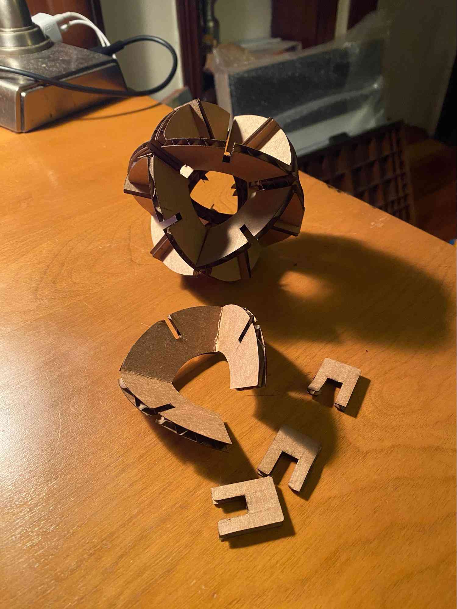
In order to make this model, I followed the steps outlined in his book to derive the spherical triangles for his octahedral models. I had to adjust his approach slightly given that all of his models are made out of paper of negligible thickness. Overall, I am happy with the way it came out, but I certainly have some ideas for improvements! What’s cool about the process I developed is that it is totally generalizable to any spherical polyhedra composed of triangles.
This particular model is composed of 8 identical spherical triangles, each of which is cut out as a continuous strip of cardboard with 2 scored lines. The 8 pieces are then joined together with the separate connectors. One thing I didn’t see coming is how much effort it took to figure out how to get the xTool machine to recognize scoring vs cutting lines. Ultimately, I had to export my flattened part to a drawing file, and then draw a sketch on top of the part. I could then export the sketch lines (scoring) and the outline of the part (cutting) as separate layers in the dxf file. Each of the spherical triangles is both curved and bent. Furthermore, this sphere can be assembled in 3^8 ways since each of the triangles can be inserted in 3 distinct rotations.
Solidworks part and dxf's can be downloaded here HW2_MODEL_FILES.zip.
Return to Home Page