Please see this link for my group's assignment (group #2).
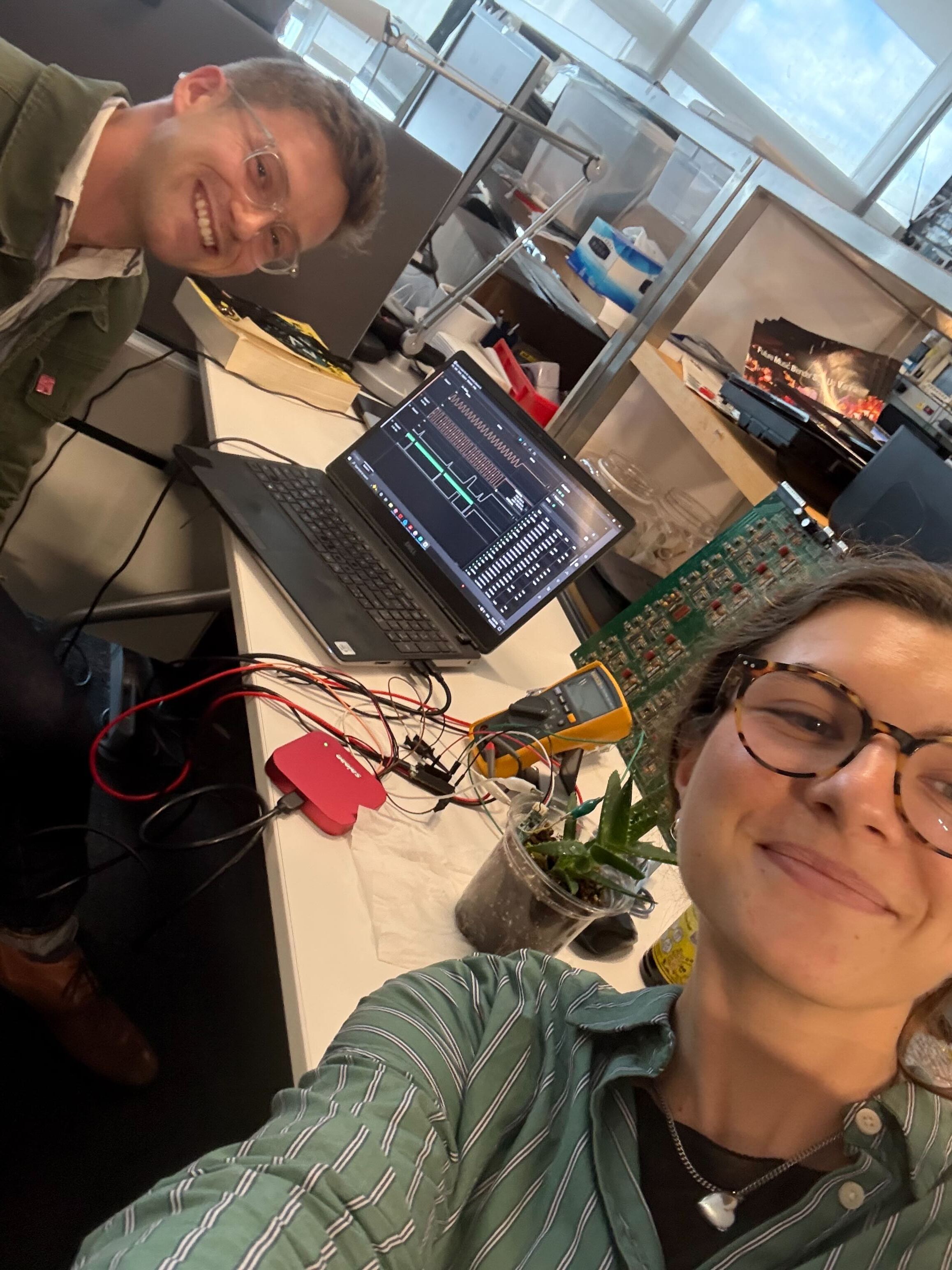
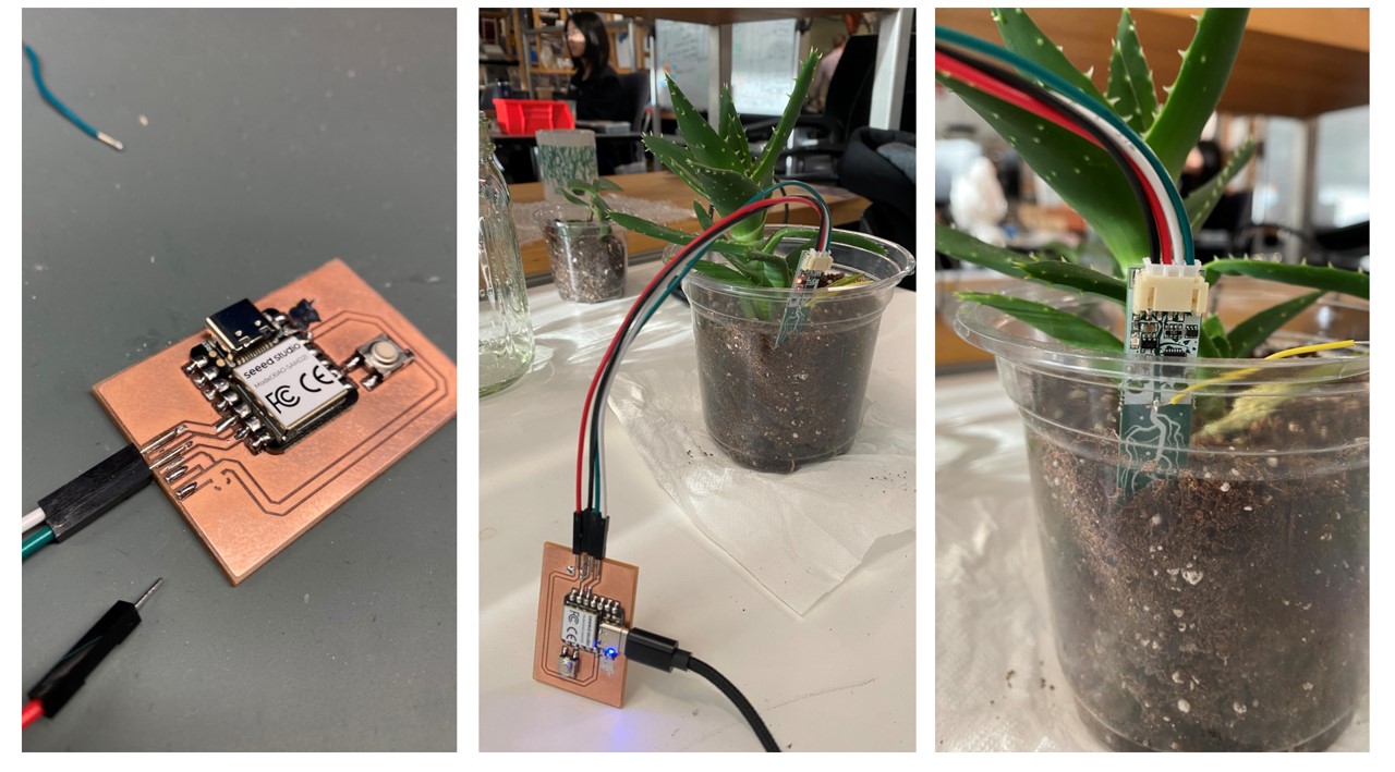
This week, I finally got to use a sensor I’ve had kicking around my electronics box for sometime now: Adafruit’s capacitative soil moisture probe (link).
I decided to fabricate a new, simple PCB for this in order to review the KiCAD workflow and given that my old board didn’t have a convenient way for me to integrate this new sensor. In order to connect this sensor with a new MC, I needed to make a PCB with just four connections: power, ground, SDA and SCL. Additionally, I decided to add a button to the board in order to act as a "take measurement" trigger. I didn't end up using it, but it's nice to have for future work.
The first step was to sketch this out in a KiCAD schematic. At first, I tried to just draw the attachment points for my sensor as wires in the schematic, but I got the following error.
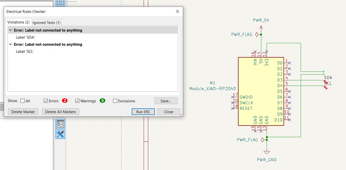
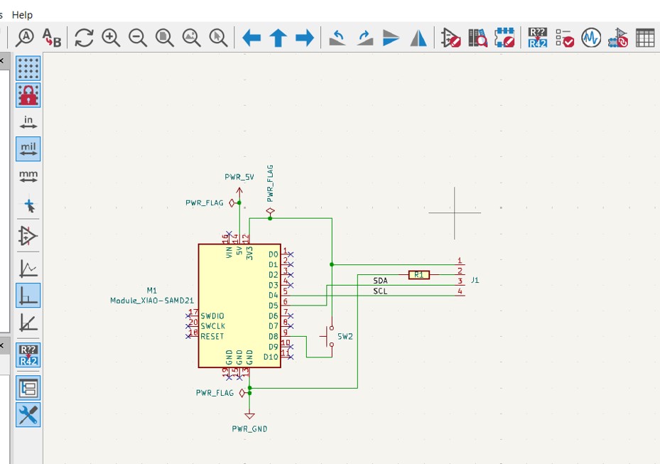
Turns out, KiCAD doesn't like wires that don't connect to anything. So, I dropped in a component and made the connections. Magically, the errors in my rule checker disappeared!
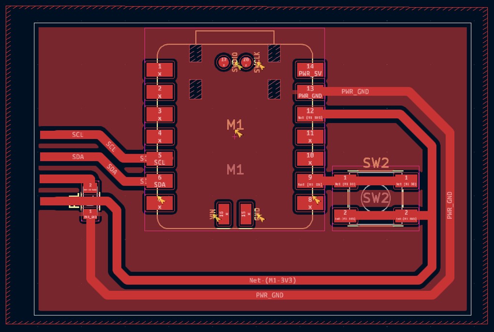
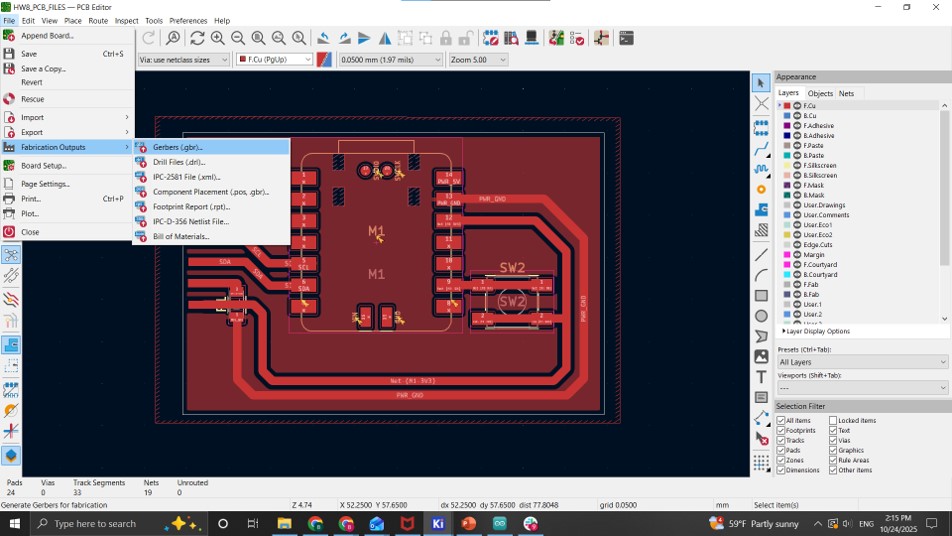
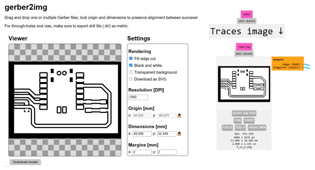
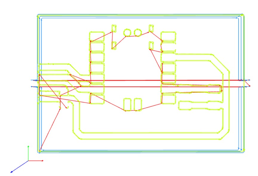
Next, I laid out the PCB in the PCB editor, being sure to make my tracks sufficiently wide (40 mil in this case).
Once my PCB passed the DRC, I was ready to export the gerber files, convert to PNGs, and generate a tool path using the mods tool. Please reference the Carvera PCB tutorial for step by step guidance on this process.
The board came out quite nicely on the Carvera. After milling, I gently sanded the surface to remove burs and then soldered the leads of the sensor directly to the traces. It would have been more elegant to use a connector here, but I wanted to keep things very simple.
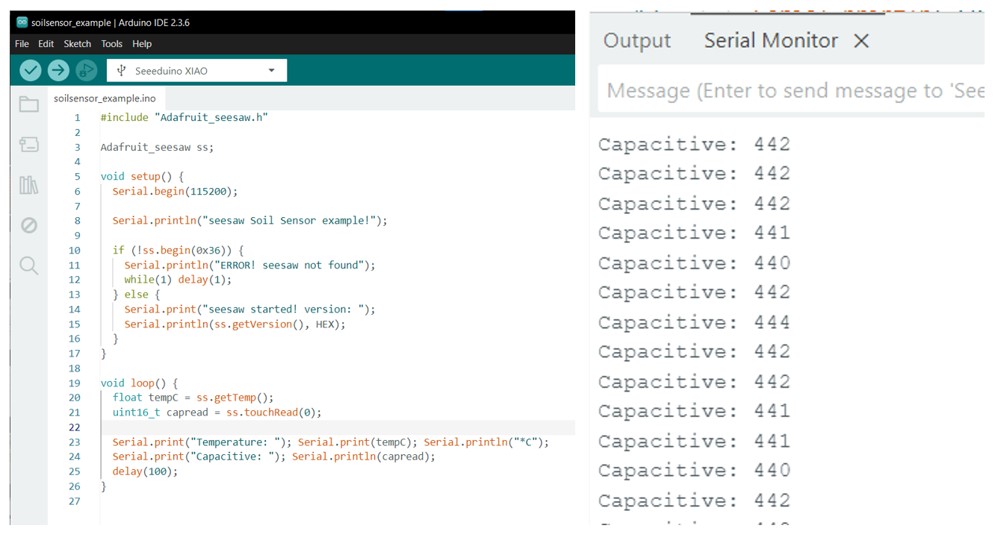
In order to get readings from the board, I ran the test code from the Adafruit Seesaw Library. See the adafruit tutorial for a step-by-step guide through this process. The following image shows the sample code along with the output I saw in my serial terminal.
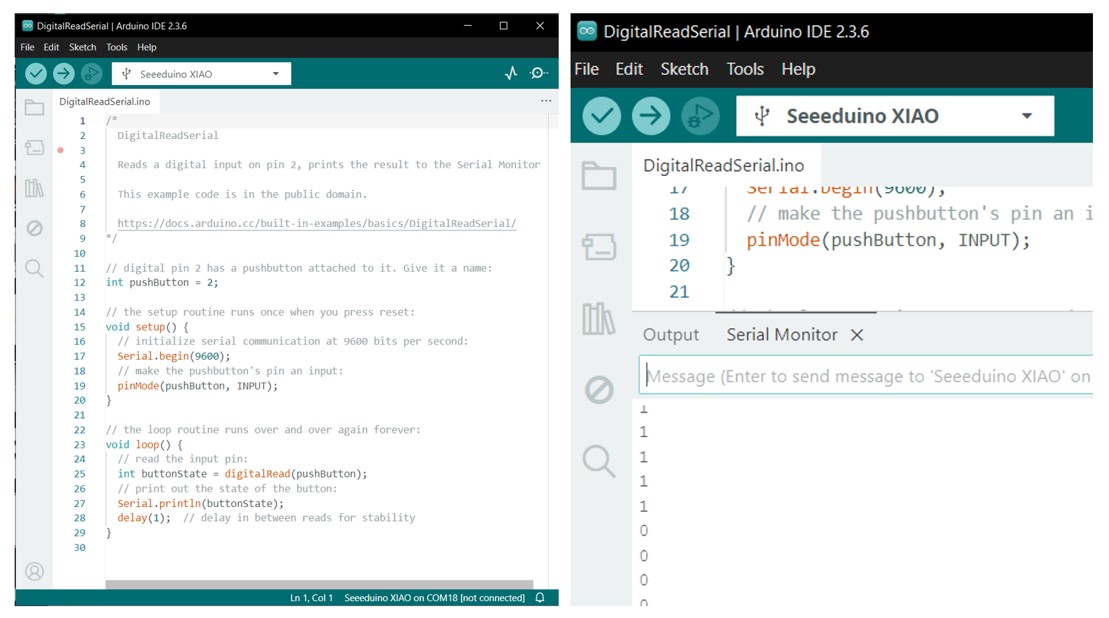
I also used the arduino example code DigitalReadSerial (which can be found under file > Examples > 01.Basics > DigitalReadSerial) to see the state of my button. At a later point in time, I may use this button to trigger a "get soil moisture" event.
My KiCad files for his week can be downloaded here.
Return to Home Page