Welcome Computer-Controlled Cutting or the C-suite of HTMAA
Construction kit brief
This week we learned the laser cutter and vinyl cutter. The assignment: design a construction kit that can be assembled in multiple ways, prepare files for cutting, and document the process.
Picking a direction: a buildable sundial
Building on Week 1’s parametric adventures, I explored a sundial as a construction kit. I find sundials a beautiful example of simple geometry revealing something as complex as the passage of time—and a good way to learn the laser cutter.
What is a sundial?
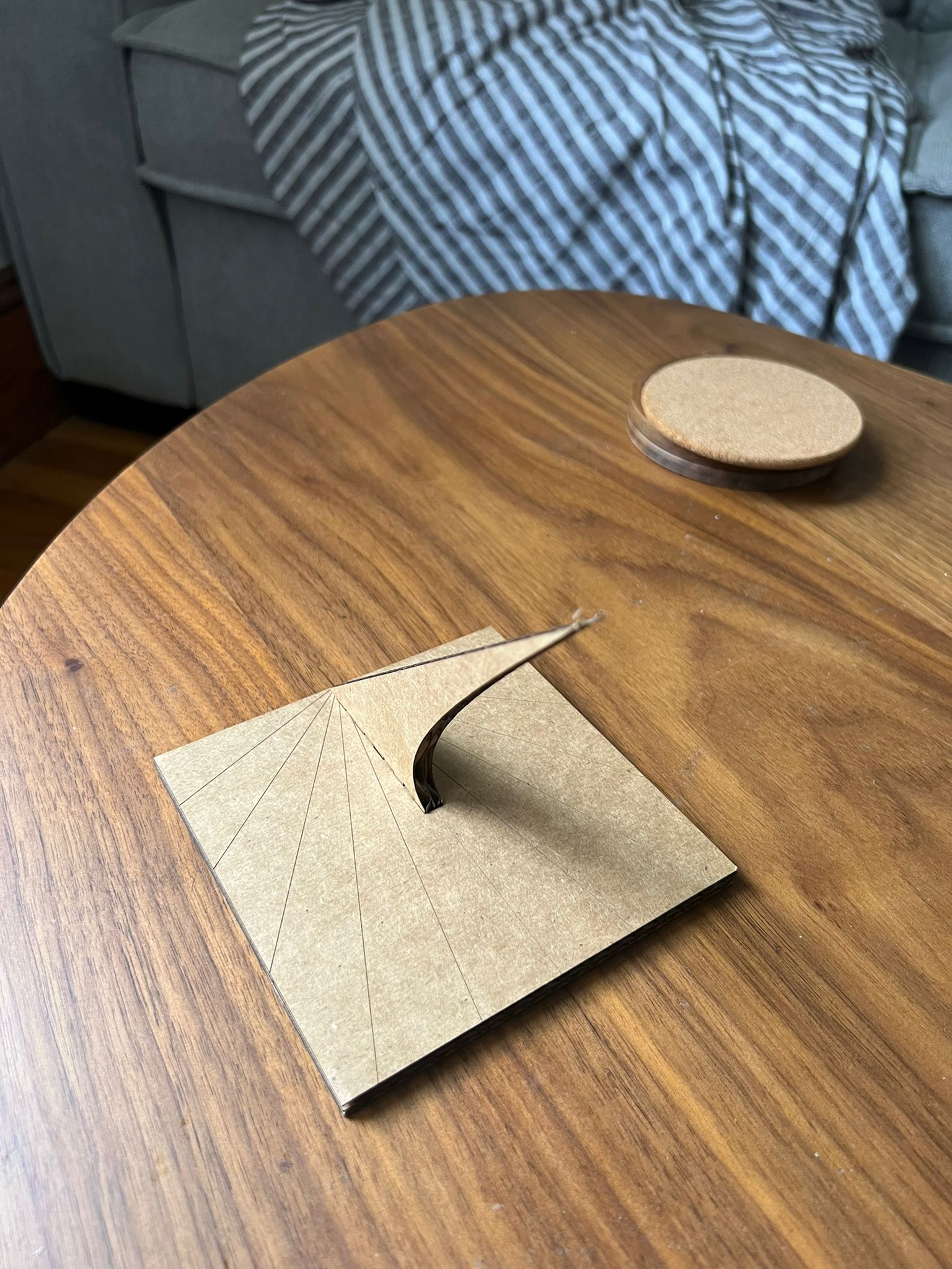
A sundial tells time using the Sun’s apparent motion. In its simplest form it has a flat plate (the dial) and a gnomon that casts a shadow. As the Sun moves, the shadow aligns with engraved hour lines. There are many types; see sundials.info/types. I’m aiming for an adaptable kit that can be assembled either horizontally or vertically by flipping/rotating parts and swapping gnomon slots.
“As is the case with other Sundials, the Gnomon remains pointing North and at an angle equal to the Latitude of where the Sundial is to be positioned…” — DT Online: Exploring Sundials
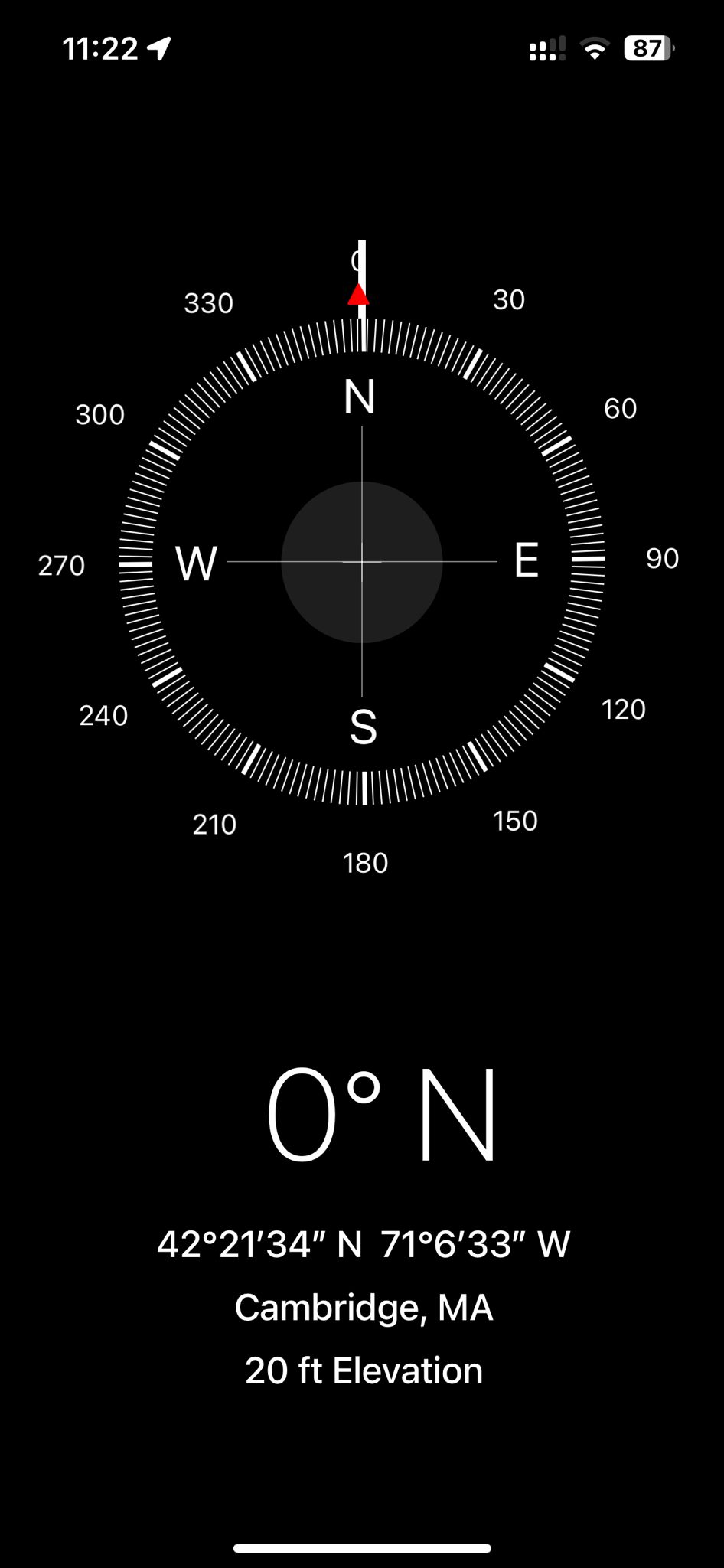
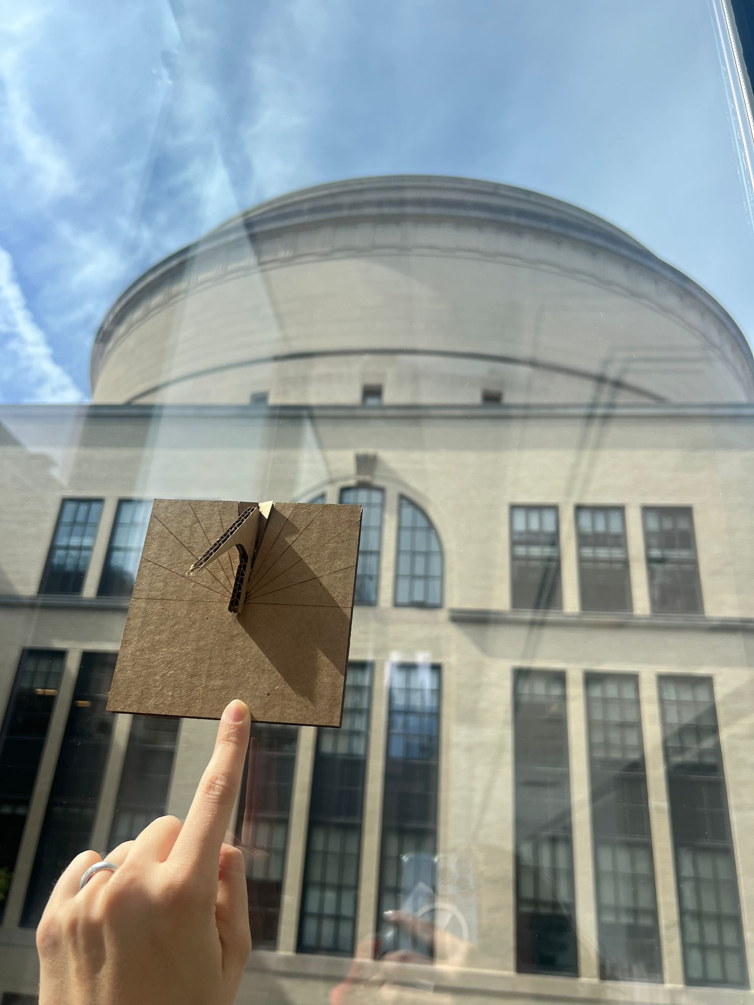
Site & latitude (Media Lab, MIT)
Let's say we want to build the sundial for the MIT Media Lab, where HTMAA is based. Then we need to use the latitude: L = 42.3604°. The gnomon must point North and be set at an angle equal to latitude relative to the dial plane (for a horizontal dial), which is perfect for parametric constraints.
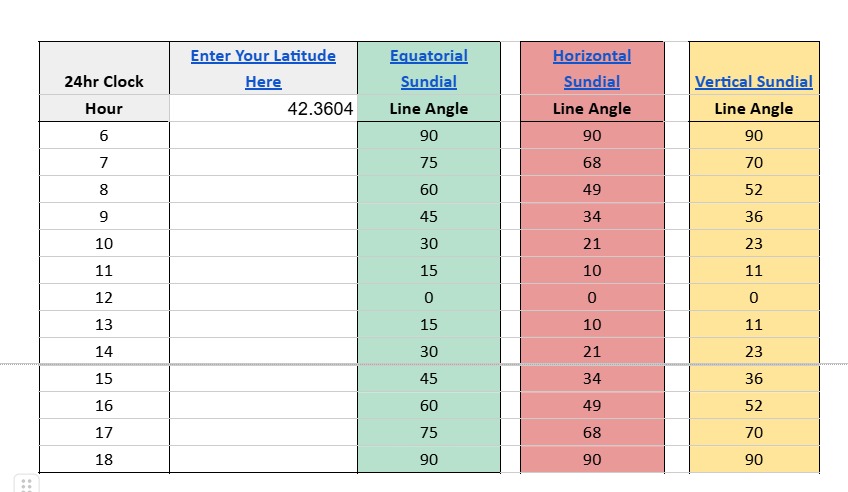
Hour-line angles
Using a standard calculator/designer (see Horizontal Sundial Designer), I collected typical hour-line angles (degrees from the noon line). Values are symmetric around noon:
| Hour | Equatorial Line Angle (°) |
Horizontal Line Angle (°) |
Vertical Line Angle (°) |
|---|---|---|---|
| 6 | 90 | 90 | 90 |
| 7 | 75 | 68 | 70 |
| 8 | 60 | 49 | 52 |
| 9 | 45 | 34 | 36 |
| 10 | 30 | 21 | 23 |
| 11 | 15 | 10 | 11 |
| 12 | 0 | 0 | 0 |
| 13 | 15 | 10 | 11 |
| 14 | 30 | 21 | 23 |
| 15 | 45 | 34 | 36 |
| 16 | 60 | 49 | 52 |
| 17 | 75 | 68 | 70 |
| 18 | 90 | 90 | 90 |
Parametric setup (Fusion 360)
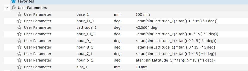
I set the design up so that only two user parameters need to change for a new build:
- latitude_deg — controls the gnomon angle relative to the base.
- slot_thickness — equals measured material thickness + kerf allowance for a snug fit.
All sketches (hour-line construction, gnomon triangle, tab/slot, and alternate vertical/horizontal placements) reference these parameters. Changing latitude or stock thickness automatically regenerates the geometry, which makes the kit portable to any location and material.
Design steps — lab notebook
-
Sketch base + noon line.
Create the base circle/plate; add a construction line for the noon line.
Use constrained angles for hour lines referenced to
latitude_deg. - Project hour lines. For the horizontal plate, project angles from the noon line using the angle table above. (Same file includes a vertical-plate sketch on its own plane.)
-
Gnomon triangle.
Constrain the gnomon’s hypotenuse so that its angle to the base equals
latitude_deg. Add tabs referenced toslot_thickness. -
Parametric slots.
Slot width =
slot_thickness; slot depth scales with plate thickness. Create mirrored slots for vertical/horizontal assemblies. - Engrave vs cut layers. Separate construction/engraving (hour lines, numerals) from cut geometry (outer profile, slots).
- DXF export. Export each profile (base, gnomon) as DXF for the laser pipeline.
Takeaways: separating parameters early saved a lot of time; engraving layers needed their own export to keep the cut file clean.
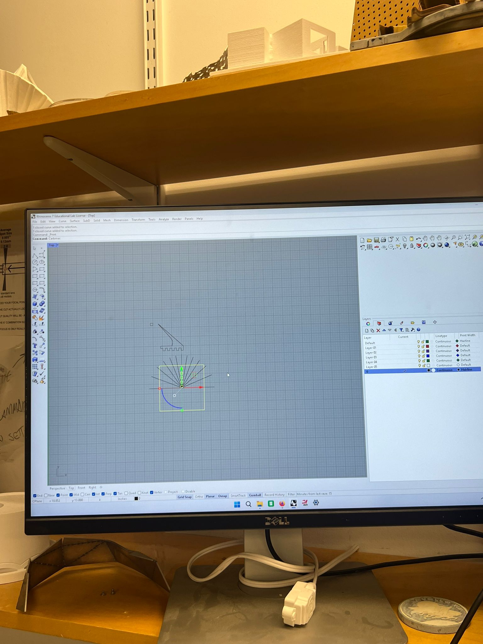
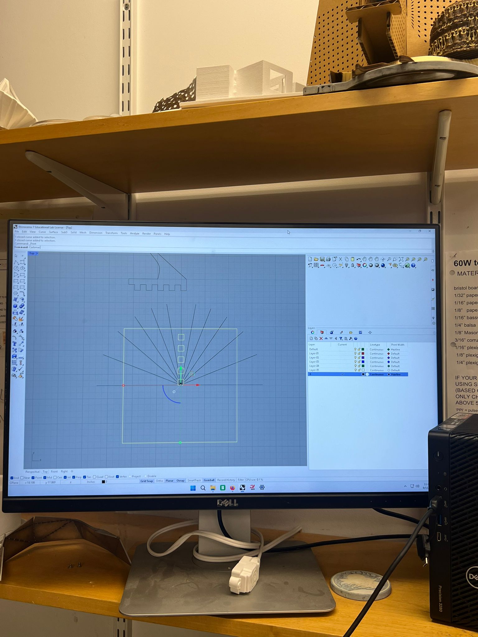
Fusion → Rhino → Laser
Our lab workflow required importing the DXF into Rhino before sending to the laser. I ran into three issues and learned the fixes:
- Scale mismatch: the DXF came in at the wrong size. I used Rhino’s Units and Scale to match caliper measurements, then verified with a 100 mm reference line.
- Grouped/compound curves: some entities were grouped. I used Explode to separate and then Join where continuous cuts were desired.
- Dirty layers/blocks: leftover blocks and layers confused the print driver. I used Purge to clear unused definitions.
After cleanup, I set line weights/colors for cut vs engrave, placed geometry within the bed extents, and printed to the laser driver.
Takeaways: always include a dimensioned reference line in exports; keep a clean layer naming scheme; and sanity-check scale with a ruler before cutting.
Designing the gnomon
For a horizontal dial, the gnomon angle to the plate equals the site latitude: θgnomon = L = 42.3604°. I sized the tab/slot so the same gnomon can plug into either the horizontal or vertical base, making the kit re-configurable.
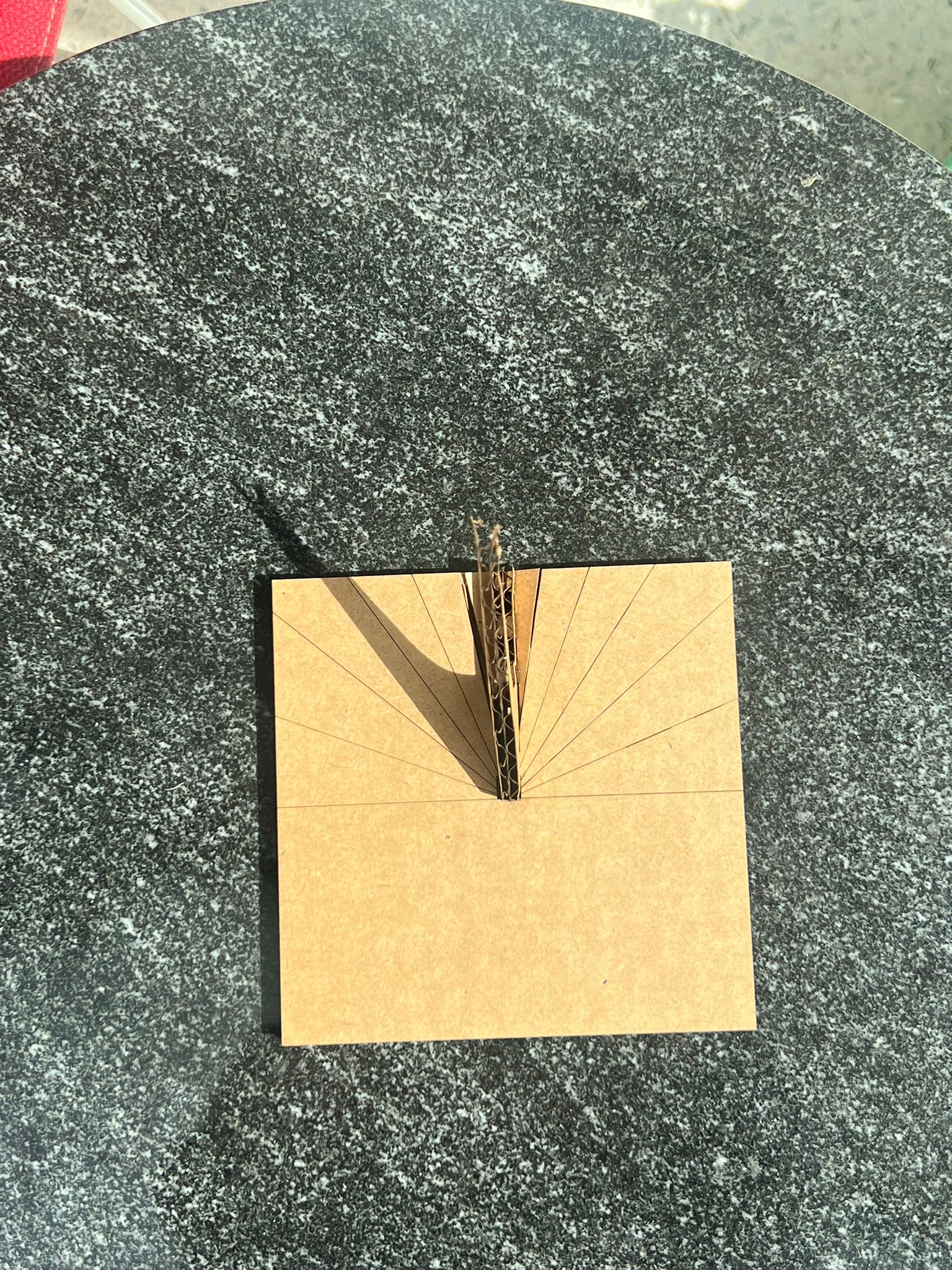
Horizontal sundial
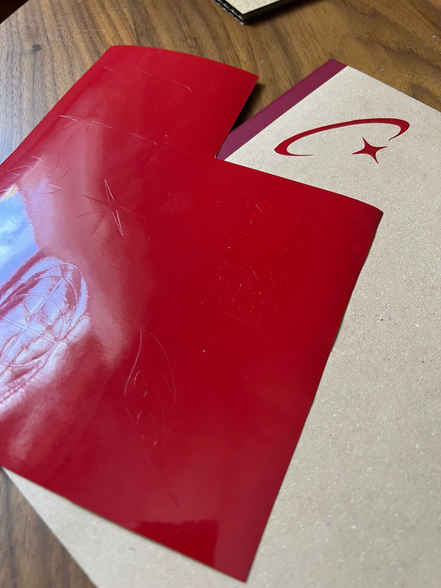
Vinyl cutting notes (mods)
- Open mods in the browser; right-click → “Open in Terminal”, paste the launcher cmd.
- Recommended DPI: 300–600. Higher DPI = smaller image footprint in mods.
- Force defaults to 50 g; good starting range: 80–90 g (too high tears, too low won’t cut).
- Set origin at the blade position; you can also set origin in the UI (default bottom-left) → then “Send to device”.
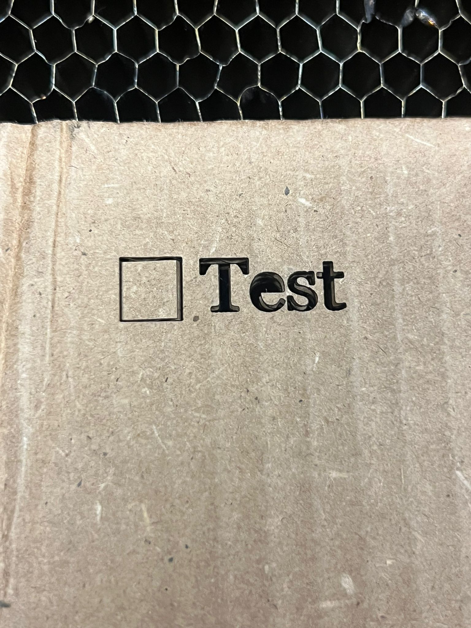
Takeaways: bigger source images preserve small detail; force ~85 g worked best for my material; always test-cut a tiny star first.

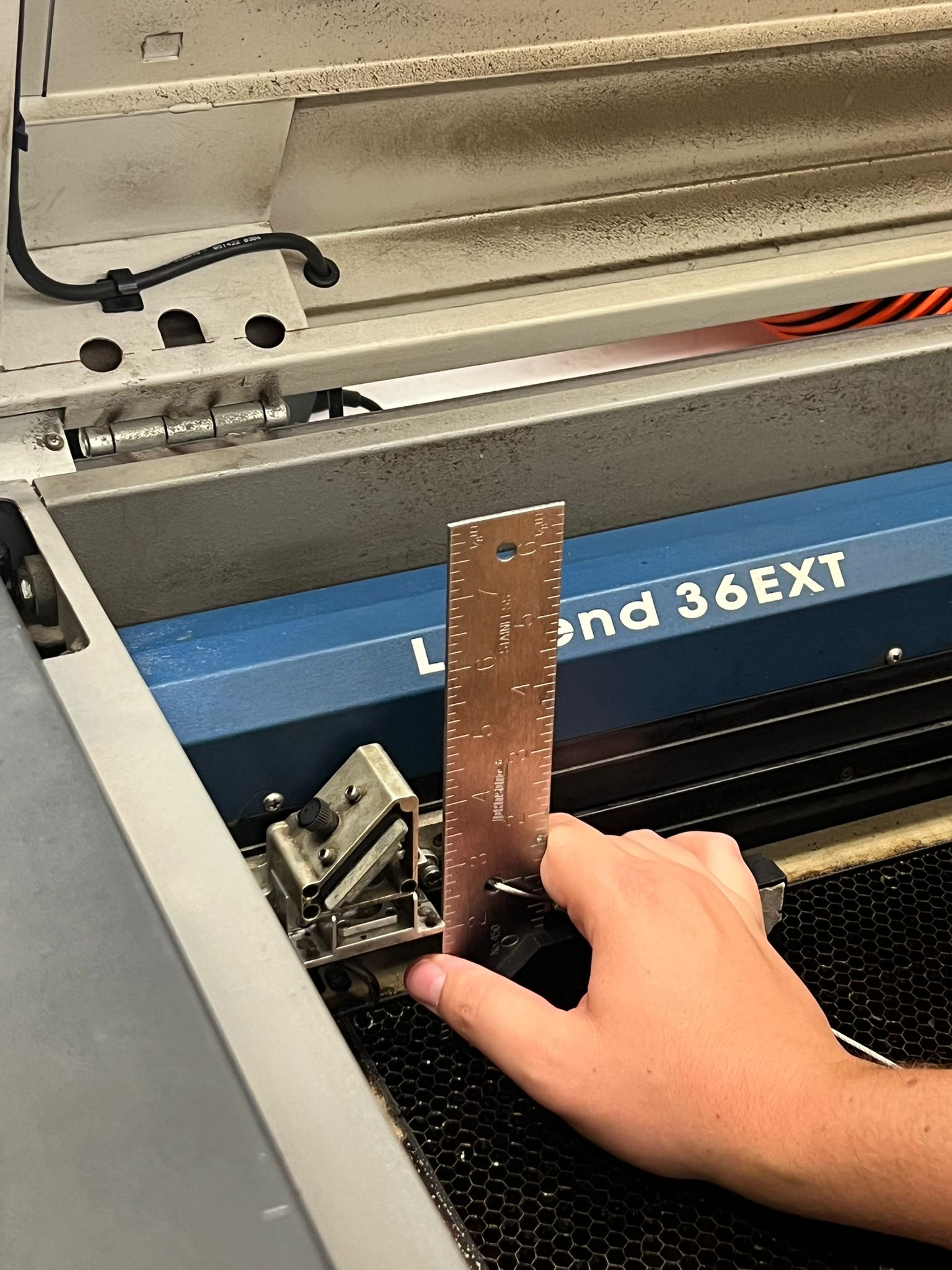
Laser cutting notes
Group assignment: characterize focus, power, speed, frequency, kerf, and joint clearance.
- Measure stock thickness precisely (calipers). Example cardboard: ~6.2 mm.
- Kerf observed ≈ 0.10 mm (verify on your machine/material).
- Material must be flat for consistent focus; warped sheets vary focal distance.
- Set bed height so the focus gauge reads correctly (e.g., 2″ + material thickness if required by your tool).
- Vector cutting “hairline” set by your print driver; still calibrate with kerf tests.
- Start with provided presets for your machine/material, then iterate. Example: speed 30, power 25, freq 500 Hz; adjust speed (e.g., 28) as needed.
- Scale checks: compare printed window scale vs model scale; keep design units consistent.
Takeaways: record every cut setting next to the sample; label your kerf combs; if the fit is “perfect” today, it may be loose tomorrow—re-test on new stock.
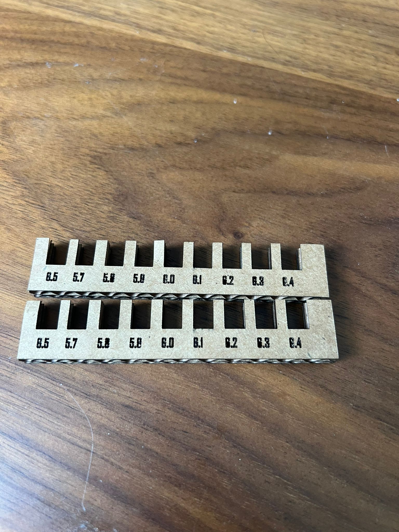
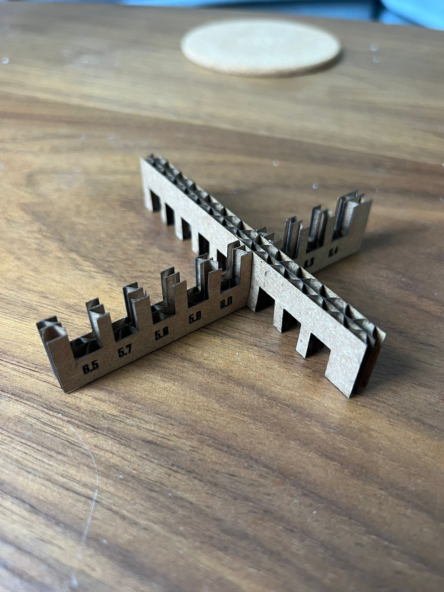
Image gallery
Selected process photos (compressed for web):