individual assignment
First, as most weeks, I started by brainstorming. I’ve never done embedded programming, so the hill to climb felt steep. I’d love to make something useful for my final project, but that’s a big leap, so I started small: understand the board, build confidence with soldering, and get a minimal program interacting with the outside world.
building a board
Below is a snapshot of the components I was working with,
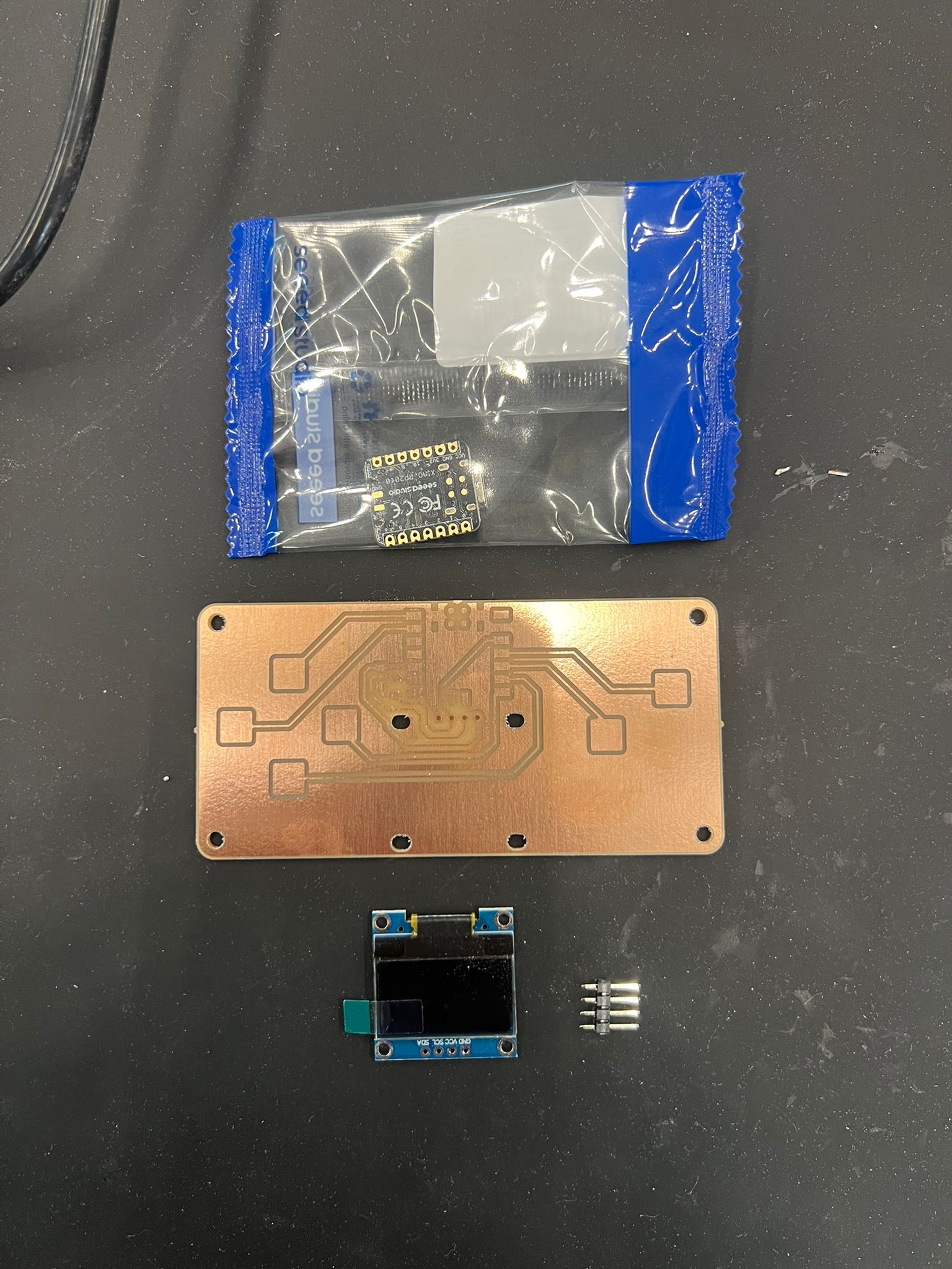
We started with a microcontroller, a screen, a board with capacitance buttons and two 1000 Ohm resistances. Alone, hoewever, these weren't much use, they had to be soldered.
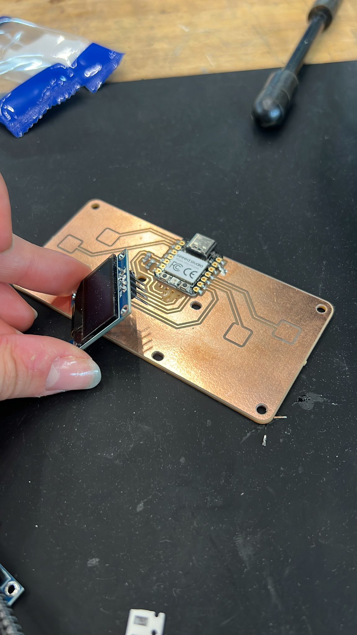
fixing the broken board
After our first soldering attempt, we faced an issue as the screen broke off and took some of the copper lining from the board with it. To debug, our trusty TA QUentin came to the rescue and 3D rinted a holder for the screen. This was just the mechanical support we needed.
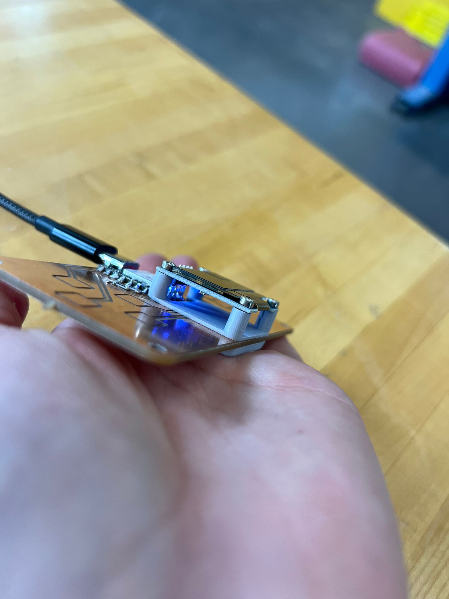
Here's a snapshot of the holder on the board! Thank you Quentin!
Because a picture is worth a thousand words, a video is worth even more (as long as its compressed). Here's a little video of me soldering my board!
testing the microcontroller
ALl put together, we used the usb-c connection to speak with the controller. Thankfully, it seemed the connections were good because it flashed as factory settings would have us expect! This let us quickly check that the board was actually alive and responding to uploads over USB.
After confirming the basics, I moved on to testing the peripherals. Using Quentin’s QPAD-XIAO Arduino code, we verified that both the OLED display and the keypad matrix were functional. The Arduino sketch initializes the display driver and maps the key scanning routine, so we could immediately see whether pixels lit up correctly and if button presses registered in the serial monitor.
Running this known-good firmware was very helpful: instead of debugging both hardware and my own new code at the same time, I could first prove that the hardware itself was soldered correctly and that all traces were making contact. Once the screen displayed the expected test UI "hello world" and the keys produced the right serial output, I was confident the board was ready for my own experiments.
browsing the microcontroller datasheet
Before writing my own code, I spent time browsing the datasheet and technical documentation for the Seeed XIAO RP2040 microcontroller. In particular, I looked up the GPIO pin mapping, USB capabilities, and ADC inputs, since these directly affected how I could scan the keypad, drive the OLED display, and seed randomness for my program.
The RP2040 documentation was especially helpful in understanding how USB device functionality is implemented, which later enabled me to experiment with USB HID media key communication. Reading the datasheet made it much clearer what was handled by hardware, what required firmware support, and what libraries abstracted away.
coming up with my own code
I extended the test into a simple interaction: button press cycles through states and prints structured logs (timestamped) over serial. Next step: implement a “Magic Eight Ball” variant that selects from 10 responses on any button press and displays via OLED + serial.
the Magic 8-Ball
With the display and keypad verified using Quentin’s reference firmware, I wrote a small sketch that turns the QPAD into a Magic 8-Ball: pressing any key selects a random answer from a list of ten phrases, shows it on the OLED, and logs it to Serial for easy capture.
How it works
- Key detection: reuse the matrix scan; a rising “pressed” edge triggers the action.
- Randomness: seed the PRNG once in
setup()from a noisy source (e.g.,analogRead(A0)) XORmillis(), then pickidx = random(0, 10). - Render: clear the OLED buffer, print the chosen string (wrapped), optionally blink an LED, and also
Serial.println()it. - Debounce: ignore further scans until all keys are released or a short cooldown elapses.
Answer set
Ten short phrases that fit cleanly on the OLED:
- It is certain
- Ask again
- Outlook good
- Doubtful
- Yes
- No
- Concentrate
- Reply hazy
- Very likely
- Try later
Step-by-step flow
- Seed:
randomSeed(analogRead(A0) ^ millis()); - Scan: iterate columns, read rows; on first press → proceed.
- Select:
int idx = random(0, 10); - Display: clear, print
answers[idx], update display. - Log:
Serial.println(answers[idx]);(timestamp optional). - Debounce: wait for release or a 200–300 ms cooldown.