Week 5: electronics design
Part I: PCB design
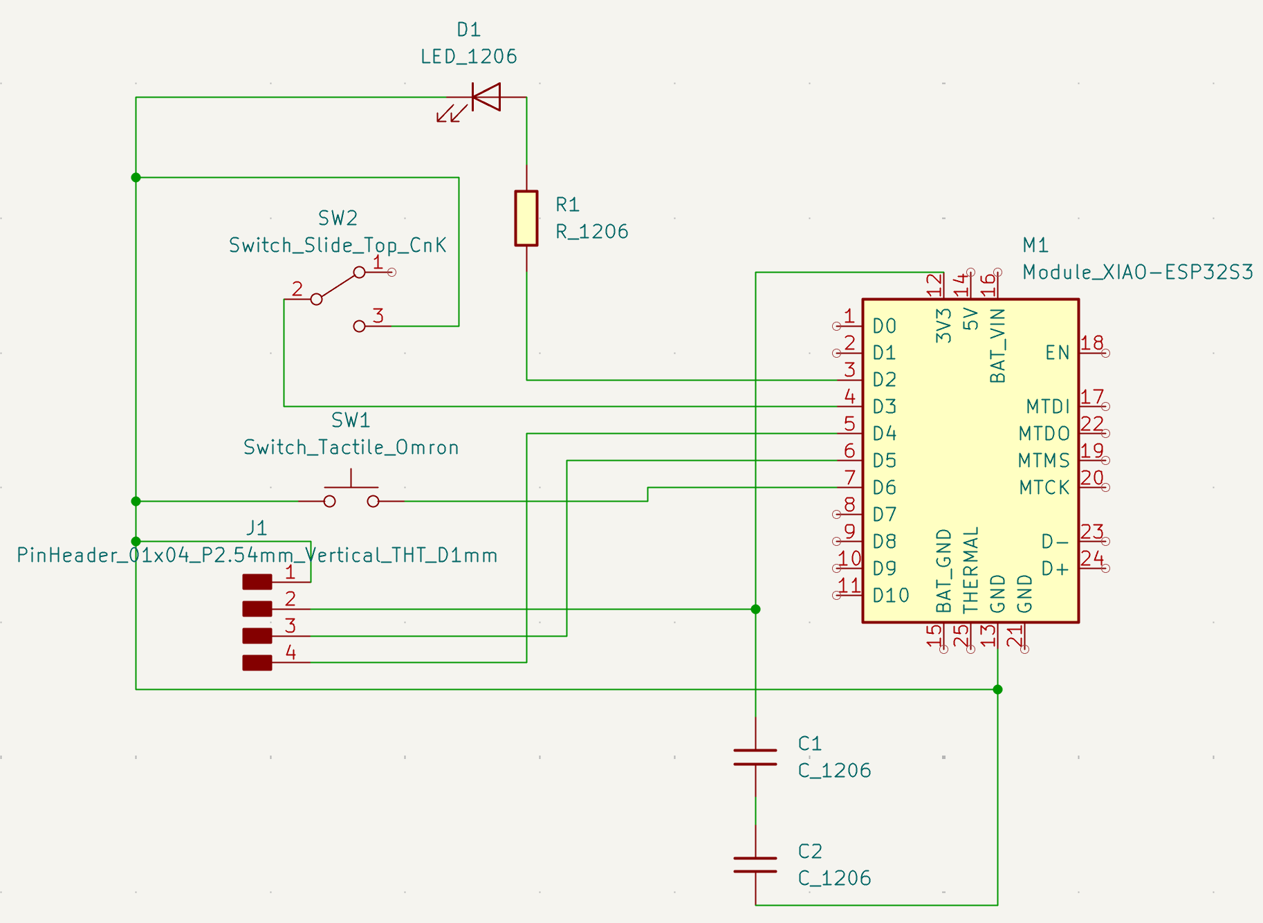
I used KiCAD to design a PCB with the XIAO ESP32S3 Sense. This microcontroller has a camera that I want to use for the posture/face detection feature of my final project. Here is the datasheet. I also incorporated several switches, an LED, and a small OLED display (like the one used on the Q-PAD) to the design. I relied a lot on Gemini this week for help in designing the PCB schematics and explaining acronyms/concepts like SDA/SPI/3V3. I had initially wanted to also add a motor driver but realized the power requirements might be too much with the OLED display and camera and to save the motor for future iteration of the board.
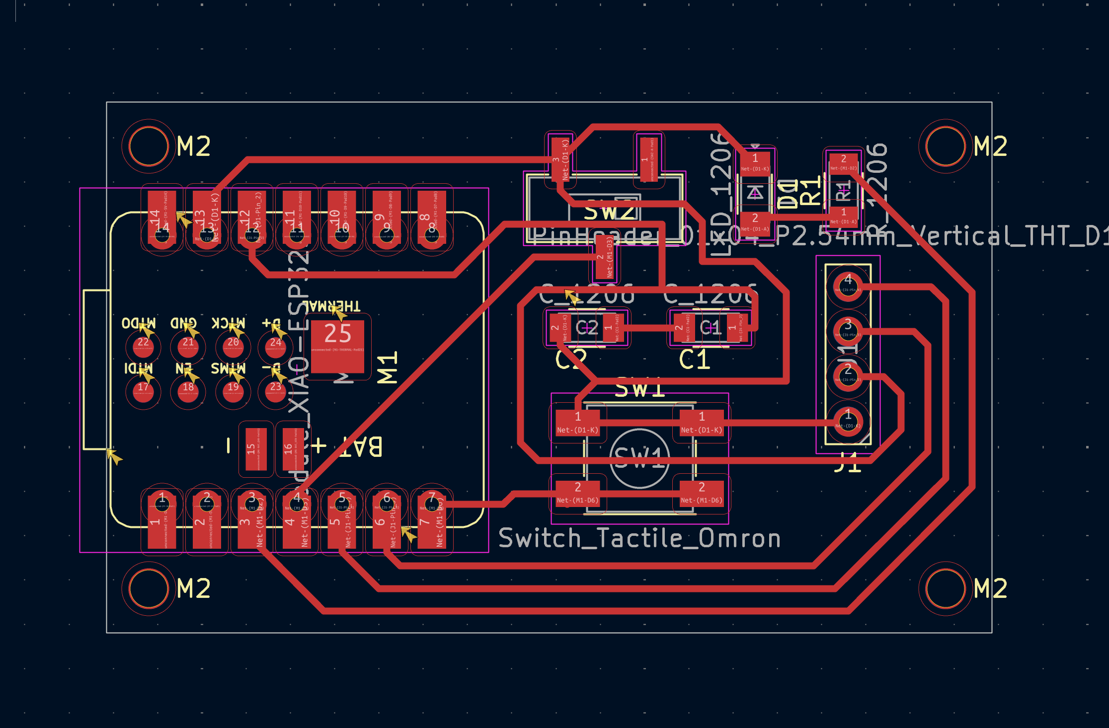
Because the ESP32 is a more expensive controller, I want to add detachable sockets to reuse the ESP32 for other iterations of the PCB design. However, I did't see 7-pin sockets in the fab footprint library. After talking to Alfonso and Alan, I think I can use through pin sockets, which do not need to change the design of the board.
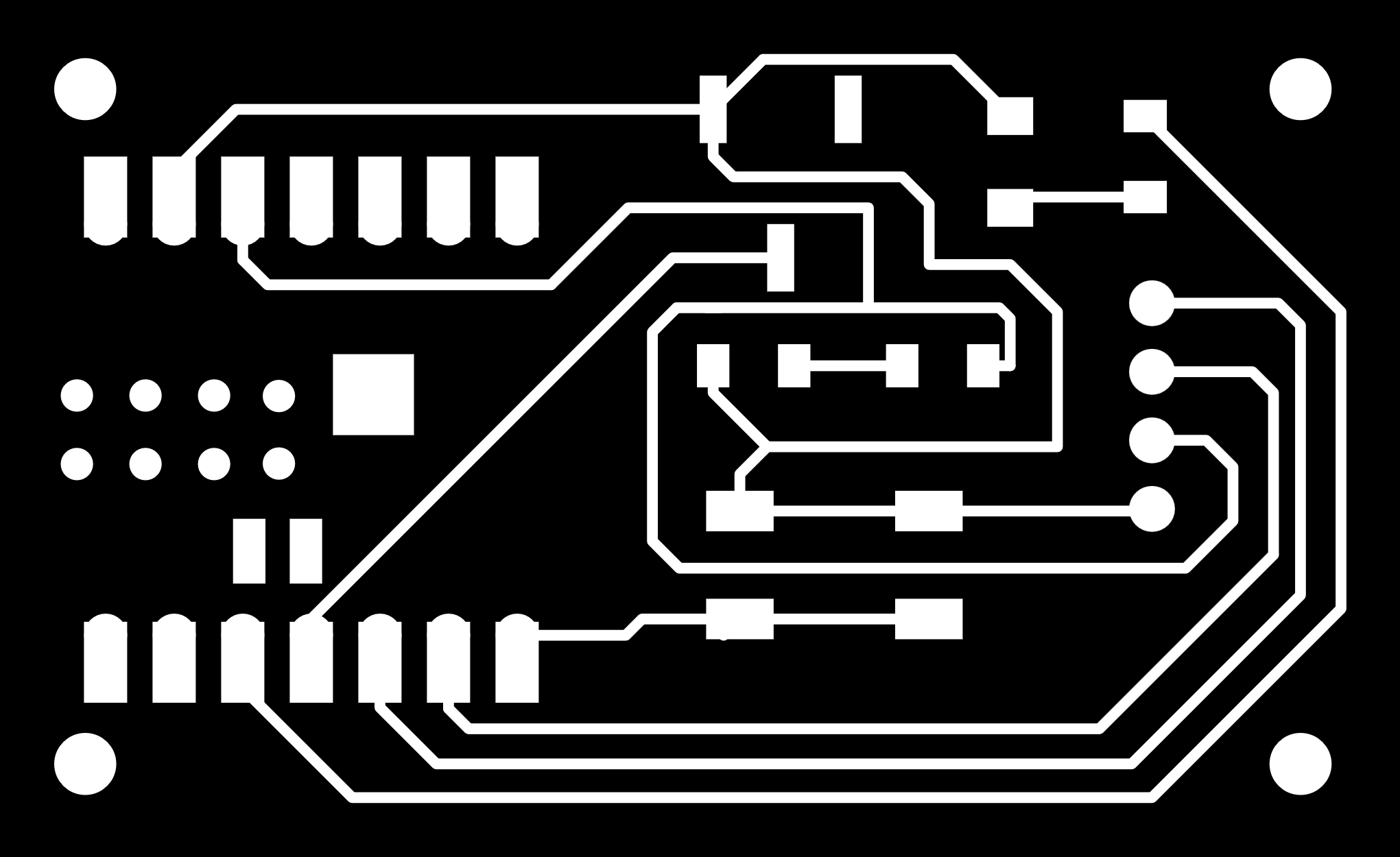
I used the Gerber2Img tool to convert the gerber file to black and white png image.
Part II: test equipment
I missed the slack message about the test equipment session so I bought a multimeter to play around with the Q-Pad and read articles on logic analyzers, oscilloscope, and variable power supple.