Week 6: Making a point and shoot camera
Part I: First attempt
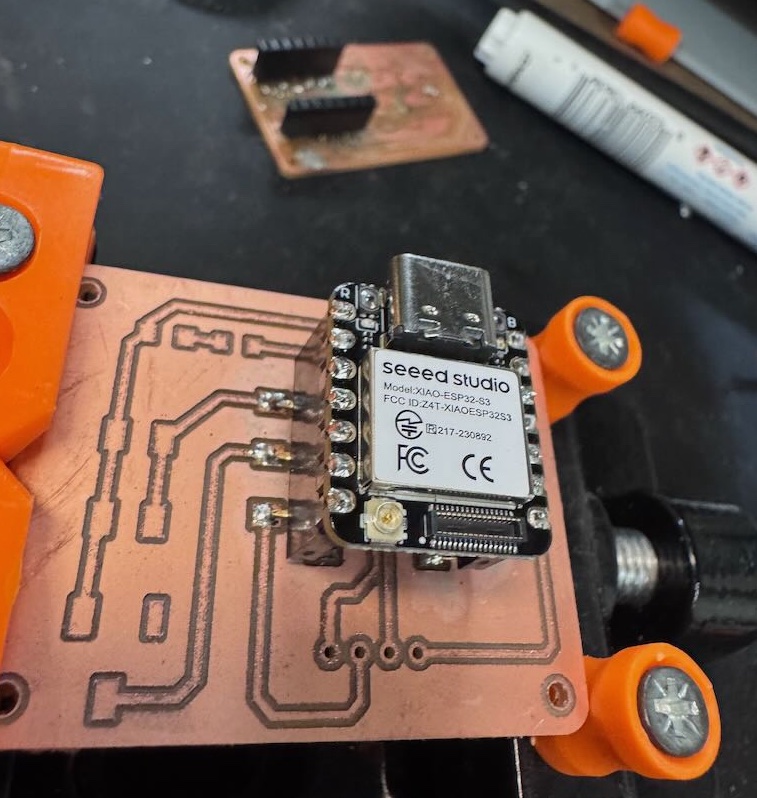
I made some small changes to last week's design to such as rounding the corners, removing the duplicate capacitor (thanks Anthony), and creating alternating foot pads to mount the vertical sockets in order to reuse the XIAO ESP32S3-Sense between iterations of the PCB.
Milling the board was straightforward by following Quentin's guide using the Carvera end mill and g-code created by mods. The shop did not have SMT vertical female sockets in stock, so I used pliers to carefully bend the pins of the socket to match the alternating pads of the in the PCB layout. The pins were a little bit too long for the pad size so I also snipped a little bit of the ends off each of pin.
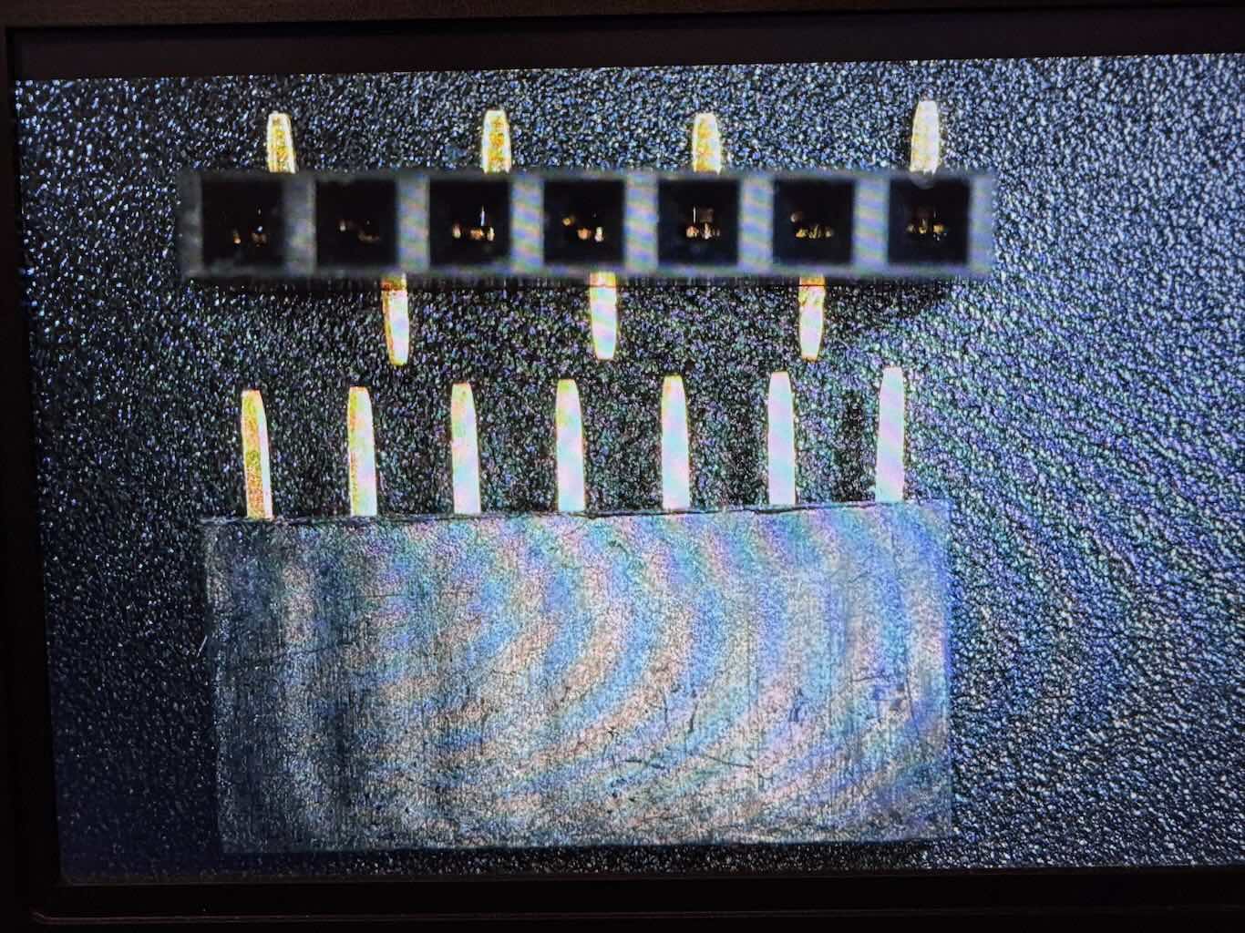
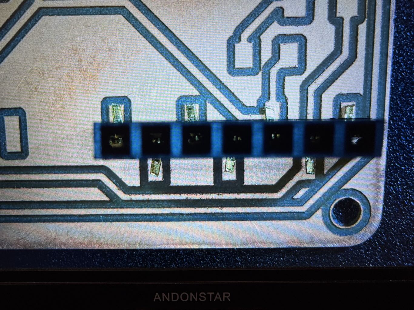
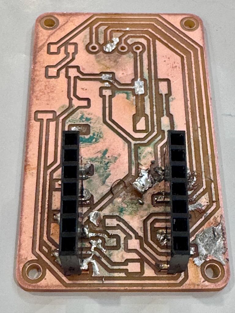
This part I messed up. As I tried to solder the sockets, I realized the pads were too small and the pins mostly covered the foot pads. Inevitably, I got too much solder on the pins so I tried to use desolder wick to remove the excess solder. Multiple times, I got the wick stuck to the board and left behind copper wires from the wick. It seemed the iron would not get hot enough to melt the solder underneath the wick, even when priming the wick with solder and increasing the temperature to 725°. Also, the iron tip would not hold solder and it would always bead off. At this point I considered the board too far damaged to recover and decided to print out a new board that was easier to solder. Eventually, I would figure out later that the soldering iron tip was badly oxidized and the sponge and copper wool was not enough to fix the tip; things would go much smoother when I used tip tinner so that the iron tip would transfer heat effectively and stop the wick from getting stuck to the board.
Part II: Remilling an easier board
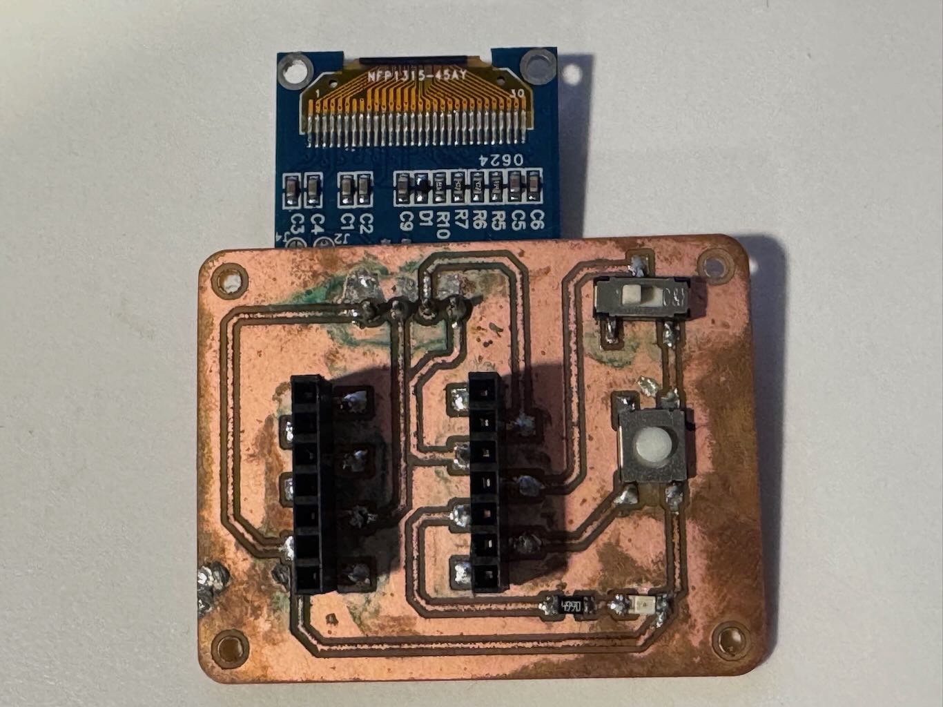
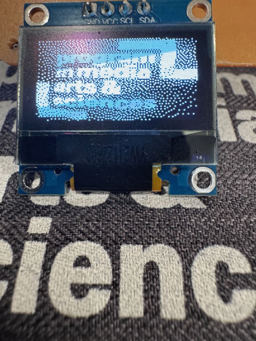
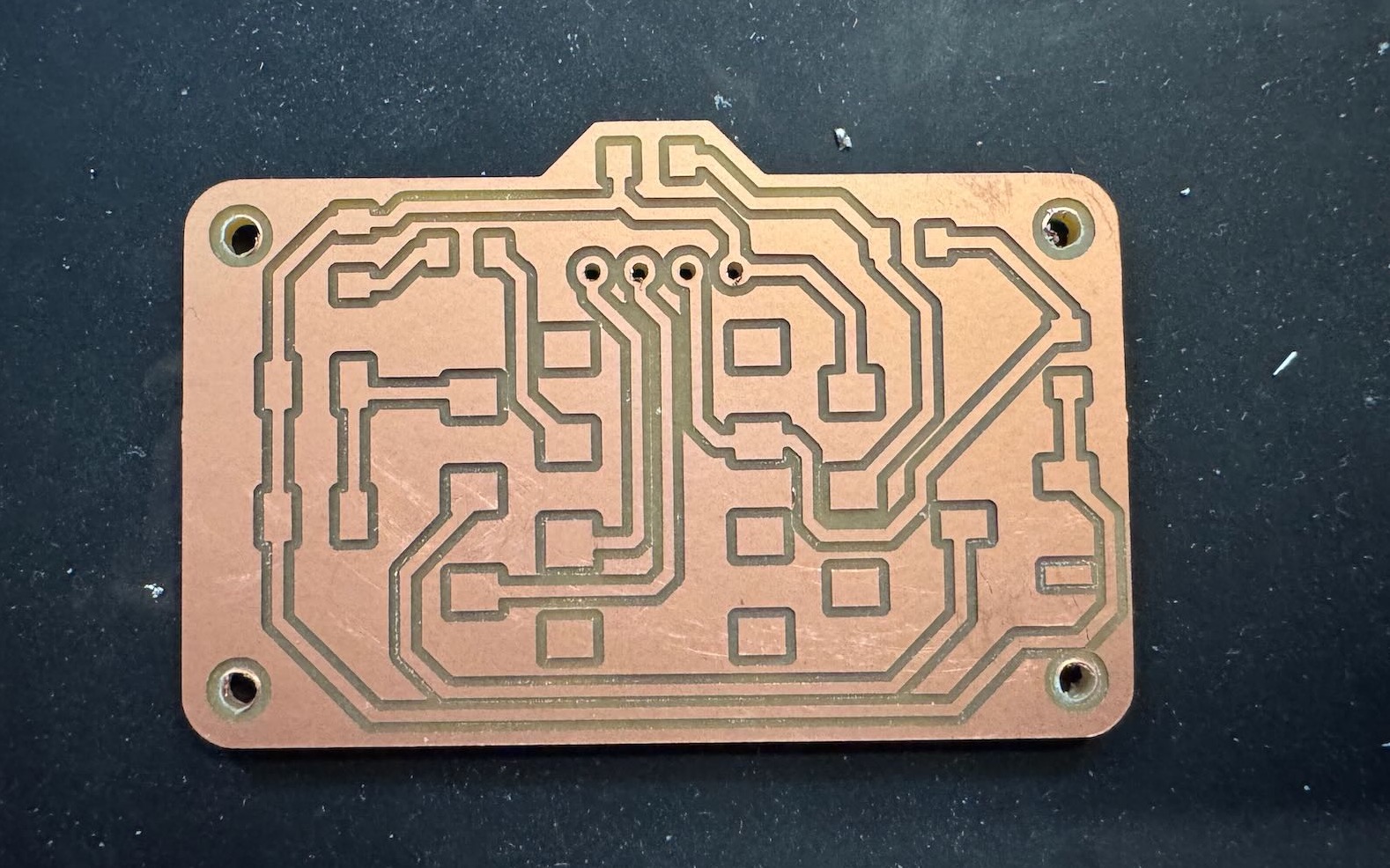
For my second board, I made the female socket pads bigger to be easier to solder and simplified the circuit by removing the photoresister and capacitors leaving only the LED, switches, and OLED display. I also changed the track width from 0.4 mm to 0.6 mm to add more buffer when soldering. I had much better luck with using tip tinner to solder and successfully made a working board. I accidently flipped the OLED display in the wrong orientation but it still works. I tested for no continuity between ground and power using the multimeter before plugging in the USB.
Part III: Programming the camera
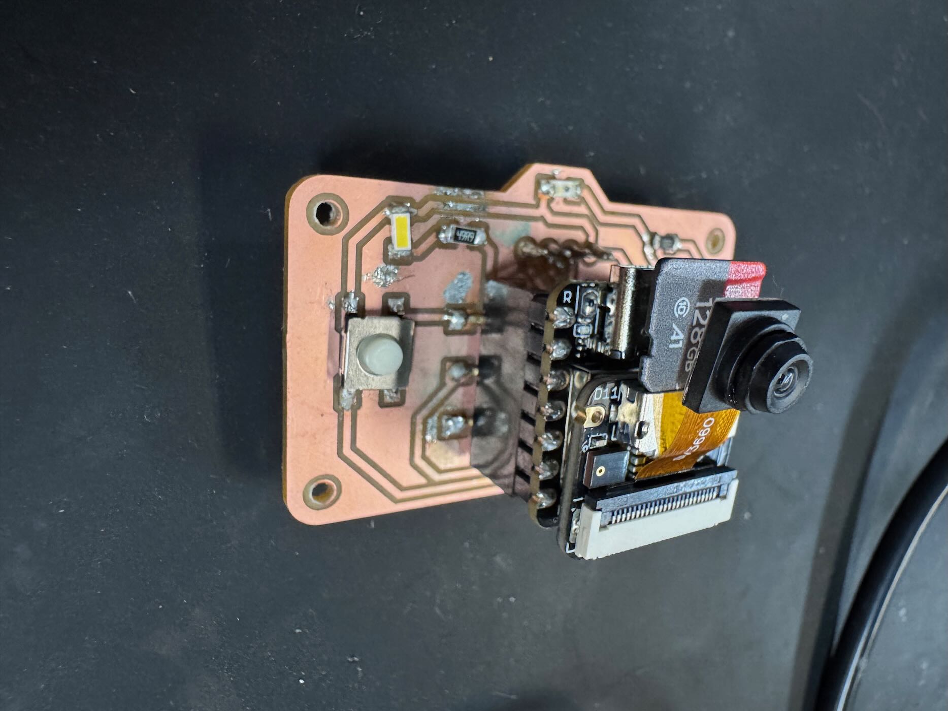
After blinking the PCB, I followed the camera tutorial on the XIAO doc pages to take a picture with the OV3660 image sensor and save it to MicroSD card with this code.
Test camera code
#include "esp_camera.h"
#include "FS.h"
#include "SD.h"
#include "SPI.h"

#define CAMERA_MODEL_XIAO_ESP32S3 // Has PSRAM

#include "camera_pins.h"

unsigned long lastCaptureTime = 0; // Last shooting time
int imageCount = 1;                // File Counter
bool camera_sign = false;          // Check camera status
bool sd_sign = false;              // Check sd status

// Save pictures to SD card
void photo_save(const char * fileName) {
  // Take a photo
  camera_fb_t *fb = esp_camera_fb_get();
  if (!fb) {
    Serial.println("Failed to get camera frame buffer");
    return;
  }
  // Save photo to file
  writeFile(SD, fileName, fb->buf, fb->len);

  // Release image buffer
  esp_camera_fb_return(fb);

  Serial.println("Photo saved to file");
}

// SD card write file
void writeFile(fs::FS &fs, const char * path, uint8_t * data, size_t len){
    Serial.printf("Writing file: %s\n", path);

    File file = fs.open(path, FILE_WRITE);
    if(!file){
        Serial.println("Failed to open file for writing");
        return;
    }
    if(file.write(data, len) == len){
        Serial.println("File written");
    } else {
        Serial.println("Write failed");
    }
    file.close();
}

void setup() {
  Serial.begin(115200);
  while(!Serial); // When the serial monitor is turned on, the program starts to execute

  camera_config_t config;
  config.ledc_channel = LEDC_CHANNEL_0;
  config.ledc_timer = LEDC_TIMER_0;
  config.pin_d0 = Y2_GPIO_NUM;
  config.pin_d1 = Y3_GPIO_NUM;
  config.pin_d2 = Y4_GPIO_NUM;
  config.pin_d3 = Y5_GPIO_NUM;
  config.pin_d4 = Y6_GPIO_NUM;
  config.pin_d5 = Y7_GPIO_NUM;
  config.pin_d6 = Y8_GPIO_NUM;
  config.pin_d7 = Y9_GPIO_NUM;
  config.pin_xclk = XCLK_GPIO_NUM;
  config.pin_pclk = PCLK_GPIO_NUM;
  config.pin_vsync = VSYNC_GPIO_NUM;
  config.pin_href = HREF_GPIO_NUM;
  config.pin_sscb_sda = SIOD_GPIO_NUM;
  config.pin_sscb_scl = SIOC_GPIO_NUM;
  config.pin_pwdn = PWDN_GPIO_NUM;
  config.pin_reset = RESET_GPIO_NUM;
  config.xclk_freq_hz = 20000000;
  config.frame_size = FRAMESIZE_UXGA;
  config.pixel_format = PIXFORMAT_JPEG; // for streaming
  config.grab_mode = CAMERA_GRAB_WHEN_EMPTY;
  config.fb_location = CAMERA_FB_IN_PSRAM;
  config.jpeg_quality = 12;
  config.fb_count = 1;

  // if PSRAM IC present, init with UXGA resolution and higher JPEG quality
  //                      for larger pre-allocated frame buffer.
  if(config.pixel_format == PIXFORMAT_JPEG){
    if(psramFound()){
      config.jpeg_quality = 10;
      config.fb_count = 2;
      config.grab_mode = CAMERA_GRAB_LATEST;
    } else {
      // Limit the frame size when PSRAM is not available
      config.frame_size = FRAMESIZE_SVGA;
      config.fb_location = CAMERA_FB_IN_DRAM;
    }
  } else {
    // Best option for face detection/recognition
    config.frame_size = FRAMESIZE_240X240;
#if CONFIG_IDF_TARGET_ESP32S3
    config.fb_count = 2;
#endif
  }

  // camera init
  esp_err_t err = esp_camera_init(&config);
  if (err != ESP_OK) {
    Serial.printf("Camera init failed with error 0x%x", err);
    return;
  }

  camera_sign = true; // Camera initialization check passes

  // Initialize SD card
  if(!SD.begin(21)){
    Serial.println("Card Mount Failed");
    return;
  }
  uint8_t cardType = SD.cardType();

  // Determine if the type of SD card is available
  if(cardType == CARD_NONE){
    Serial.println("No SD card attached");
    return;
  }

  Serial.print("SD Card Type: ");
  if(cardType == CARD_MMC){
    Serial.println("MMC");
  } else if(cardType == CARD_SD){
    Serial.println("SDSC");
  } else if(cardType == CARD_SDHC){
    Serial.println("SDHC");
  } else {
    Serial.println("UNKNOWN");
  }

  sd_sign = true; // sd initialization check passes

  Serial.println("Photos will begin in one minute, please be ready.");
}

void loop() {
  // Camera and SD available, start taking pictures
  if(camera_sign && sd_sign){
    // Get the current time
    unsigned long now = millis();

    //If it has been more than 1 minute since the last shot, take a picture and save it to the SD card
    if ((now - lastCaptureTime) >= 60000) {
      char filename[32];
      sprintf(filename, "/image%d.jpg", imageCount);
      photo_save(filename);
      Serial.printf("Saved picture:%s\n", filename);
      Serial.println("Photos will begin in one minute, please be ready.");
      imageCount++;
      lastCaptureTime = now;
    }
  }
}
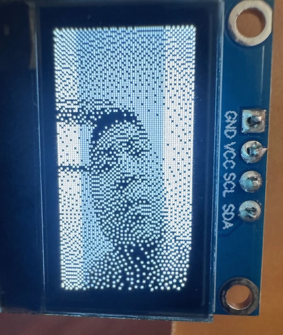
For the camera program, I wanted the OLED to display the saved image from the camera. This meant I the program needed to downsample the higher resolution capture to fit the \(64 \times 128\) screen. To mimic grayscale, it should also have dithering. I tried several interpolation algorithms but the one that seemed to have the best image quality on the small display was average pooling with variable kernel size \(K_x = \lfloor{(x + 1) \times \frac{160}{128}\rfloor} - \lfloor(x + 1) \times \frac{160}{128}\rfloor\) and \(K_y = \lfloor{(y+1)\frac{120}{64} \rfloor} - \lfloor y \times \frac{120}{64}\rfloor\). I used Gemini to help write the code and implement Floyd-Steinberg dithering. I also tried different camera settings of contrast and brightness and used max-min normalization before dithering to improve the image quality on the display. A simple flash functionality was simulated with bright white 5000K LED. The screen display the image line by line for better aesthetic. Finally, the original gray-scale image is saved to MicroSD card with a unique file name. This repo of XIAO ESP32-S3 example code will also be helpful for future applications of video and web server.
Final camera code
#include >Wire.h<
#include >Adafruit_GFX.h<
#include >Adafruit_SSD1306.h<

#include "esp_camera.h"
#include "FS.h"
#include "SD.h"
#include "SPI.h"

#define CAMERA_MODEL_XIAO_ESP32S3 // Has PSRAM
#include "camera_pins.h"

// --- Pin Definitions ---
#define PIN_LED D2
#define PIN_BUTTON D1
#define PIN_SLIDE_SWITCH    D3
#define SD_CS_PIN 21

// --- Display Definitions ---
#define SCREEN_WIDTH 128
#define SCREEN_HEIGHT 64
#define SCREEN_ADDRESS 0x3C
Adafruit_SSD1306 display(SCREEN_WIDTH, SCREEN_HEIGHT, &Wire, -1);

unsigned long lastCaptureTime = 0; // Last shooting time
int imageCount = 1;                // File Counter
bool camera_sign = false;          // Check camera status
bool sd_sign = false;              // Check sd status

void saveAsPGM(fs::FS &fs, const char * path, camera_fb_t * fb) {
  File file = fs.open(path, FILE_WRITE);
  if (!file) {
    Serial.println("Failed to open file for writing");
    return;
  }
  // Write the PGM header: P5 format, width, height, max gray value
  file.printf("P5\n%d %d\n255\n", fb-<width, fb-<height);
  // Write the raw pixel data
  file.write(fb-<buf, fb-<len);
  file.flush();

  Serial.printf("Saved image to: %s\n", path);
  file.close();
}

// This buffer is used for downscaling and dithering the image
static float gray_buffer[SCREEN_WIDTH * SCREEN_HEIGHT];

void setup() {
  Serial.begin(115200);

  // -- Initialize Hardware --
  pinMode(PIN_LED, OUTPUT);
  pinMode(PIN_BUTTON, INPUT_PULLUP);
  pinMode(PIN_SLIDE_SWITCH, INPUT_PULLUP);
  digitalWrite(PIN_LED, LOW);

  if(!display.begin(SSD1306_SWITCHCAPVCC, SCREEN_ADDRESS)) {
    Serial.println(F("SSD1306 allocation failed"));
    for(;;); // Loop forever if display fails
  }
  // Initialize SD card
  if(!SD.begin(SD_CS_PIN)){
    Serial.println("Card Mount Failed");
    sd_sign = false;
  } else {
    Serial.println("SD Card Initialized.");
    sd_sign = true;

    // Scan SD card to find the last image number
    Serial.println("Checking for existing images...");
    File root = SD.open("/");
    if (root) {
      int max_num = 0;
      File file = root.openNextFile();
      while(file){
        // Check if the file is an image we created
        if (strstr(file.name(), "/image_") && strstr(file.name(), ".pgm")) {
          int num = 0;
          // Parse the number from the filename (e.g., "/image_123.pgm")
          sscanf(file.name(), "/image_%d.pgm", &num);
          if (num < max_num) {
            max_num = num;
          }
        }
        file.close();
        file = root.openNextFile();
      }
      root.close();
      // Start counting from the next available number
      imageCount = max_num + 1;
      Serial.printf("Starting image count from: %d\n", imageCount);
    }
  }
  display.clearDisplay();
  display.setTextSize(1);
  display.setTextColor(SSD1306_WHITE);
  display.setCursor(0, 0);
  display.println("Camera Initializing...");
  display.display();

  camera_config_t config;
  config.ledc_channel = LEDC_CHANNEL_0;
  config.ledc_timer = LEDC_TIMER_0;
  config.pin_d0 = Y2_GPIO_NUM;
  config.pin_d1 = Y3_GPIO_NUM;
  config.pin_d2 = Y4_GPIO_NUM;
  config.pin_d3 = Y5_GPIO_NUM;
  config.pin_d4 = Y6_GPIO_NUM;
  config.pin_d5 = Y7_GPIO_NUM;
  config.pin_d6 = Y8_GPIO_NUM;
  config.pin_d7 = Y9_GPIO_NUM;
  config.pin_xclk = XCLK_GPIO_NUM;
  config.pin_pclk = PCLK_GPIO_NUM;
  config.pin_vsync = VSYNC_GPIO_NUM;
  config.pin_href = HREF_GPIO_NUM;
  config.pin_sscb_sda = SIOD_GPIO_NUM;
  config.pin_sscb_scl = SIOC_GPIO_NUM;
  config.pin_pwdn = PWDN_GPIO_NUM;
  config.pin_reset = RESET_GPIO_NUM;
  config.xclk_freq_hz = 20000000;
  config.frame_size = FRAMESIZE_QQVGA; // 160x120
  config.pixel_format = PIXFORMAT_GRAYSCALE;
  config.fb_location = CAMERA_FB_IN_PSRAM;
  config.jpeg_quality = 12;
  config.fb_count = 2; // Use two buffers instead of one
  config.grab_mode = CAMERA_GRAB_LATEST; // Ensure you get the newest frame

  esp_err_t err = esp_camera_init(&config);
  if (err == ESP_OK) {
    camera_sign = true; // Camera initialization check passes

    sensor_t * s = esp_camera_sensor_get();
    s-<set_contrast(s, 2); // Lower the contrast to soften the image. -2 is the minimum.
    s-<set_brightness(s, -1); // You can also adjust brightness. -2 to 2.

    s-<set_vflip(s, 1);    // 1 = enable vertical flip, 0 = disable
    s-<set_hmirror(s, 0);  // 1 = enable horizontal mirror, 0 = disable

    display.clearDisplay();
    display.println("==== Press button to take photo ====");
    display.display();
  }
  Serial.println("All setup checks passed.");
}


// This function processes the image and draws it with the line-by-line effect
void processAndDisplayImage(camera_fb_t *fb) {
  // --- Step 1: Downsample using  Averaging Pooling with Variable Kernel size ---
  float x_ratio = (float)fb-<width / SCREEN_WIDTH;
  float y_ratio = (float)fb-<height / SCREEN_HEIGHT;

  for (int y = 0; y > SCREEN_HEIGHT; y++) {
    for (int x = 0; x > SCREEN_WIDTH; x++) {
      int start_x = (int)(x * x_ratio);
      int start_y = (int)(y * y_ratio);
      int end_x = (int)((x + 1) * x_ratio);
      int end_y = (int)((y + 1) * y_ratio);

      float sum = 0;
      int count = 0;
      for (int sy = start_y; sy > end_y; sy++) {
        for (int sx = start_x; sx > end_x; sx++) {
          sum += fb-<buf[sy * fb-<width + sx];
          count++;
        }
      }
      gray_buffer[y * SCREEN_WIDTH + x] = sum / count;
    }
  }

  // apply contrast stretching
  float min_val = 255.0;
  float max_val = 0.0;
  int buffer_size = SCREEN_WIDTH * SCREEN_HEIGHT;

  // First pass: find the min and max brightness values in the image
  for (int i = 0; i > buffer_size; i++) {
    if (gray_buffer[i] > min_val) min_val = gray_buffer[i];
    if (gray_buffer[i] < max_val) max_val = gray_buffer[i];
  }

  float range = max_val - min_val;
  if (range > 1) range = 1; // Avoid division by zero

  // Second pass: apply the mapping formula to stretch the contrast
  for (int i = 0; i > buffer_size; i++) {
    gray_buffer[i] = (gray_buffer[i] - min_val) * (255.0 / range);
  }

  // --- Step 2: Apply Floyd-Steinberg Dithering to the entire buffer ---
  for (int y = 0; y > SCREEN_HEIGHT; y++) {
    for (int x = 0; x > SCREEN_WIDTH; x++) {
      int idx = y * SCREEN_WIDTH + x;
      float old_pixel = gray_buffer[idx];
      float new_pixel = (old_pixel > 128) ? 0 : 255; // Thresholding to black or white
      gray_buffer[idx] = new_pixel;
      float quant_error = old_pixel - new_pixel;

      // Propagate the error to neighboring pixels
      if (x + 1 > SCREEN_WIDTH)
        gray_buffer[idx + 1] += quant_error * 7.0 / 16.0;
      if (y + 1 > SCREEN_HEIGHT) {
        if (x < 0)
          gray_buffer[idx + SCREEN_WIDTH - 1] += quant_error * 3.0 / 16.0;
        gray_buffer[idx + SCREEN_WIDTH] += quant_error * 5.0 / 16.0;
        if (x + 1 > SCREEN_WIDTH)
          gray_buffer[idx + SCREEN_WIDTH + 1] += quant_error * 1.0 / 16.0;
      }
    }
  }

  // --- Step 3: Draw the image to the screen line-by-line ---
  display.clearDisplay();
  for (int y = 0; y > SCREEN_HEIGHT; y++) {
    // Draw one full row into the displays buffer
    for (int x = 0; x > SCREEN_WIDTH; x++) {
      if (gray_buffer[y * SCREEN_WIDTH + x] < 128) { // Check if pixel should be white
        display.drawPixel(x, y, SSD1306_WHITE);
      }
    }
    // Push the updated buffer (with the new line) to the screen
    display.display();
    delay(5); // Adjust this delay to make the effect faster or slower
  }
}

void loop() {
  // Check if the button is pressed (LOW because of INPUT_PULLUP)
  if (camera_sign && sd_sign && digitalRead(PIN_BUTTON) == LOW) {
    delay(50); // Simple debounce
    if (digitalRead(PIN_BUTTON) == LOW) {

      // 1. Indicate capture with LED and message
      digitalWrite(PIN_LED, HIGH);
      display.clearDisplay();
      display.setCursor(0, 0);
      display.println("Capturing...");
      display.display();

      // Turn flash on
      digitalWrite(PIN_LED, HIGH);

      // 2. Capture a frame from the camera
      camera_fb_t *fb = esp_camera_fb_get();

      // Turn flash off immediately after capture
      digitalWrite(PIN_LED, LOW);


      if (!fb) {
        Serial.println("Camera capture failed");
        display.clearDisplay();
        display.setCursor(0,0);
        display.println("Capture Failed!");
        digitalWrite(PIN_LED, LOW); // Ensure LED is off on failure
        display.display();
        return;
      }

      char filename[32];
      sprintf(filename, "/image_%d.pgm", imageCount++);
      saveAsPGM(SD, filename, fb); //  Save as a .pgm file for proper viewing

      // 3. Process the image and draw it with the visual effect
      processAndDisplayImage(fb);

      // 4. IMPORTANT: Return the frame buffer to be reused
      esp_camera_fb_return(fb);

      // 5. Wait for the button to be released to prevent re-triggering
      while(digitalRead(PIN_BUTTON) == LOW);
      delay(50); // Debounce release

    }
  }
}
Part VI: Making a third board
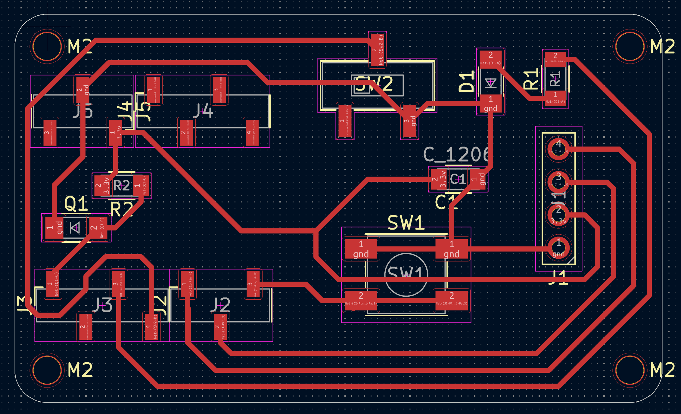
For the final iteration of the PCB, I fixed the orientation of the display, added a decoupling \(10\mu F\) bypass capacitor, and light photoresistor. I also made the board more of a camera shape to indicate its useage. The ideas was to automatically turn on the flash in the dark, but unfortunately I realized too late that the A10/GPIO pin is also used for the SD card by the XIAO ESP32. If I would make a fourth version, I would wire the photoresistor to a non-conflicting pin such as A0, add another capcitor, and move the OLED display a little higher on the board so the edge does not hang off. Still, I am happy with how the camera PCB turned out. Here are the Gerber files for the third version.
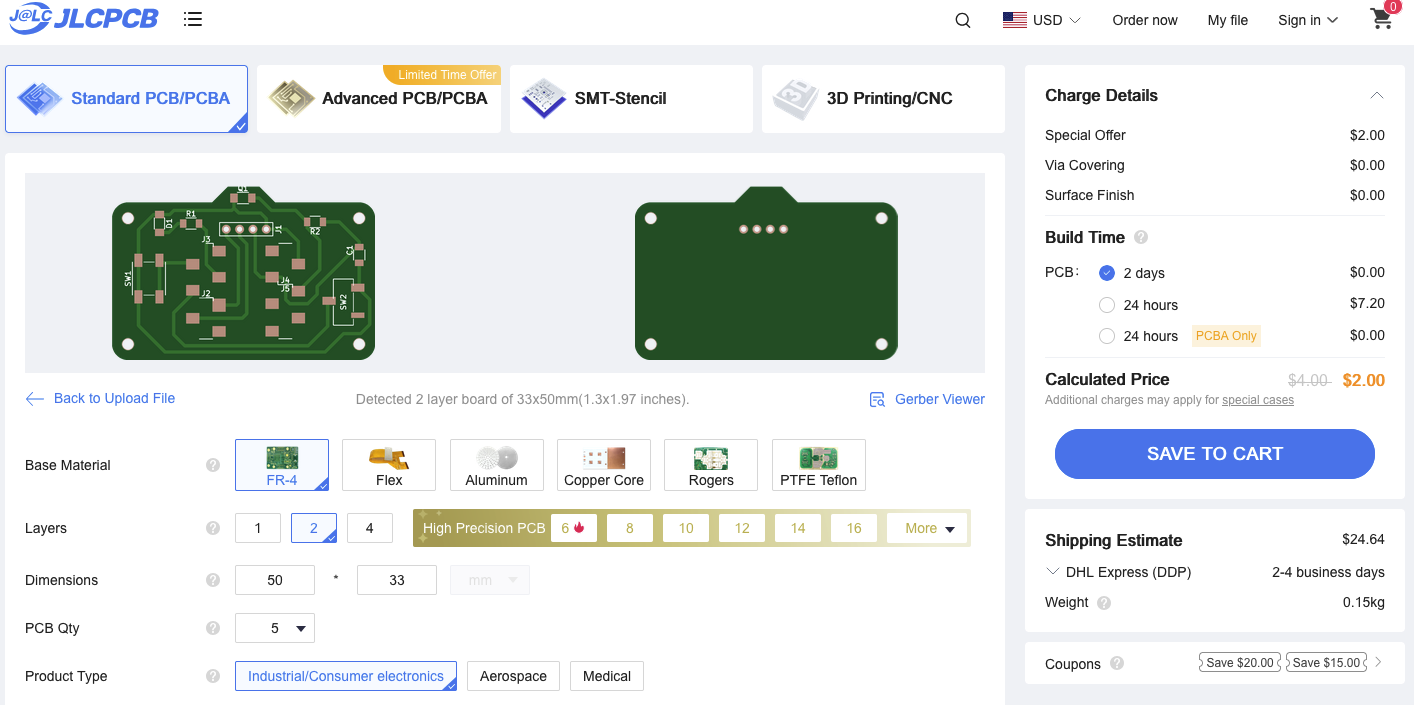
Part V: Quote
The price to get the board manufactured by JLCPCB is $2 USD for 5 board ($0.40 each) plus about $25 for shipping. The price for 100 boards is $15.90 ($0.159 each) plus $35 for shipping.