This week's assignment was to design something to be fabricated using the 3D printer that could not be manufactured subtractively. In order to understand the printer and the design constraints it would impose, it was necessary to complete some tests of its built-in "rules" that impact its precision and flexibility.
Our printers in the EECS shop are the Prusa CORE One with a HFO 0.4 mm nozzle. Here is a link to the device and its specs.
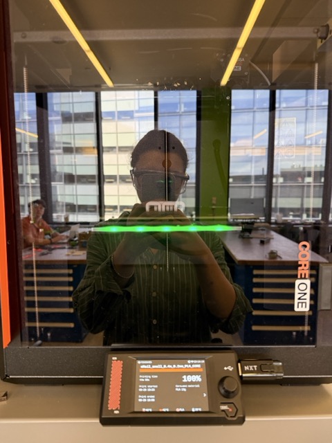
And here is me observing my print inside of one:
Inspired by the Kinematics Link Bodice by Nervous System shown in class, I wanted to print a simple version of chainmail for my assignment this week. This is a (textile? medium? material?) that would be almost impossible to make subtractively.
Design Rules
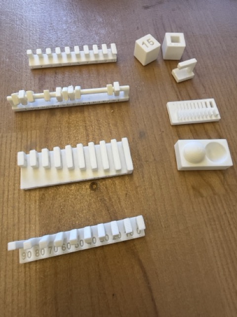
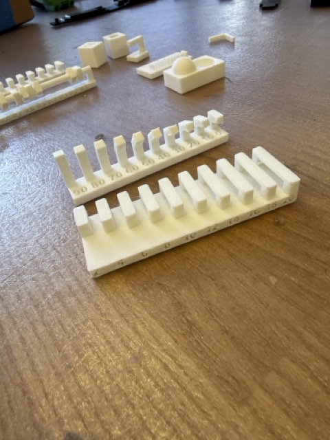
For the group assignment, we printed a set of test objects as kindly summarized by Neil under "design rules" in the class page for this week. We used PLA for the tests. These objects test attributes of the printer's limitations including the following:
Clearance
:
the minimum distance between elements that are supposed to be separate.
Overhang
:
the maximum distance that a 90' horizontal element can extend from its vertical base without support.
Angle
:
the minimum angle (if horizontal is 0' and vertical is 90') that unsupported material can extend without devolving into spaghetti.
Bridging
:
the maximum distance that a horizontal element can extend between two vertical elements without support in between them.
Wall Thickness
:
the minimum thickness of a vertical wall achievable by the nozzle (also printed with tests for the minimum slot size of linear holes in solid printed area).
Dimensions
:
the precision of the 3D printer in executing an object at the desired dimensions.
Surface Quality
:
the degree of track lines visible on a rounded surface.
Linked is a group page with notes from this portion of the assignment.
Below are our prints of all the test objects:
Chainmail consists of small circular or rectangular units that require bridging, and since I wanted mine to have rounded edges, there would also be some angled portions sloping upward. I wanted to make something thin but not thin enough to push the boundaries of the printer.
For my purposes (since I wasn't going to be highly picky about surface texture or dimensions), the most relevant tests were
Angle
and
Overhang
:
I kept these measurements in mind while making my design, although I found the capacities of the printer more than sufficient for what I intended to design-- my project did not push these design rules substantially.
Design Process
Since chainmail consists of small, interlocked shapes in a repeating pattern, it seemed like a good opportunity to advance my parametric design skills. For this reason I chose to implement my design in Fusion this week.
Conveniently, Autodesk Fusion offered a parametric chainmail tutorial on its open-source Instructables website, which was a new resource to me and appears to be an extremely useful one.
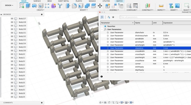
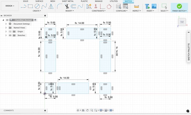
I followed the steps of the tutorial to create a sketch with parameterized dimensions for each component:
And then I learned the process of aligning these dimensions with
Constraints
that maintain key relationships among the components:
Once the sketch was correctly constrained, it was possible to change any parameter without breaking it:
I also learned how to apply parameters and constraints in 3 dimensions, once I extruded components based on the sketch:
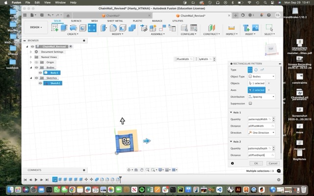
Having produced one link of the chainmail, I used more user-defined parameters to create a "rectangular pattern" of elements with it:
Once these were in place, I needed to move one element so that it would interlock with the others. This I did with more parameters:
And then by repeating the rectangular pattern again, starting with this moved piece, I could create a second set of elements that all interlocked with the first set in the same way.
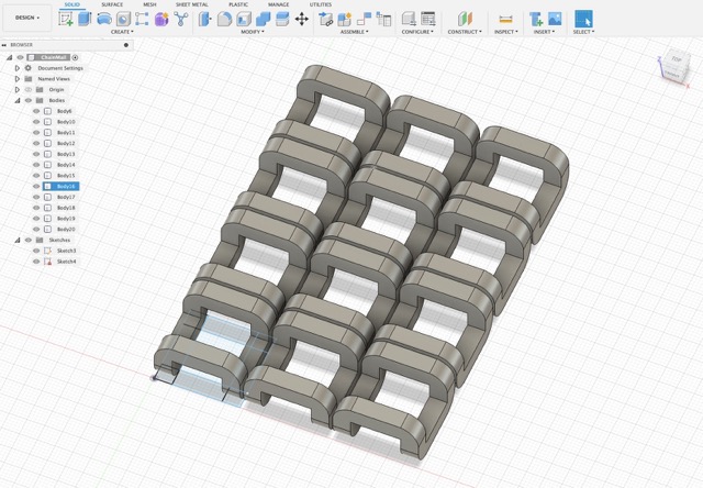
Since the elements were constrained and parameterized all the way through, I was then able to manipulate the whole assembly by changing parameters once both patterns were established:
3D Printing My Version
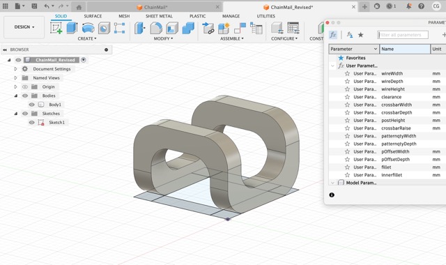
The above version of the chainmail is the precise one directed by the tutorial. In order to make it my own, I added more parameters to fillet all the corners so that they would more closely approximate a circular-link chainmail, and I used existing parameters to modify the scale and proportions of the pattern:
With the design part ready to go, it was time to start printing. I learned from laser cutting week that a small, simple, fast prototype can tell you much of what you need to know before printing a full-scale version, so I started out by exporting a small section of the pattern, parameterized to print relatively big links so that I could see how they worked.
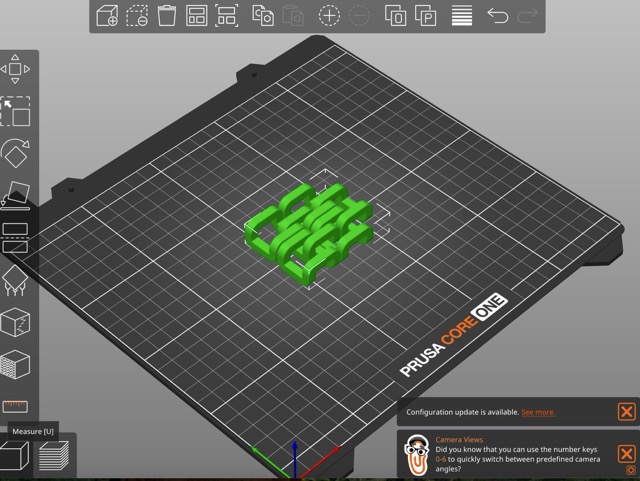
I exported a .stl file of this test section and imported it to the PrusaSlicer app:
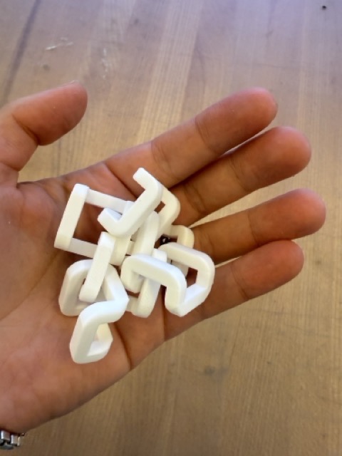
This section only took 45 minutes to print and gave me a sense for how the pattern was working. I found that the elements printed smoothly and the links were solid-- it was quite amazing to pull this out of the printer and find the links inextricably in place.
However, as I suspected the links were too big and far apart, making them prone to collapsing onto one another and creating more of a cluster than a surface. While this is a fun puzzle to rearrange, it is not what I ultimately wanted:
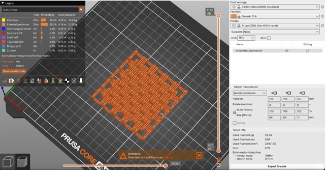
With this in mind, I revised the design by changing parameters to achieve more, smaller, rounder, closer-together links in the chainmail and re-sliced:
This version threw an error in the slicer about lacking support or contact with the bed, which I think is because I created more rounded elements and by making them smaller also reduced the footprint of the print area. However, after consulting EDS lab staff, we decided to give it a try anyway:
The print took about two hours and used about 30 grams of PLA. This version resulted in a chainmail that behaved much more like a fabric or surface!
In future versions, I would try to push the limits of how small and close together the links would be. In the interest of time this week I wanted to avoid any potential challenges with the abilities of the printer but I believe that smaller, more circular, and closer together links would make for a smoother and more unified whole.
3D Scanning
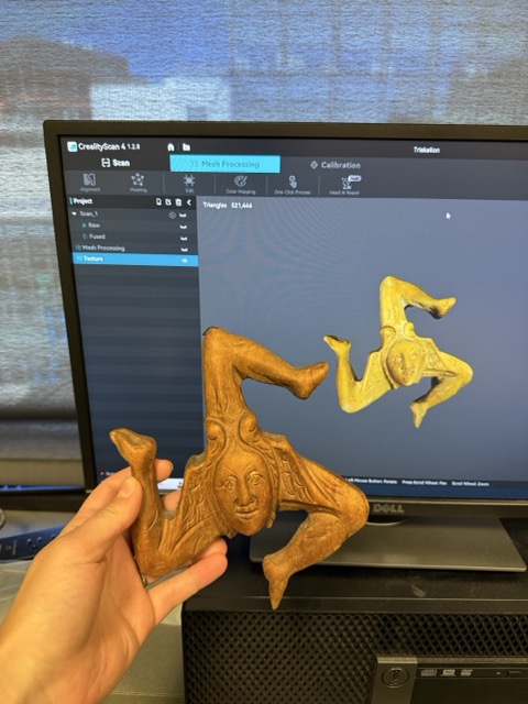
The second part of our assignment this week was to use the 3D scanner to scan an object. I brought in a Sicilian triskelion I had purchased in Venice from a church thrift store.
The scanning machine in the EDS Lab is a Creality Ferret and connects via USB to a computer that runs the corresponding Creality software. We used it with a rotating plate that helps the scanner to access all parts of the object evenly.
As the object rotated, the scanner captured more points on its point cloud:
Once the point cloud was finished (about 2 minutes), the object was mostly visible but had some holes where the scan was occluded, some stray points on the edges of the plate, and a hollow back side. In order to clean and close it up, I used the built-in "mesh" feature in the Creatlity application:
The meshing actually seemed to improve the detail of the original scan. Finally, I noticed there waas a "color" tab in the application and applied true-color to the object. This made it appear more realistic, and more accurate:
Trials and Tribulations
Following are some observations of the process this week, and some challenges or disappointments to record:
This week I found the 3D printing and scanning both quite intuitive.
My only setback was that at first I made the constraints on my parametric model without testing them at each stage, only to find that the finished product was not manipulable in the way I wanted. This was a useful lesson in "spiral development" in that it forced me to start over from the beginning and test all my constraints as I went.
One thing I did not do this week was leverage AI in a meaningful way. After our recitation I felt stunned and somewhat intimidated by the number of possible interventions AI could make. I am still figuring out my own "AI ethic" as it relates to whether I want to prioritize where I fall on the spectrum of learning *how to do the skills of the course* or learning *how to make AI do the skills of the course.*
Learnings and Progress
Below is the delta between where I started on the skills for this week and where I arrived:
I found both printing and scanning this week quite intuitive, though I had never done either one myself before.
Relative to laser-cutting week, I think I learned my lesson this time about fabricating small prototypes before going for a full-size implementation.
I was also happy to take the parametric design principles another step further this week, and to get more comfortable in Fusion while doing so.
Resources and Acknowledgments
Thank you to Anthony for the tutorials as always.
My main online resource this week was the already discussed tutorial via Autodesk, which served as a starting point for my parametric chainmail experiment.
Design Files
Here is my test chainmail .stl and .3mf with .bgcode
Here is my final chainmail .stl and .3mf with .bgcode
And my scanning mesh .stl. The files to apply color are about 100MB uncompressed and another 33MB compressed, so I have not included them here due to upload limits.
 Inspired by the Kinematics Link Bodice by Nervous System shown in class, I wanted to print a simple version of chainmail for my assignment this week. This is a (textile? medium? material?) that would be almost impossible to make subtractively.
 Chainmail consists of small circular or rectangular units that require bridging, and since I wanted mine to have rounded edges, there would also be some angled portions sloping upward. I wanted to make something thin but not thin enough to push the boundaries of the printer.
 I kept these measurements in mind while making my design, although I found the capacities of the printer more than sufficient for what I intended to design-- my project did not push these design rules substantially.
 And then I learned the process of aligning these dimensions with
 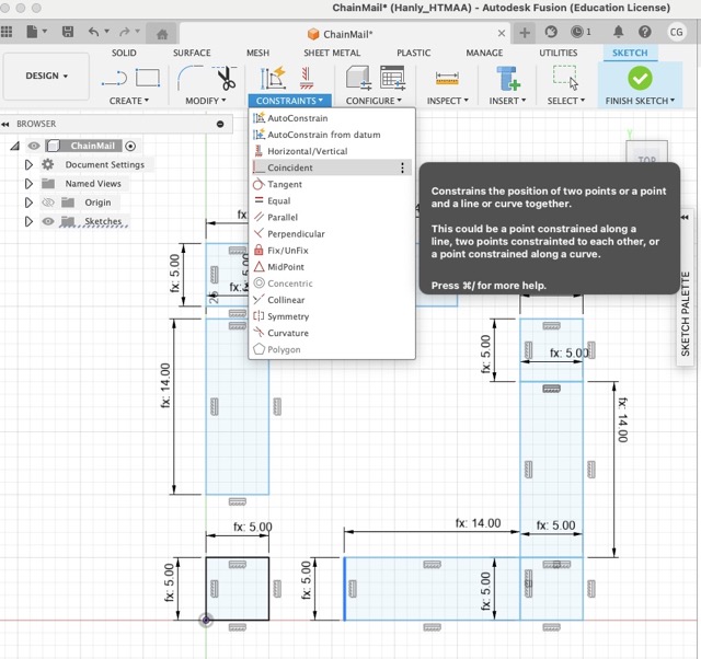 Once the sketch was correctly constrained, it was possible to change any parameter without breaking it:
I also learned how to apply parameters and constraints in 3 dimensions, once I extruded components based on the sketch:
Having produced one link of the chainmail, I used more user-defined parameters to create a "rectangular pattern" of elements with it:
Once the sketch was correctly constrained, it was possible to change any parameter without breaking it:
I also learned how to apply parameters and constraints in 3 dimensions, once I extruded components based on the sketch:
Having produced one link of the chainmail, I used more user-defined parameters to create a "rectangular pattern" of elements with it:
 Once these were in place, I needed to move one element so that it would interlock with the others. This I did with more parameters:
And then by repeating the rectangular pattern again, starting with this moved piece, I could create a second set of elements that all interlocked with the first set in the same way.
Once these were in place, I needed to move one element so that it would interlock with the others. This I did with more parameters:
And then by repeating the rectangular pattern again, starting with this moved piece, I could create a second set of elements that all interlocked with the first set in the same way.
 With the design part ready to go, it was time to start printing. I learned from laser cutting week that a small, simple, fast prototype can tell you much of what you need to know before printing a full-scale version, so I started out by exporting a small section of the pattern, parameterized to print relatively big links so that I could see how they worked.
 This section only took 45 minutes to print and gave me a sense for how the pattern was working. I found that the elements printed smoothly and the links were solid-- it was quite amazing to pull this out of the printer and find the links inextricably in place.
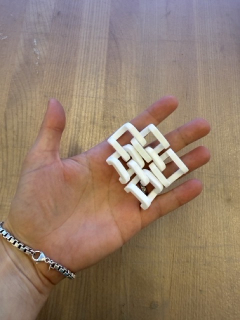 However, as I suspected the links were too big and far apart, making them prone to collapsing onto one another and creating more of a cluster than a surface. While this is a fun puzzle to rearrange, it is not what I ultimately wanted:
 With this in mind, I revised the design by changing parameters to achieve more, smaller, rounder, closer-together links in the chainmail and re-sliced:
 This version threw an error in the slicer about lacking support or contact with the bed, which I think is because I created more rounded elements and by making them smaller also reduced the footprint of the print area. However, after consulting EDS lab staff, we decided to give it a try anyway:
The print took about two hours and used about 30 grams of PLA. This version resulted in a chainmail that behaved much more like a fabric or surface!
In future versions, I would try to push the limits of how small and close together the links would be. In the interest of time this week I wanted to avoid any potential challenges with the abilities of the printer but I believe that smaller, more circular, and closer together links would make for a smoother and more unified whole.
This version threw an error in the slicer about lacking support or contact with the bed, which I think is because I created more rounded elements and by making them smaller also reduced the footprint of the print area. However, after consulting EDS lab staff, we decided to give it a try anyway:
The print took about two hours and used about 30 grams of PLA. This version resulted in a chainmail that behaved much more like a fabric or surface!
In future versions, I would try to push the limits of how small and close together the links would be. In the interest of time this week I wanted to avoid any potential challenges with the abilities of the printer but I believe that smaller, more circular, and closer together links would make for a smoother and more unified whole.