Week 12
Networking and Communications
11/20/2025-11/26/2025
Group Assignment
Here's the link to our group assignment: group assignment
For the group assignment, Sun and Matti showed us how two devices can talk to each other.
PCB
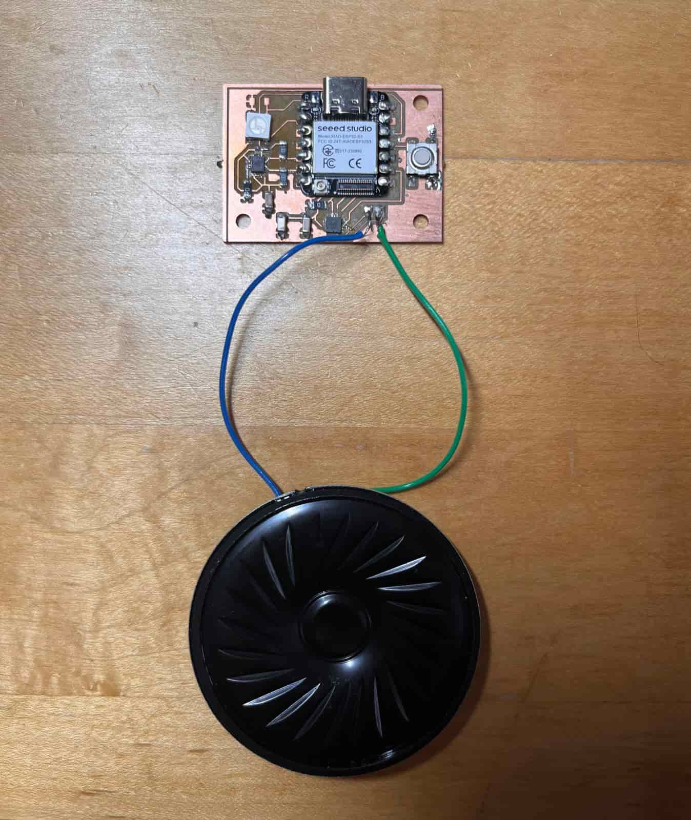
I'm still using the PCB I built from input and output weeks, with a ESP32S3 mcu, a RGB LED, IMU, speaker, and a button.
3D Printing a Case
To 3D print a case, I first designed a magic wand in Fusion 360 by drawing the contours and using the revolve feature to get a cylindrical shape for the wand. I also added a placeholder for my PCB.
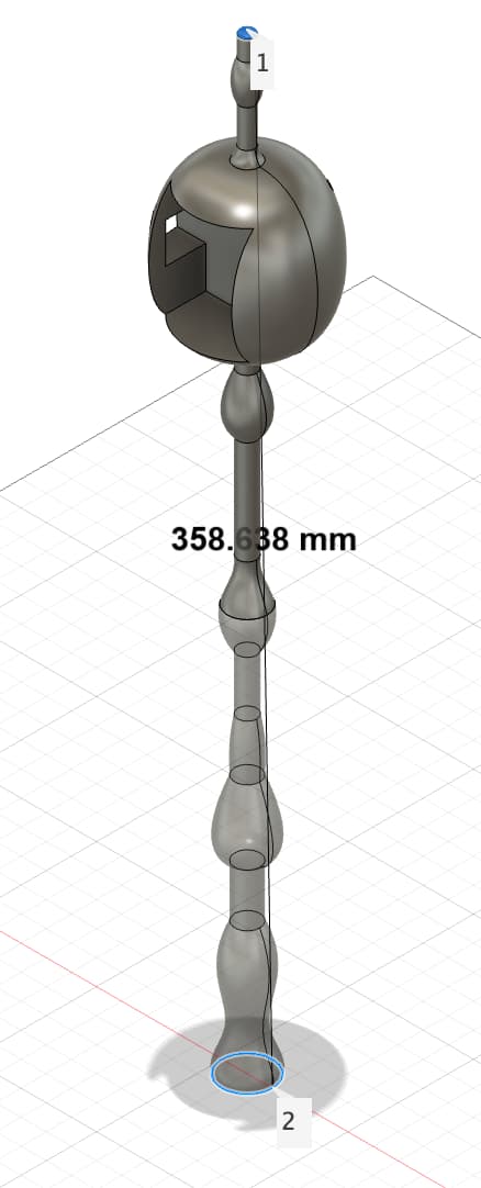
However, the wand's 36mm length is too big for the Prusa and Formlab printers, so I had to split the wand in half.
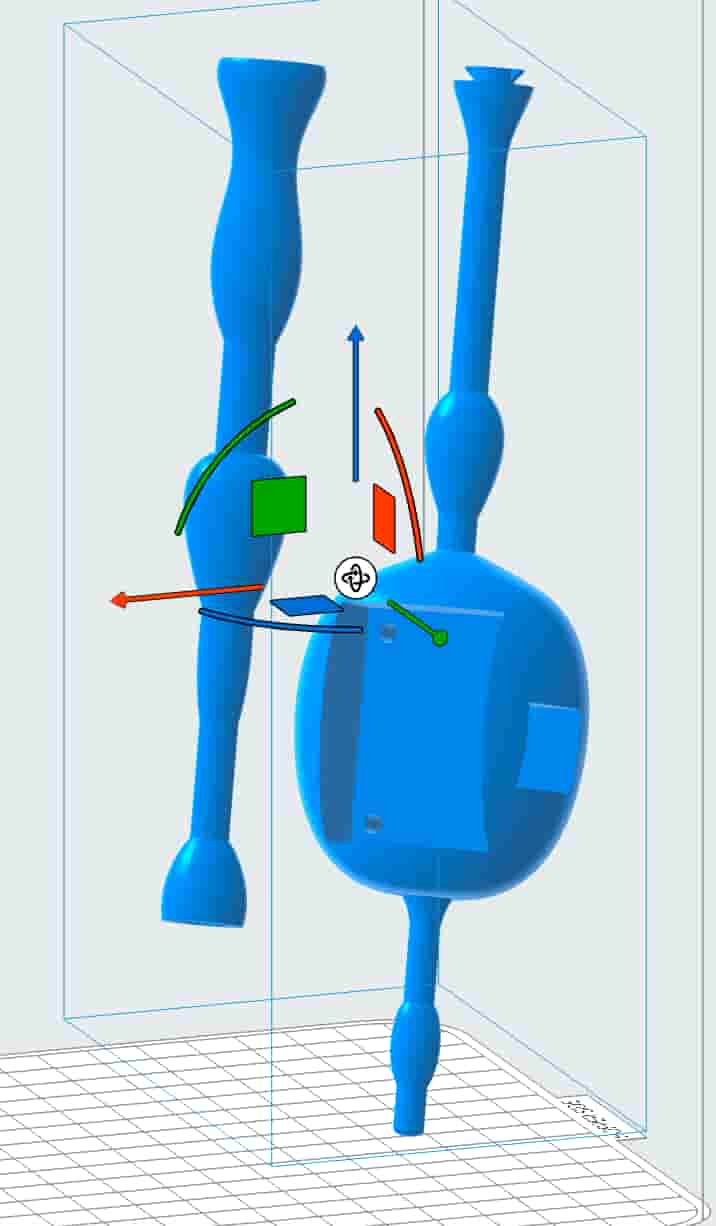
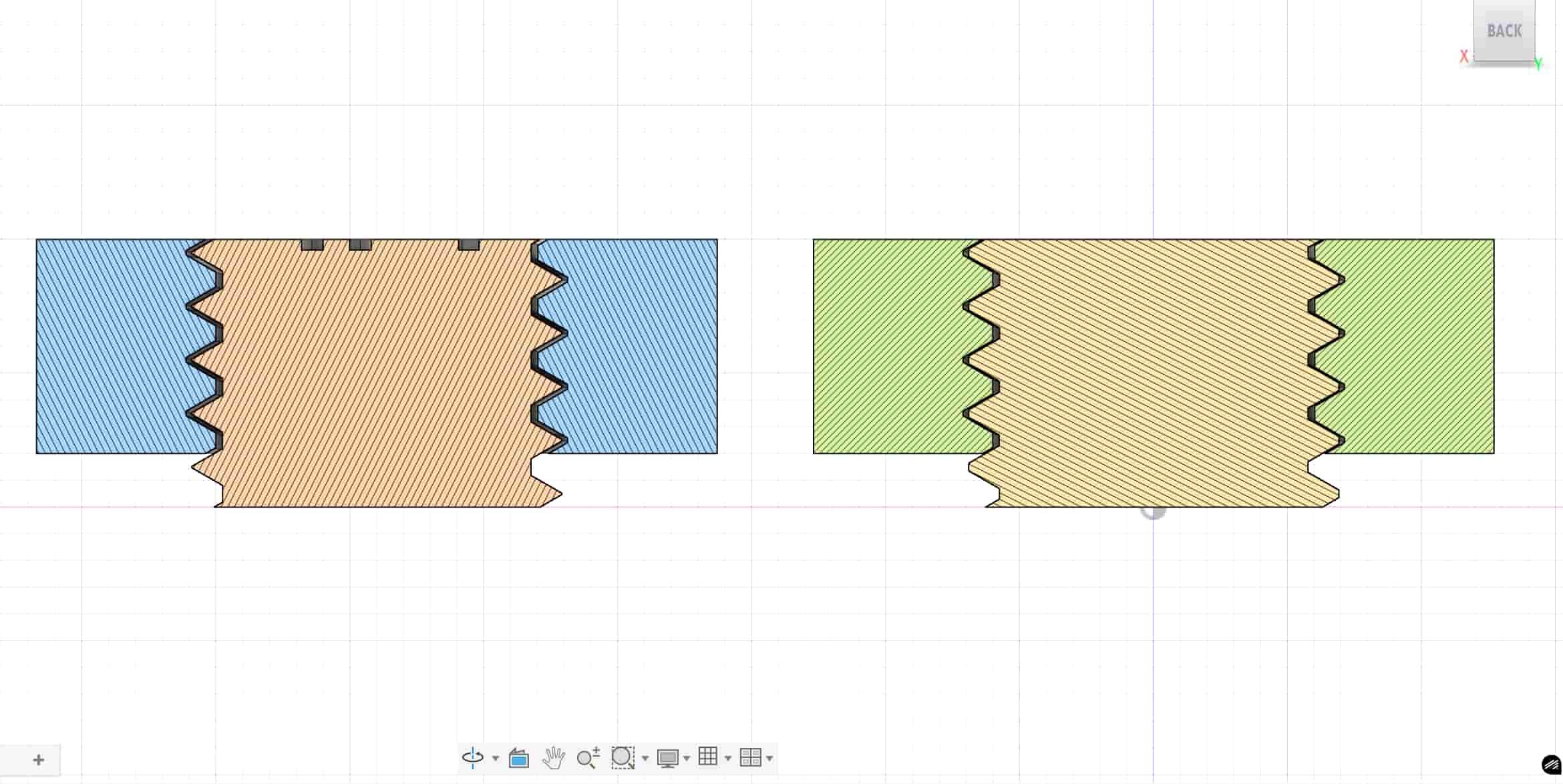
I used a snap-fit design to split the wand in half, so that I would press the top half of the wand onto the bottom half, and then slightly rotate it to fit. Here's the first print from the Prusa printers:
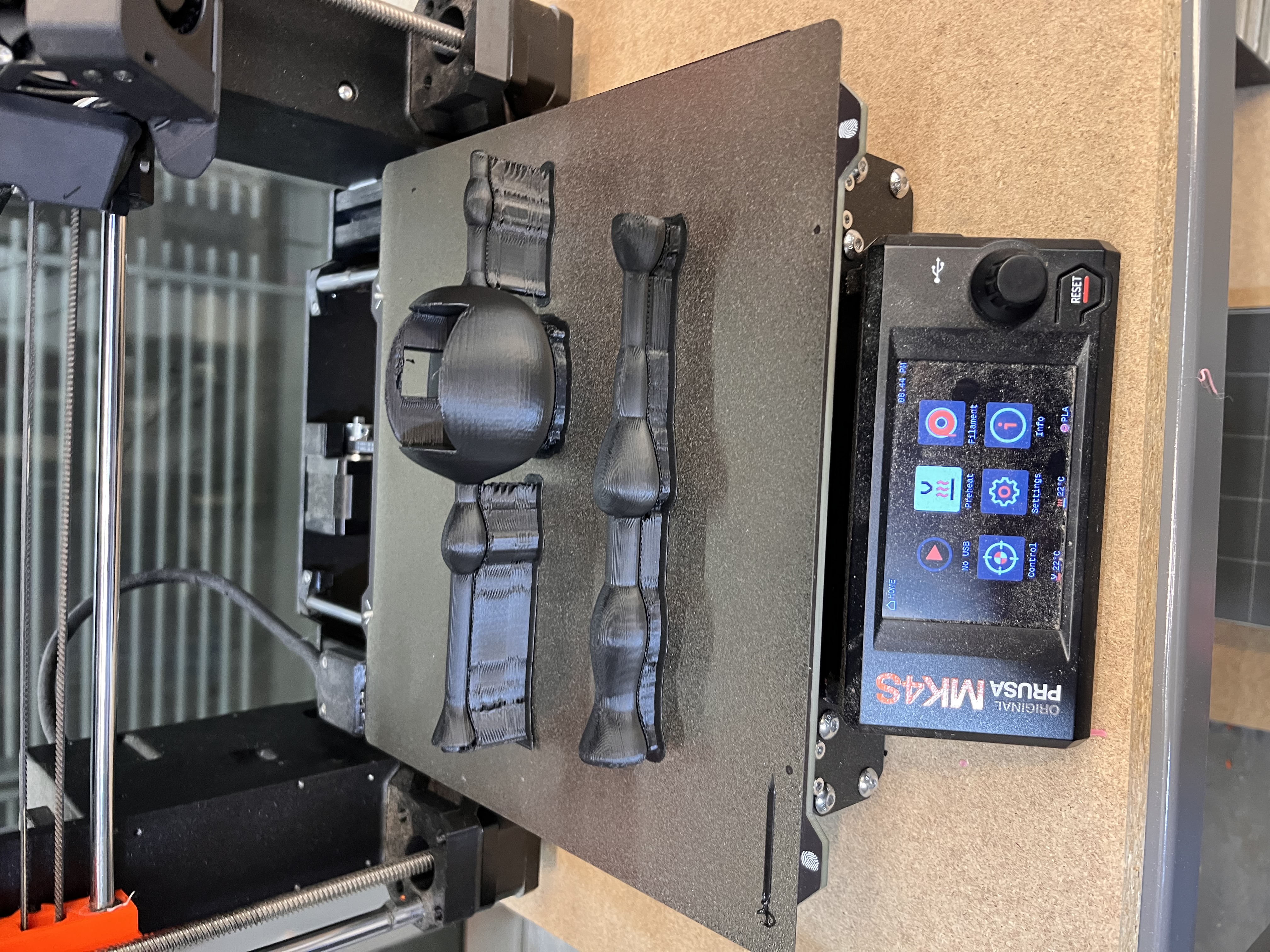
The print was not perfect, as some of the layering is very obvious. The snap fit design also didn't quite work out because the prusa printer wasn't able to get such fine details on a small object, and the support inside the fit was hard to remove. While the two pieces do come together, it doesn't really rotate into the cavity I left to lock them in.
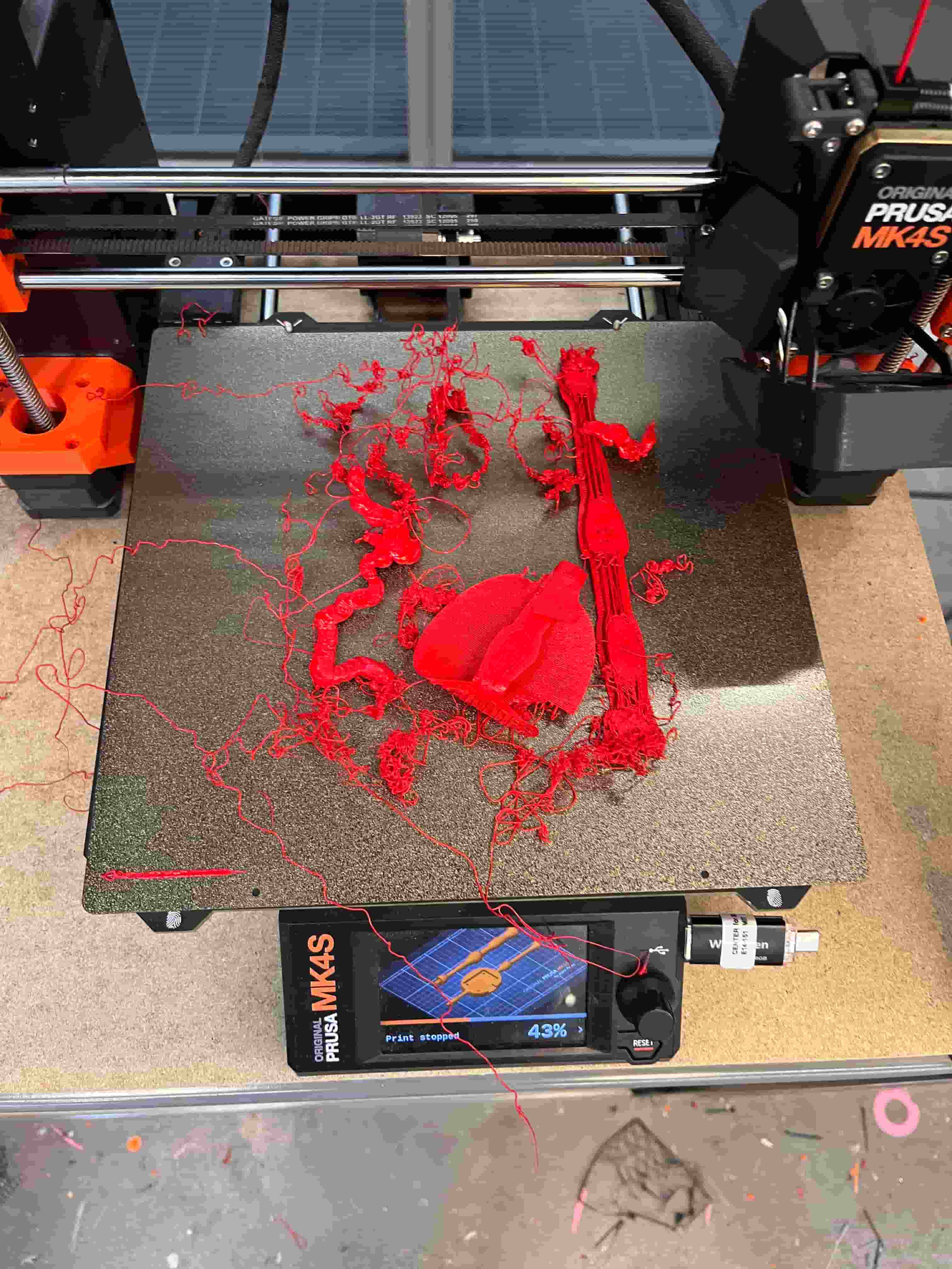
I wanted to give it another shot on with a 0.1mm speed. However, the pieces exploded during the print and I was unsure what went wrong.
With Sun's suggestion, I decided to implement a nut and bolt design, so I can screw in the top half and bottom half. I started learning the thread feature in Fusion 360, and added the thread to both parts of the wand.
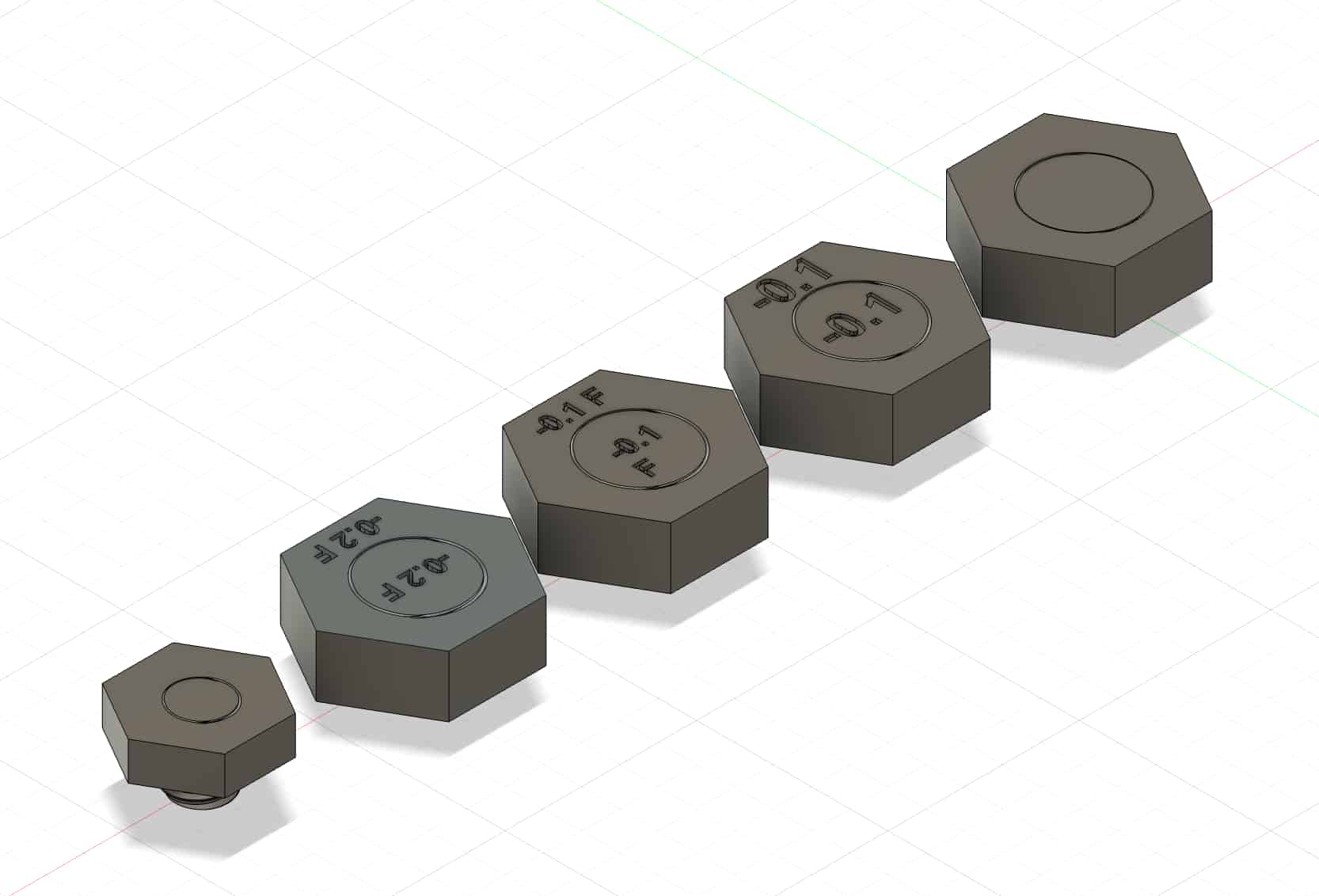
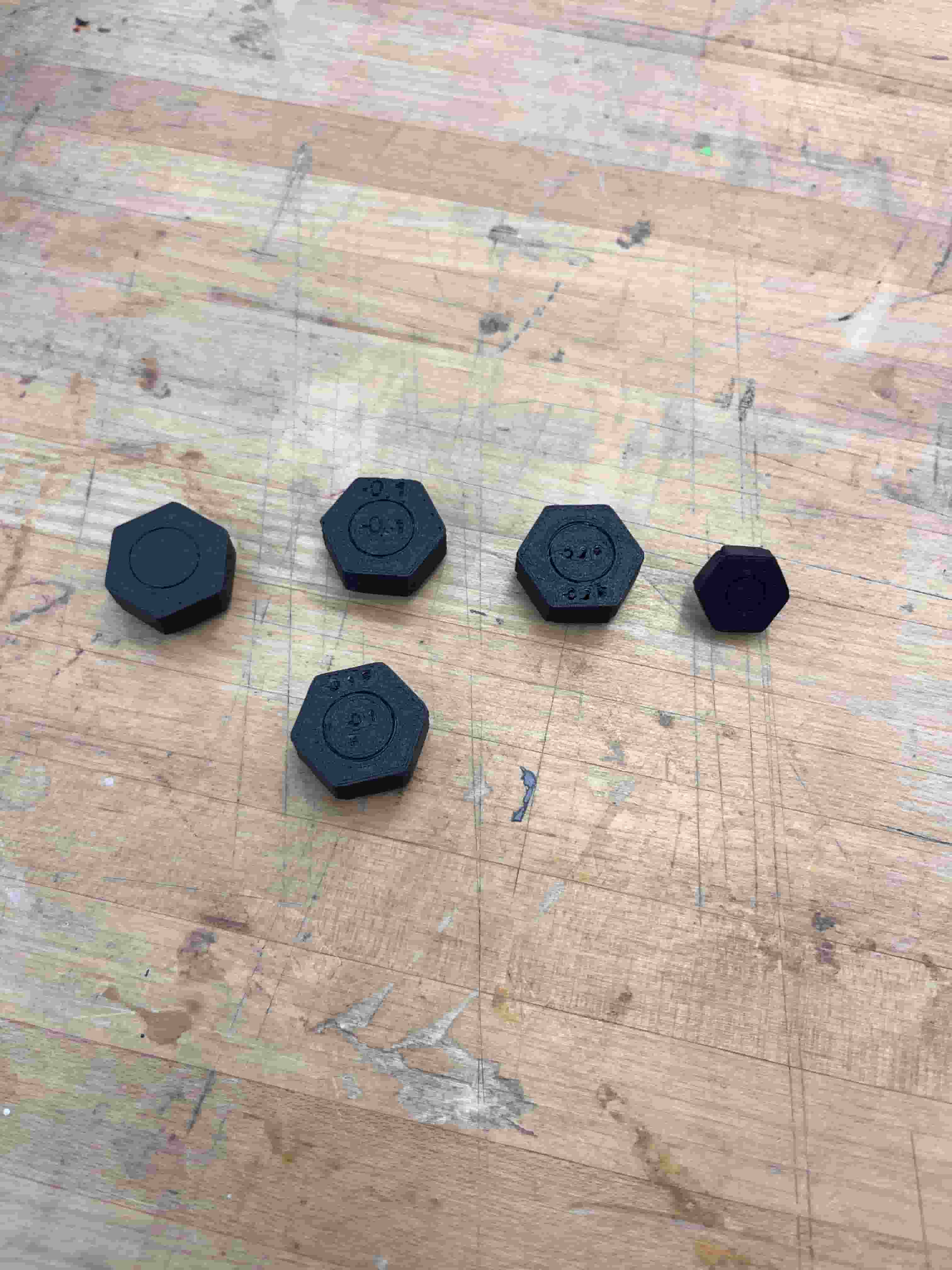
But first, I wanted to test different margins of design so I created a few different variations to test the specific design requirement for the 3D printers. I used the cross-section analysis in Fusion 360 to inspect the margin within the thread.
I tried to add different offsets such as 0.15mm or 0.2mm to find the sweet spot so enough space can be saved for the threading.
Then, I started a print on the Prusa printer, but the result wasn't very promising. The Prusa printers aren't able to get small pitched threads at high accuracy. I couldn't really rotate or move the nut and bolt so it was basically useless.
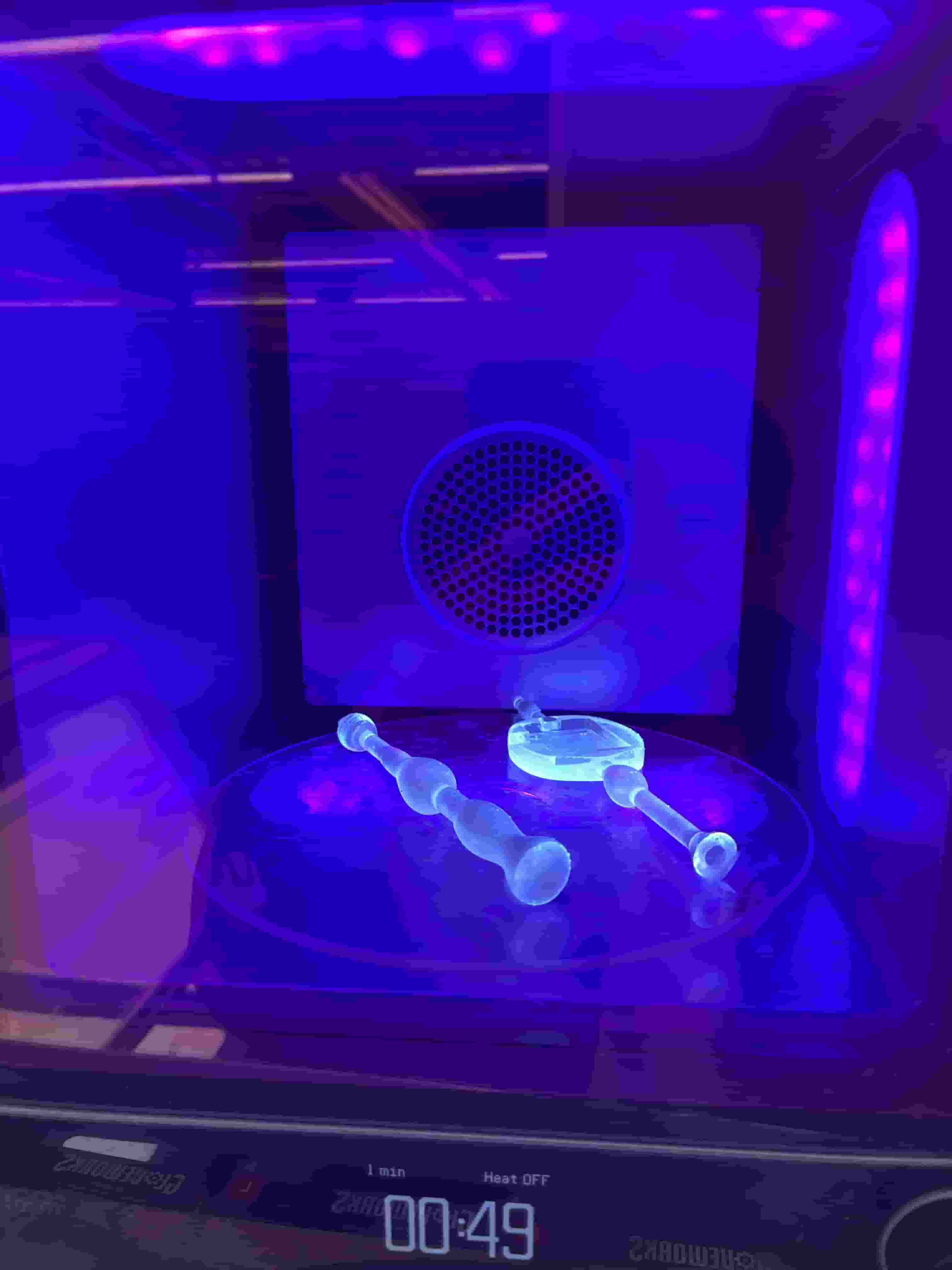
 I then switched to the Formlabs resin printer. I previously tried to use Prusa because I believe the snap-fit design would require some flexibility in the material. But now I could totally use the Formlabs printer. I set my layer height to 0.025mm to help improve the print result.
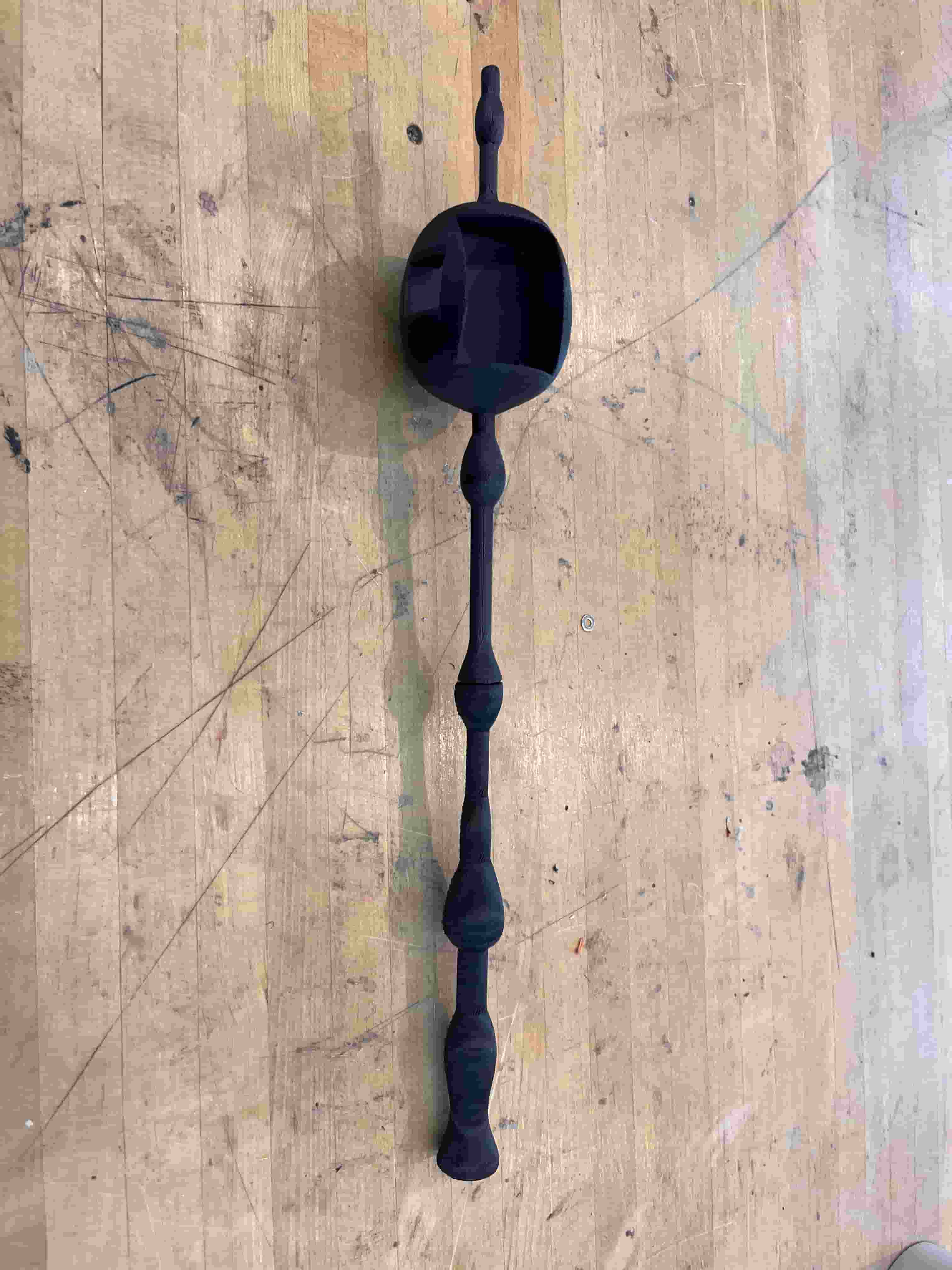
After 16 hours of wait, I finally got a very nice looking wand design.
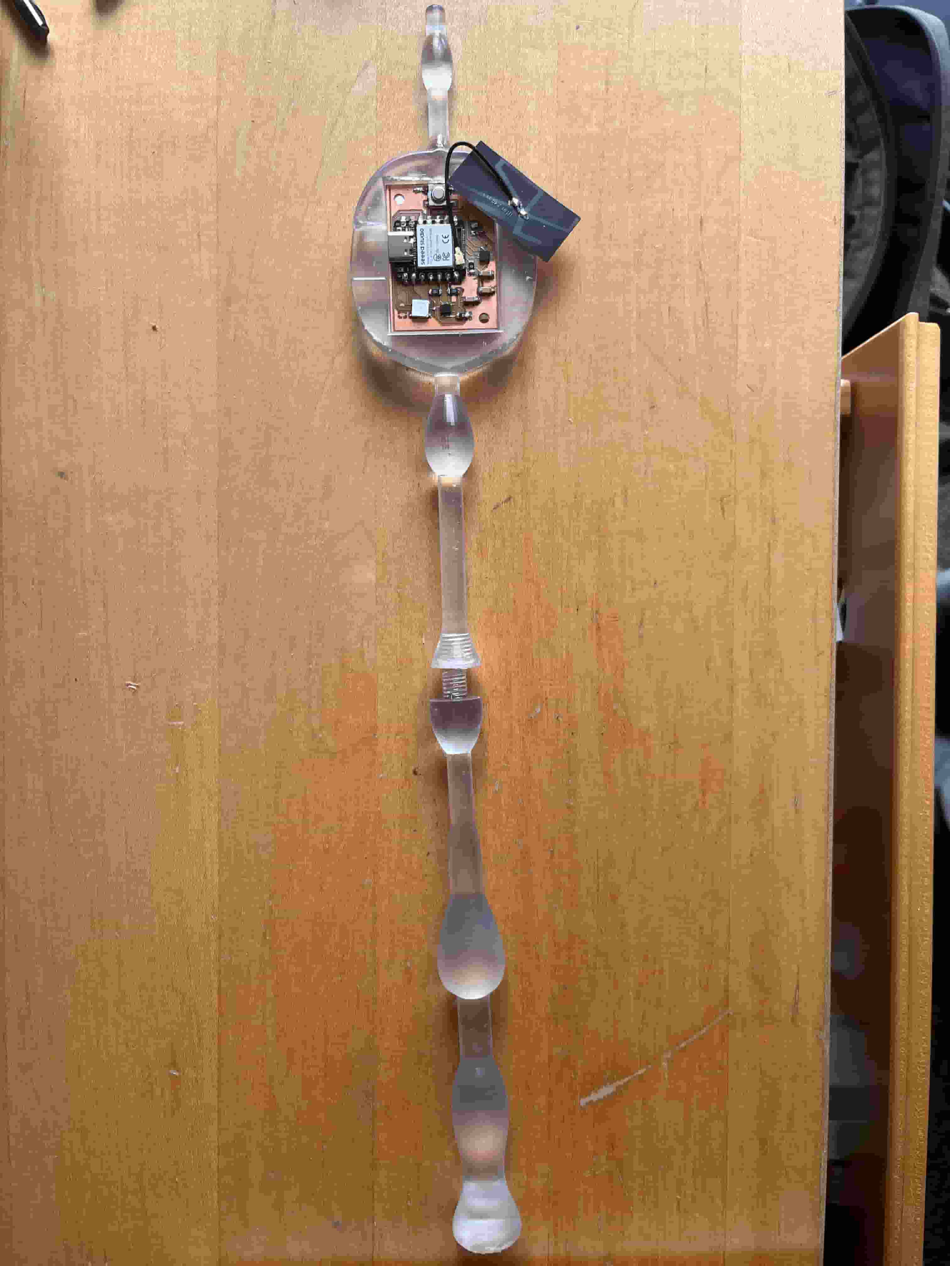
Here's the two pieces screwed in together. While it doesn't fully screw in, it's able to do so about half way to connect the two pieces of the wand together, so I will be satisfied for now.

Networking
There's two part to the networking and communications design. I need the embedded code to send the data through WIFI and my python server to listen to the data and show it on a canvas. First, I placed my PCB inside the wand and attached the antenna, which will help my PCB connect to the WIFI network.
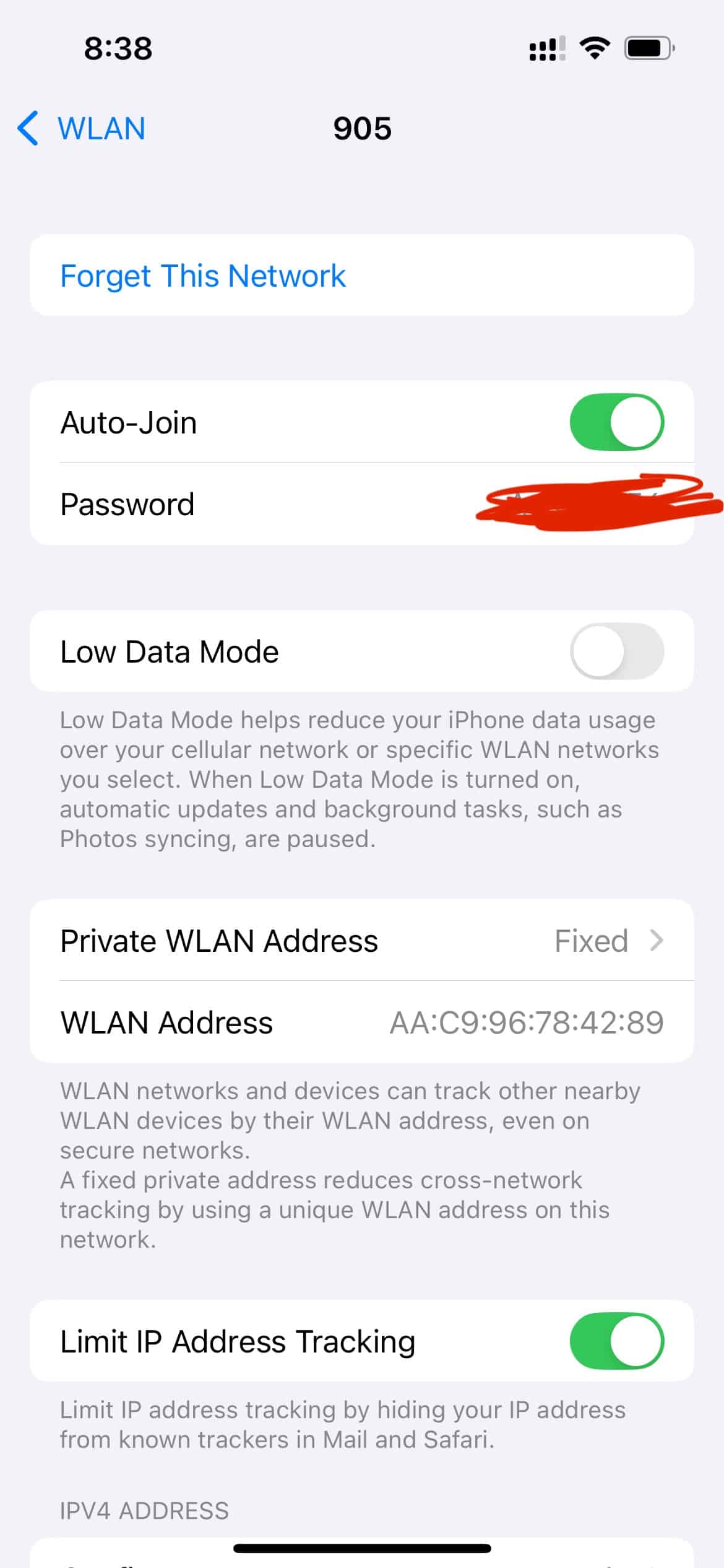
Then, I need to find the credentials for the wifi, which can be found by clicking into iPhone's wifi connection.
ESP32 WiFi Connection Code
                #include <WiFi.h>

                const char* ssid = "MIT";
                const char* password = "YOUR_WIFI_PASSWORD";

                void setup() {
                    Serial.begin(115200);

                    WiFi.mode(WIFI_STA);
                    WiFi.setAutoReconnect(true);
                    WiFi.persistent(true);
                    WiFi.begin(ssid, password);

                    while (WiFi.status() != WL_CONNECTED) {
                        delay(200);
                        Serial.print(".");
                    }

                    Serial.println("WiFi connected");
                    Serial.println(WiFi.localIP());
                }

                void loop() {
                    if (WiFi.status() != WL_CONNECTED) {
                        WiFi.reconnect();
                    }
                }
Server
After setting up the Arduino code, I also need a Python server to receive the data and show the data on a canvas, which helps visualize the IMU data collected.
The server is built by opening a UDP socket and binding it to a fixed host and port to continuously listen for incoming packets from the ESP32-S3.
        sock = socket.socket(socket.AF_INET, socket.SOCK_DGRAM)
        sock.bind((LISTEN_HOST, LISTEN_PORT))
        sock.settimeout(0.5)
Each packet is then parsed based on its packet type, such as QUAT, ACCEL, GYRO, or GRAV.
        data, addr = sock.recvfrom(1024)
        decoded = data.decode("utf-8").strip()
        parts = decoded.split(",")

        packet_type = parts[0]
The packet is then structured into IMUData objects, which contains all IMU sensor data as follows:
        @dataclass
        class IMUData:
            quaternion: Optional[Quaternion] = None
            accelerometer: Optional[Tuple[int, int, int]] = None
            gyroscope: Optional[Tuple[int, int, int]] = None
            gravity: Optional[Tuple[int, int, int]] = None
            timestamp: float = 0.0
These objects are then pushed into a queue for Tkinter to interpret.
        imu_data = IMUData()
        imu_data.quaternion = Quaternion(qw, qx, qy, qz).normalized()
        imu_data.timestamp = time.time()

        data_queue.put(imu_data)
Tkinter works by popping the queue to update its canvas frame in its loop, redrawing the wand's tip position and path.
        while True:
            new_data = self.data_queue.get_nowait()
            self.current_data.quaternion = new_data.quaternion
A Kalman filter was added to smoothen out the IMU’s quaternion and reduce jitter in the visualized path.
        # Quaternion smoothing (SLERP)
        self.smoothed_quat = slerp(
            self.smoothed_quat,
            new_data.quaternion,
            self.slerp_alpha
        )

        # Path smoothing (Kalman filter)
        filtered_2d = self.kalman.update(raw_2d, dt)
Debugging
After setting up the arduino code, I also need a python server to receive the data and show the data on a canvas, which will help me visualize the IMU data collected.
I realized that I need to find the ip address of my mac computer. I opened the terminal and used the ipconfig command to find the address of my mac. Then, I input the address in the embedded code so that my PCB knows where to send the data to through WIFI.
After checking through the code multiple times to see no data is sending over and the serial monitor is stuck in connecting to WIFI, I finally realized that I forgot to insert the WIFI antenna to my XIAO ESP32S3 mcu. How stupid of me!
IMU In TKinter
I finally got it to work! While it doesn't reflect the path accurately, it does show an interface responding to the incoming IMU data packets.
Resources and Acknowledgements
Tools used:
- Formlabs
- Prusa MK4S
- Fusion 360
- Arduino IDE
- ChatGPT
- Cursor