Week 7
Computer Controlled Machining
10/15/2025-10/22/2025
Group Assignment
Here's the link to our group assignment: group assignment
For the group assignment, I checked the margin/kerf for the CNC machine with Ceci and Sophia. We found that a kerf of 0.1mm is good for the stock we were using.
Ideas
I want to build a chair/sofa for my dorm room. Currently, I can only sit in my chair or my bed to do work, but it would be nice if I have a nice cozy sofa to relax and do some work in. Getting a good quality sofa is expensive, and especially some of the nicer ones with more features. For example, a zero gravity chair that allows reclining stands at around $2,000.
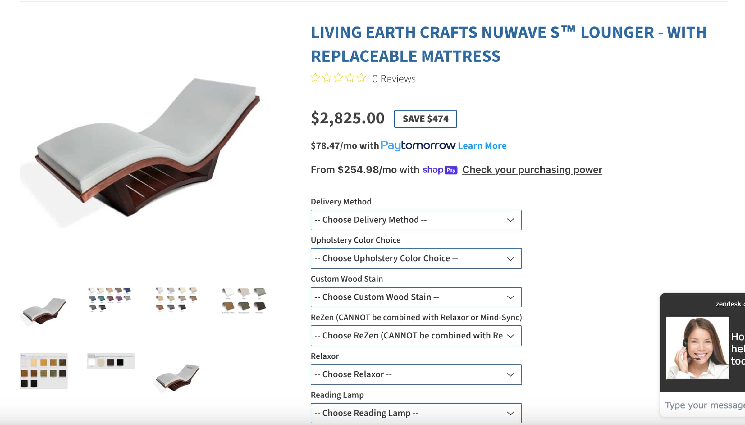
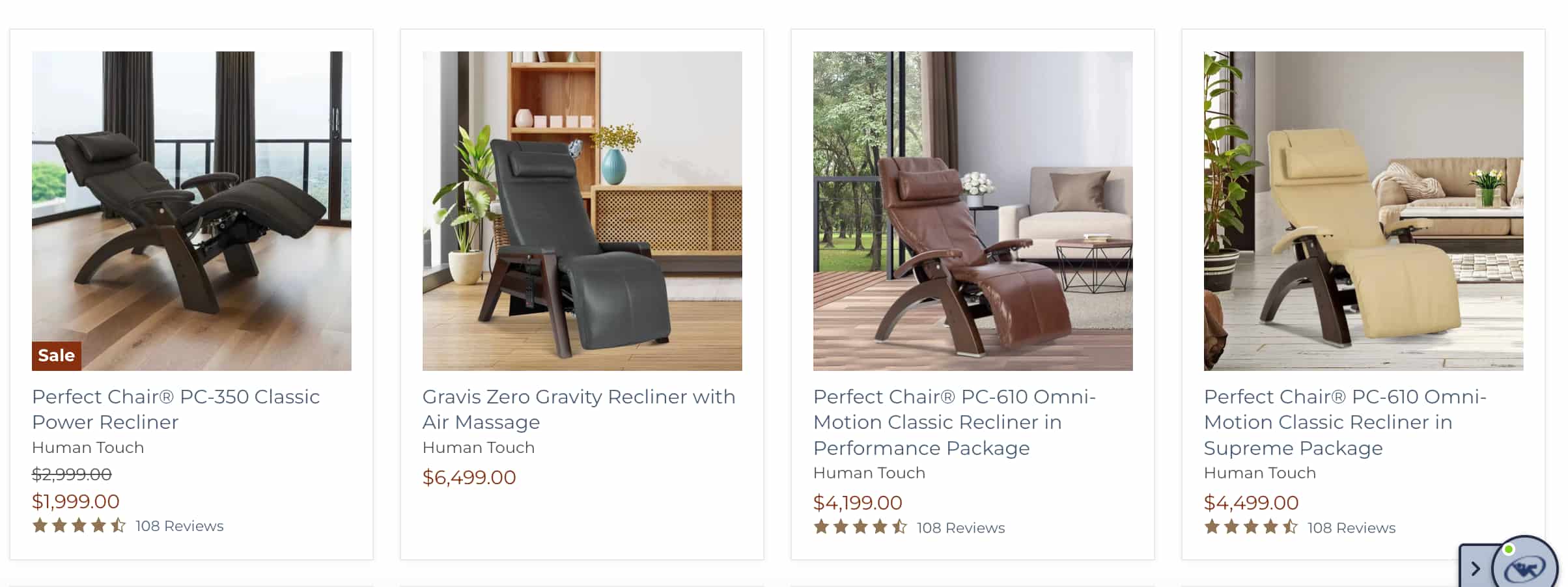
It is very enticing to build something for myself so I have a personal space to sit and relax in.
I also created some sketches to get a better feel of how the sofa will be laid out.
Ideas
I want to build a chair/sofa for my dorm room. Currently, I can only sit in my chair or my bed to do work, but it would be nice if I have a nice cozy sofa to relax and do some work in. Getting a good quality sofa is expensive, and especially some of the nicer ones with more features. For example, a zero gravity chair that allows reclining stands at around $2,000.
It is very enticing to build something for myself so I have a personal space to sit and relax in.
I also created some sketches to get a better feel of how the sofa will be laid out.
3D Model
I started 3D modeling by visualizing what my bench would look like and developing all my parts on one plane. This is a little challenging and unorganized as I constantly needed to check where each part goes and which part is still missing.
I also realized that my first design would not fit on the 4ft by 8ft stock provided. I definitely was a little ambitious in wanting to build a full sofa with good support for my seating position. Realizing that all of my parts together won't fit in the stock, I needed a smaller design
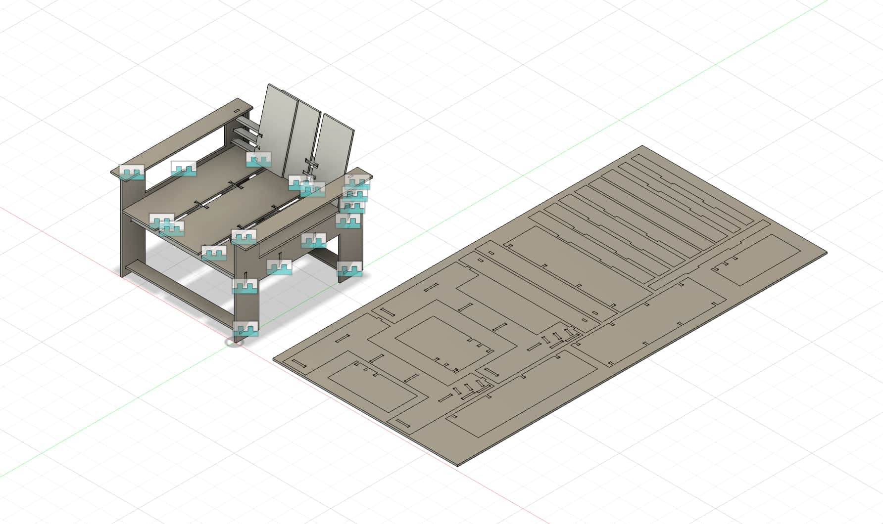
Later, I learned from Ceci that it is better to assemble all my parts before arranging them on the stock. Since I didn't model anything too complex in the earlier weeks, I need to learn how to use joint in Fusion 360 to assemble all of my parts. I also modified my design to use less parts. For example, I reduced the height of the back holster so the back support mostly holds the lower back of the body, compared to before where I had my back support trying to go higher to support my upper back and head. In addition, I reduced some materials from the side frame, changing it from a full enclosed design to a H-shaped design to open up more space for me to place connecting parts during the cut in these extra spaces. My new design takes inspiration from a previous project built by Alice Nasto.
This time, I designed all my parts and assembled them using the Fusion joint feature. I then used arrange feature to easily lay all of my components on a rectangular solid with the same dimension of the stock, which is 96 inches by 48 inches.
I also realized that I forgot to add dogbone to my inner cuts. I used the add-ins to do it but it doesn't work for all of my components. So I had to manually add the circles with radius of 0.25 inches. Ceci also told me to add straight lines tangent to the circle so it allows the endmill to enter and create the dogbone.
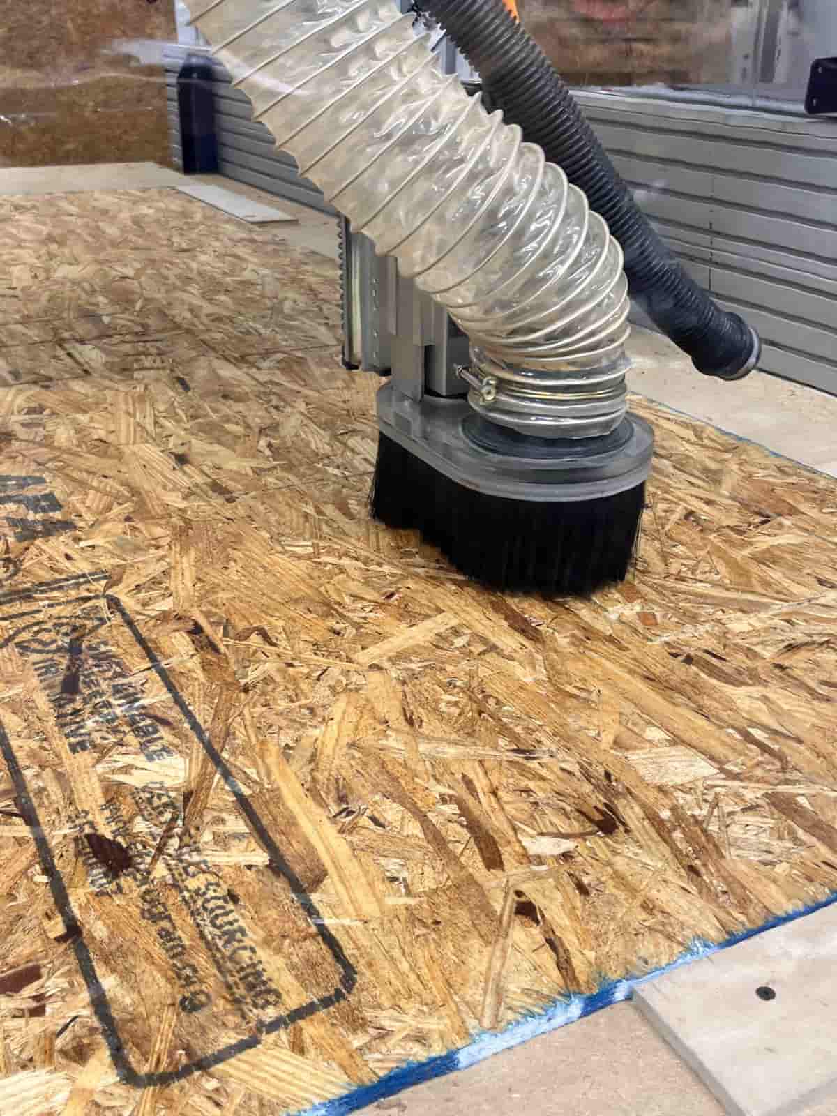
CNC Machining
When I started my first cut, I quickly realized that the milling machine is going in the wrong direction. It was actually moving outside of the cut area. I went back to check my manufacturing setup in Fusion and discovered that my x & y axis were pointing in the opposite direction of the stock. After consulting Ceci, I learned that my axis need to be pointing in the direction of my stock so that the machine will go in the correct direction.
In my second go, I made sure that axis are set properly.
However, the program popped a question that if I'm using tool spindle 2. Something felt wrong, but I couldn't distinguish between upcut or downcut endmills. I referenced the manual to find that the person before me used
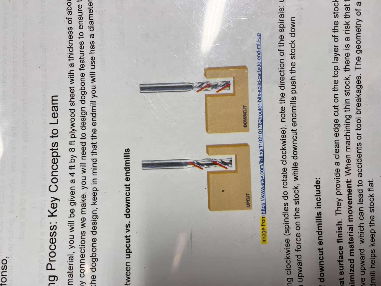
I noticed that the endmill is downcut whereas I wanted to use upcut. I referenced the manual to replace the downcut endmill with an upcut endmill. I used two different cut settings to cut, so it would take the machine two pass to complete the cutting. Here's the setting I used for my first pass:
- Spindle Speed: 10000rpm
- Cutting Feedrate: 150 in/min
- Tabs: True
- Tab Width: 0.25 in
- Tab Height: 0.30 in
- Tab Distance: 3 in
- Top Height: 0 in from Stock Top
- Bottom Height: -0.2 in from Stock Top
Here's the setting I used for my second contour pass:
- Spindle Speed: 10000rpm
- Cutting Feedrate: 200 in/min
- Tabs: True
- Tab Width: 0.25 in
- Tab Height: 0.30 in
- Tab Distance: 3 in
- Top Height: 0 in from Stock Top
- Bottom Height: -0.05 in from Stock Top
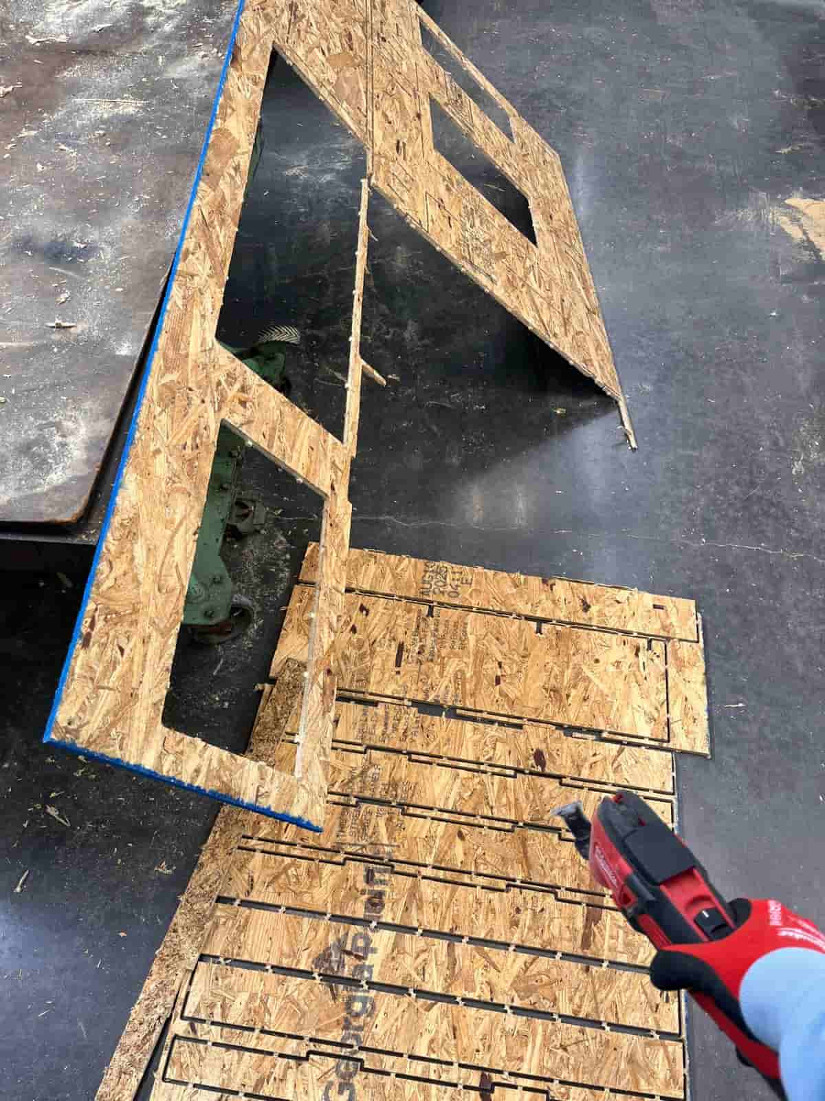
The cut finally works!
Assembly
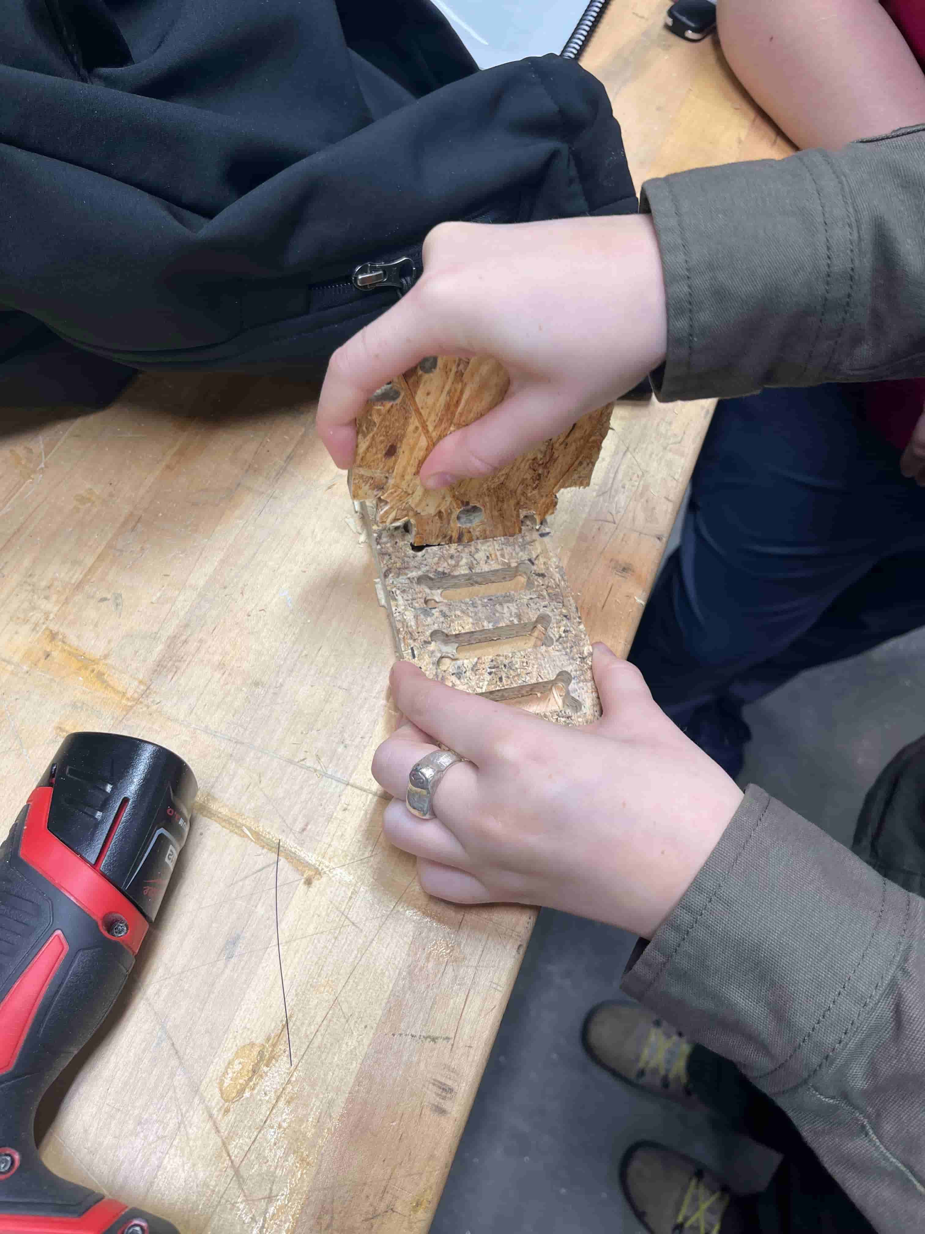
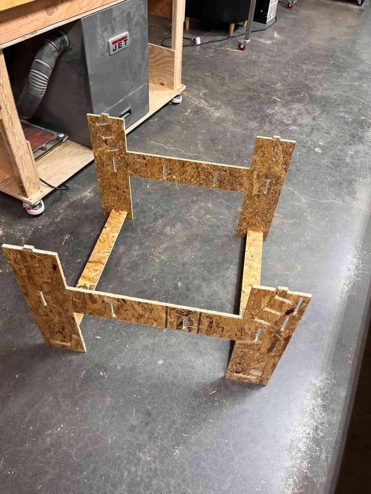
Now it's time for assembly. I first removed all the tabs and smoothened the edges of each piece.
Then, I started putting all of the pieces together based on my design.
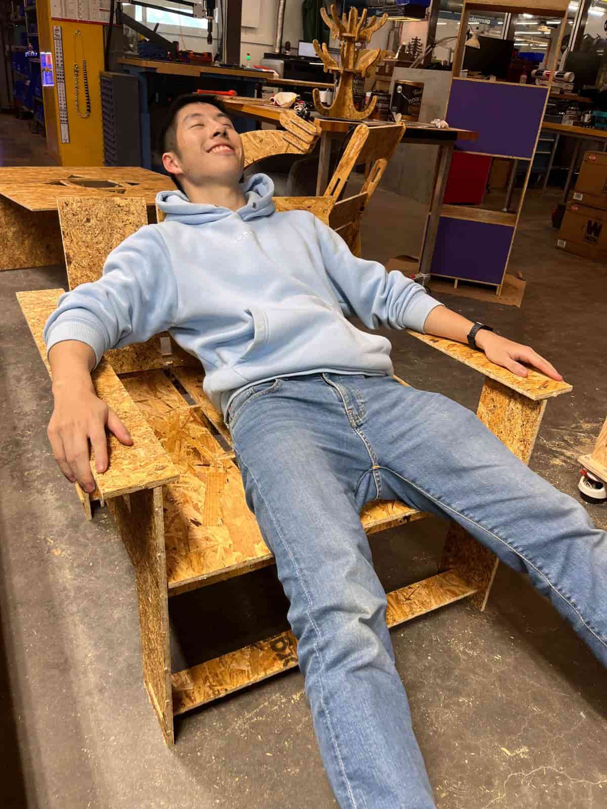
Here is the complete look of my chair!
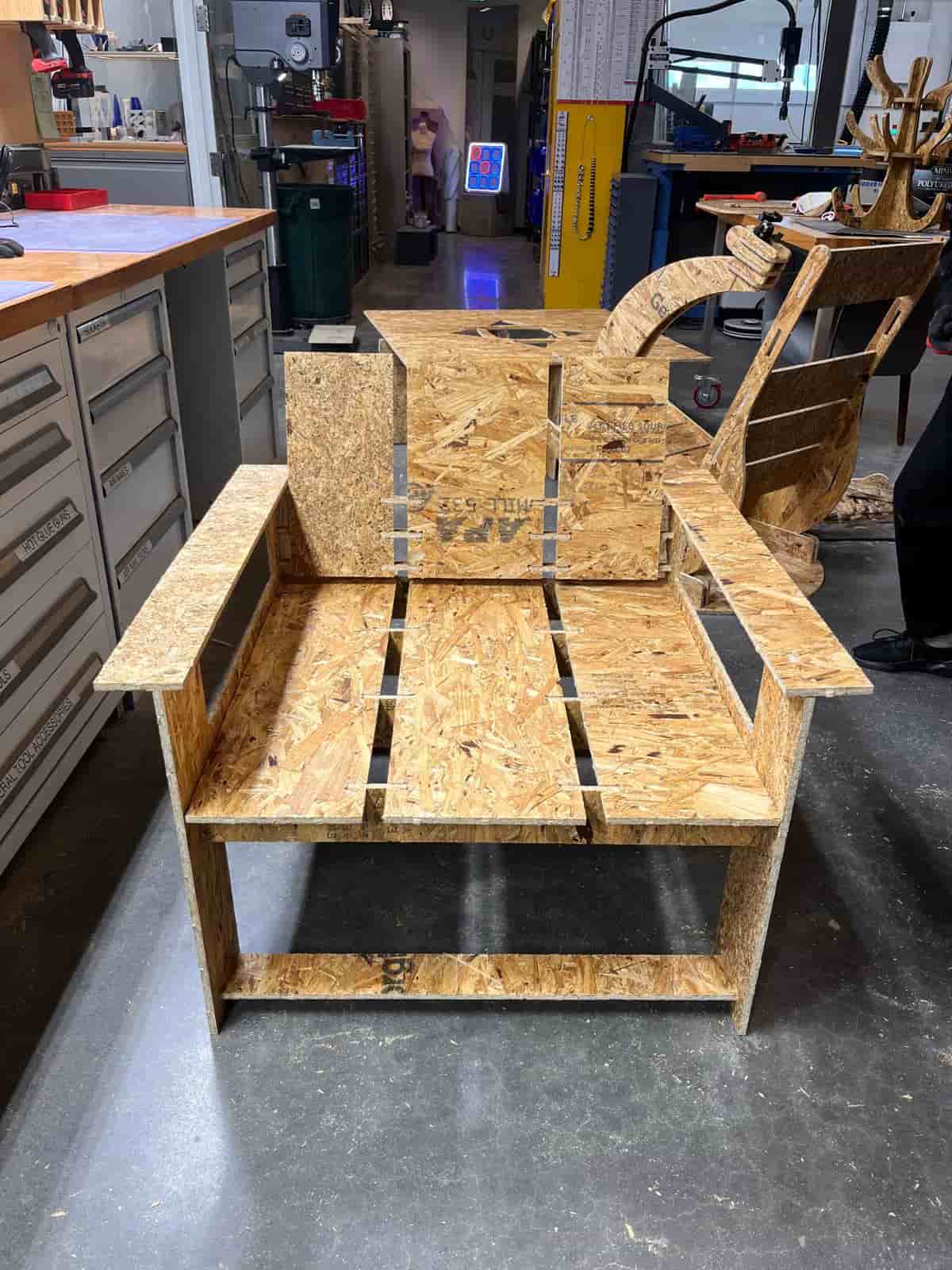
I was a little worried about trying my chair because I didn't know whether the structural integrity can support my weight. Fortunately, it passed the human test.
Next step is to add the special paint to protect myself from the wood splinters. I also plan to add some paddings and some leather surface to turn the chair into a sofa that I can place in my dorm room.
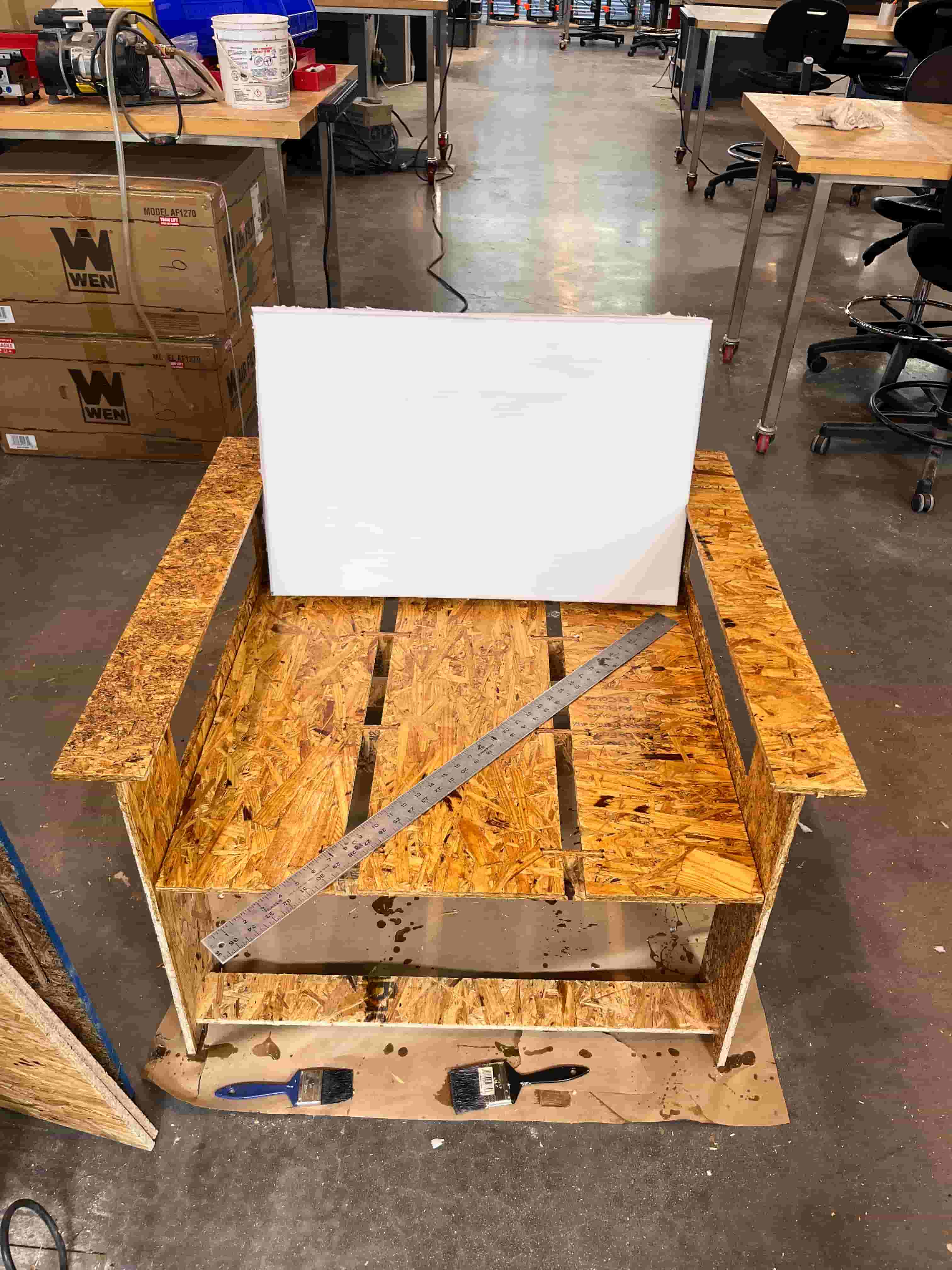
Post Processing
I really want this chair to be used in my daily life as a spot for me to relax and do some work before sleeping. I would call this the the the one hour stretcher, so it would balance the last hour before my sleep, where I would still like to do some work, but I also want to lean back and sit comfortably to relax and unwind.
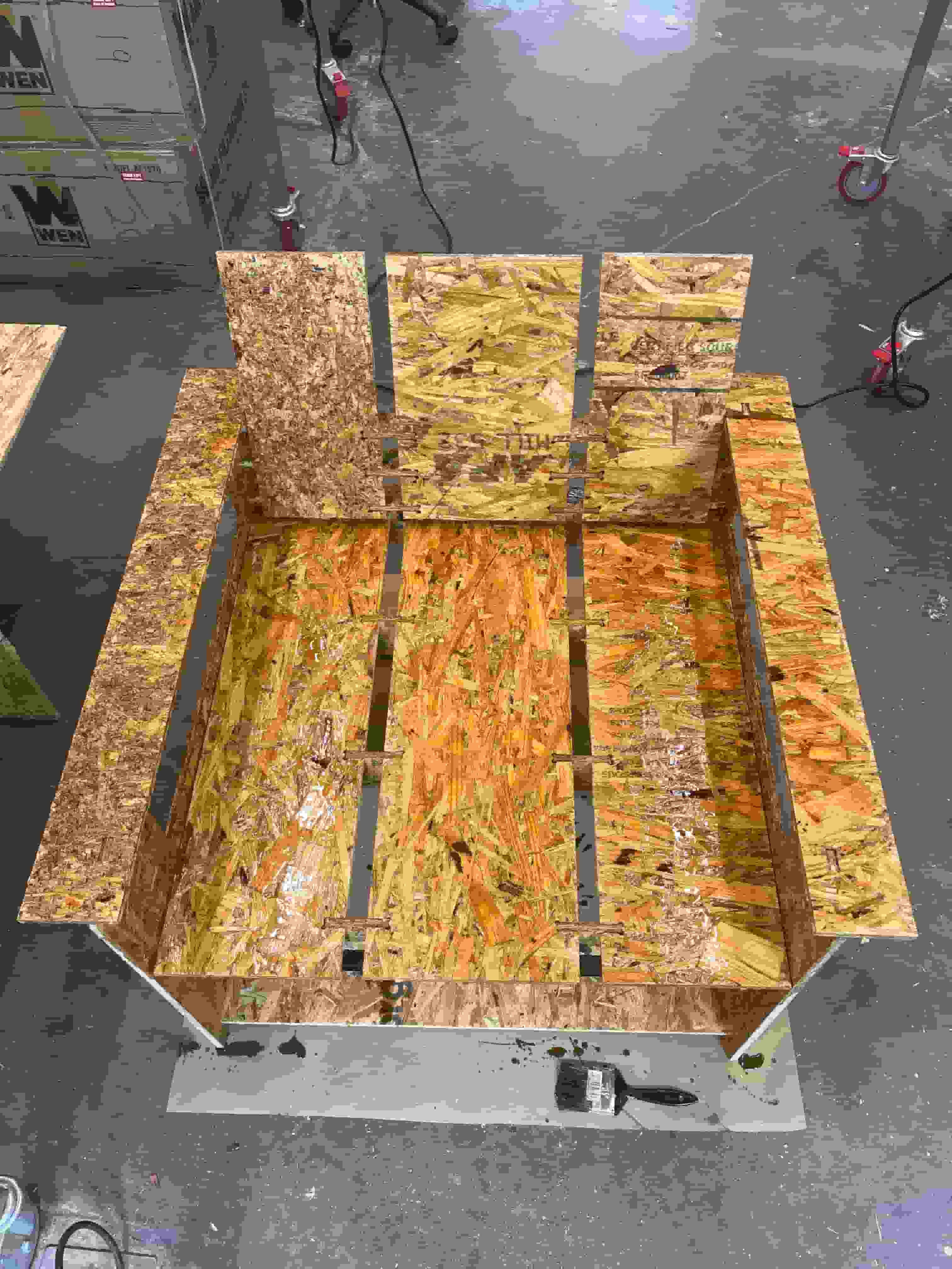
First, I need to add wood sealer paint to it to prevent the wood from sticking and poking out.
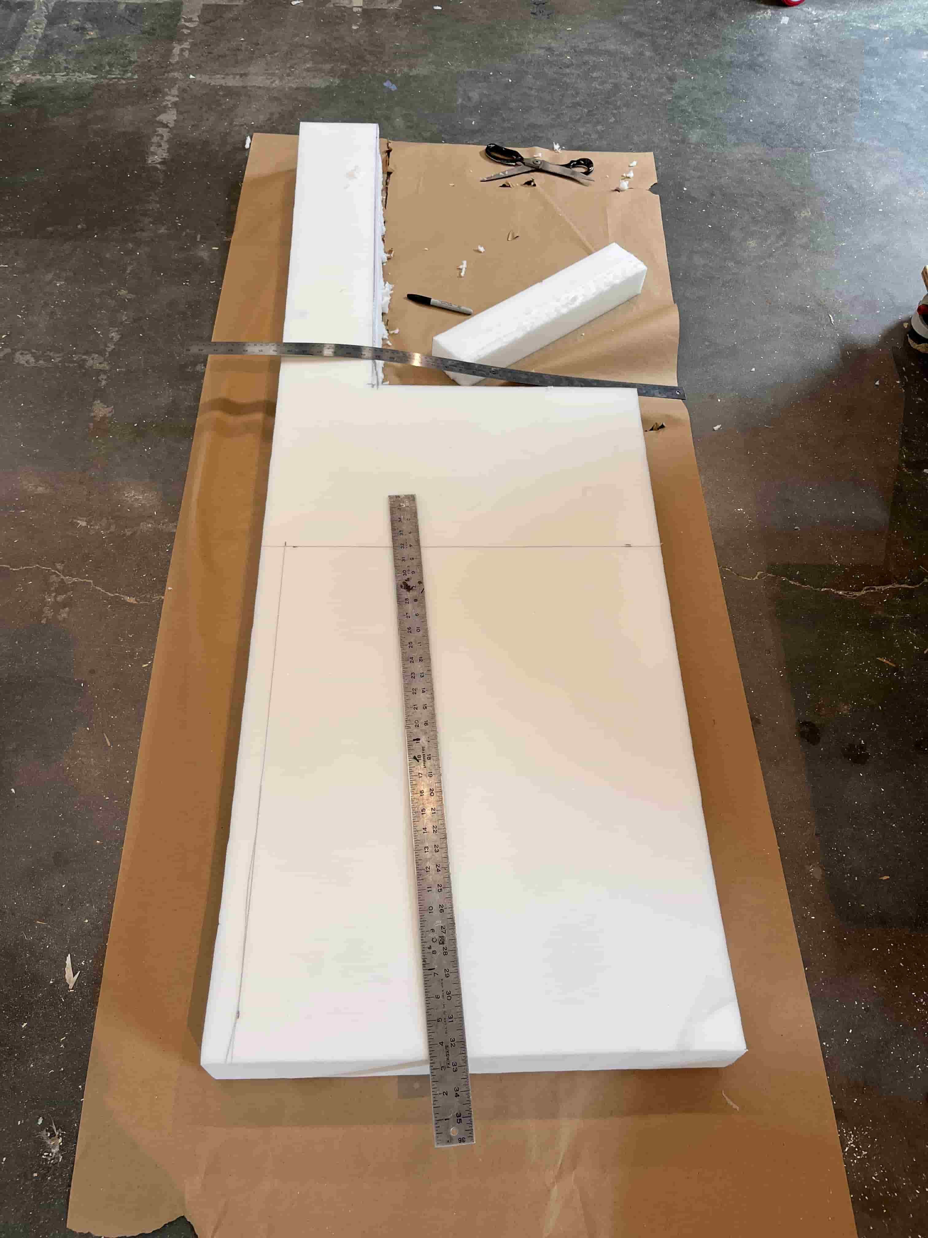
I first purchased some foam and cover to make the seating more comfortable. When the foam arrived, I brought it into the shop to cut it. Initially, I was struggling to find the right tools to cut the foam, because the vertical blade makes the cutting edge very wretched. I eventually switched to a large scissor, and using one end of the scissor to act as a knife and just pull it all the way through the cut. The cutting is pretty smooth, but since the foam is taller than the scissor's blade, the cut at the very bottom is a little bit ragged.
After placing the foam on top, the next thing is to find glue to attach the foam on.
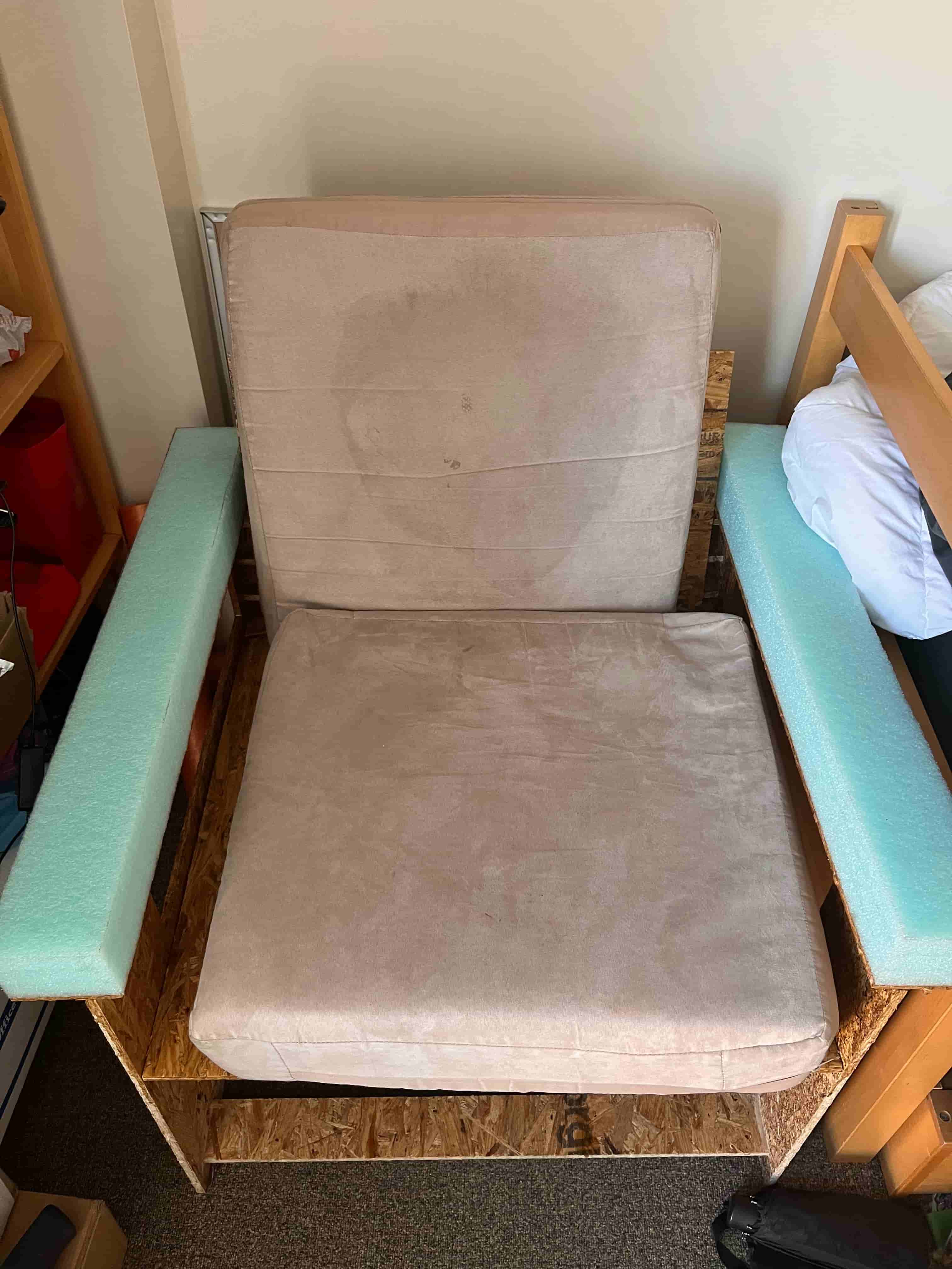
Then things got a little bit busy for me and I haven't returned in a few days. Due to many people's project being left in the shop and causing a burden, these projects alongside mine were removed. And my foam was taken by someone else. Fortunately, Dan provided me some cushions he found, and I just need to place them on my chair!
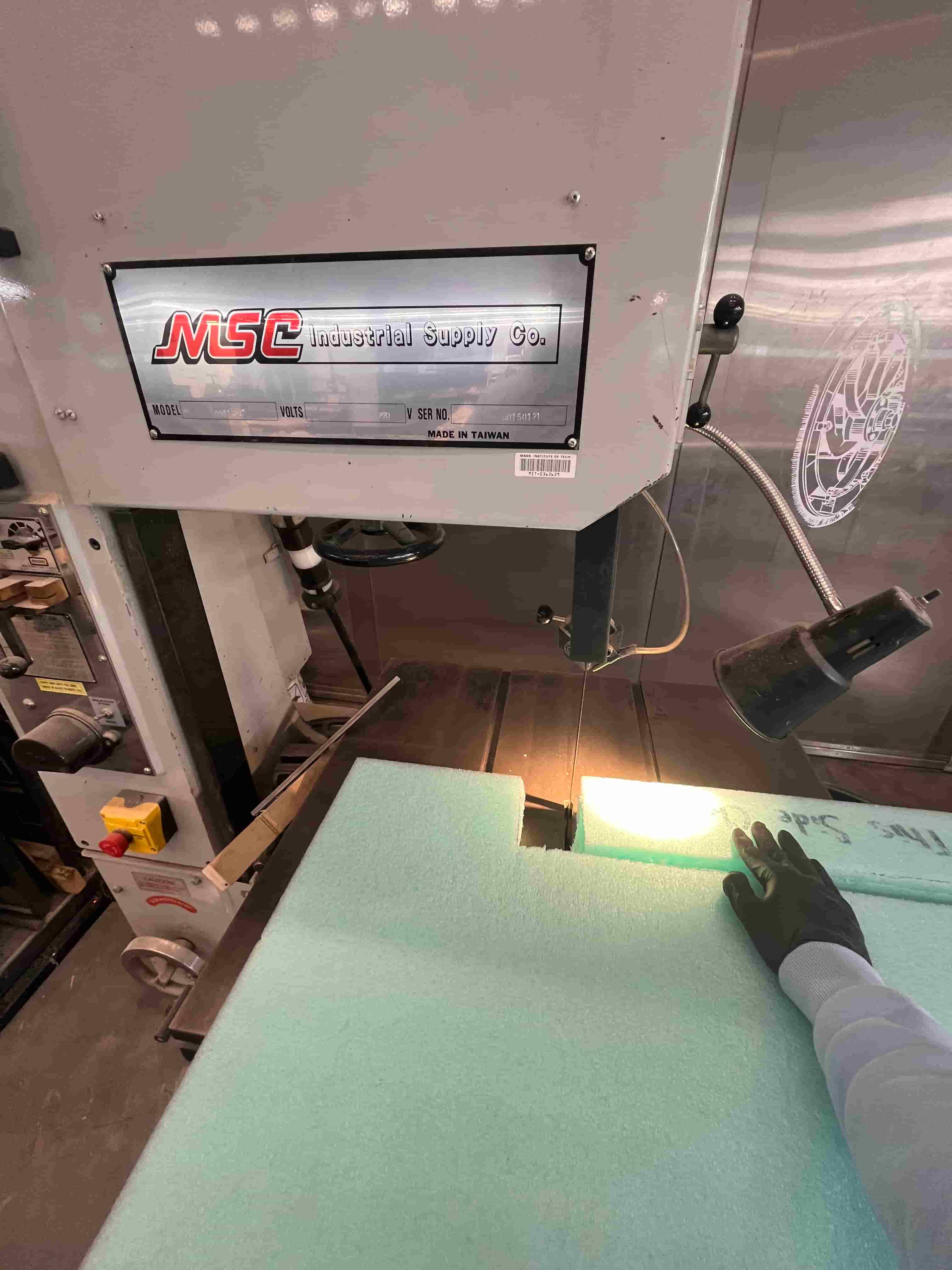
Dan showed me how to use the vertical band saw to cut the foam, which is much more efficient than my previous method of using the scissor. I cut out small rectangular shaped foams to raise the height of the hand rest, and to make it a little bit softer for my arms.
After putting everything together, now it's time to move the chair home. I must look crazy even at night pulling a massive chair across campus.
I do have to leave the windows in my room open for a few days to diffuse some of the paint and wood smells. I also had to wash the cushion covers to sanitize it. But now I have a chair in my room where I can relax in.
Resources and Acknowledgements
Tools used:
- ShopBot CNC
- Fusion 360
Thanks to Dan and Ceci for helping me immensely on this week's work.
Design Files
You can download the Fusion 360 files here