Week 8
Input Devices
10/15/2025-10/22/2025
Group Assignment
Here's the link to our group assignment: group assignment
For the group assignment, we learned how to use oscilloscopes to probe the analog and digital signals of the input device.
Ideas
I want to use the accelerometer to detect motion, the camera on ESP32-S3 to do facial recognition, the RGB LED for lighting, and the amplifier and speaker for audio outputs. Combining all these components together, I would combine this week and next week to make one device that contains both input and output devices. This would be a magic wand device that I train the motion sensor to learn the movements of the spells in Harry Potter, so that it would recognize the spell movements and then output the spell name through the amplifier. The LED will also shine based on the spell used. The facial recognition is used so that similar to the elder wand in Harry Potter, it recognizes its master and protected Harry when Voldemort casted the death spell in the finale.

Electronics Design
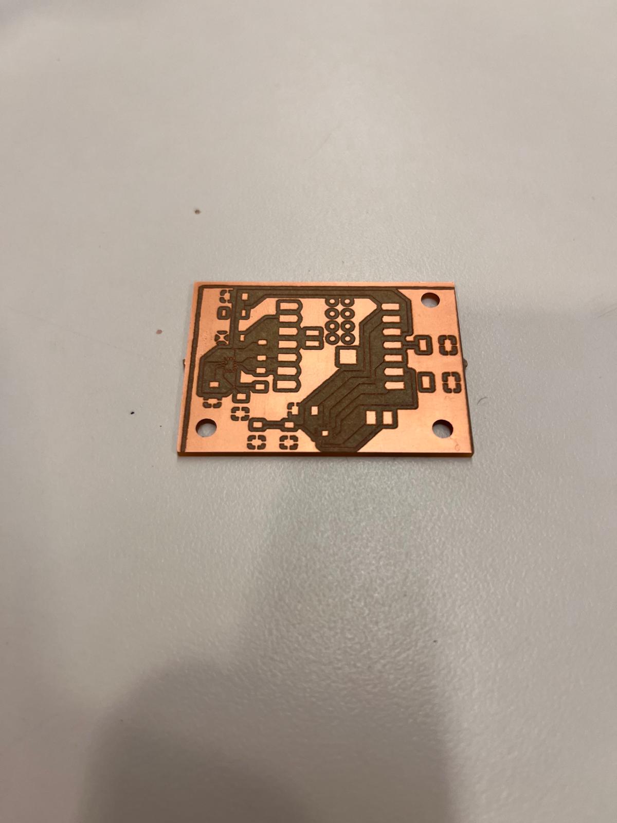
I designed my board in Kicad.
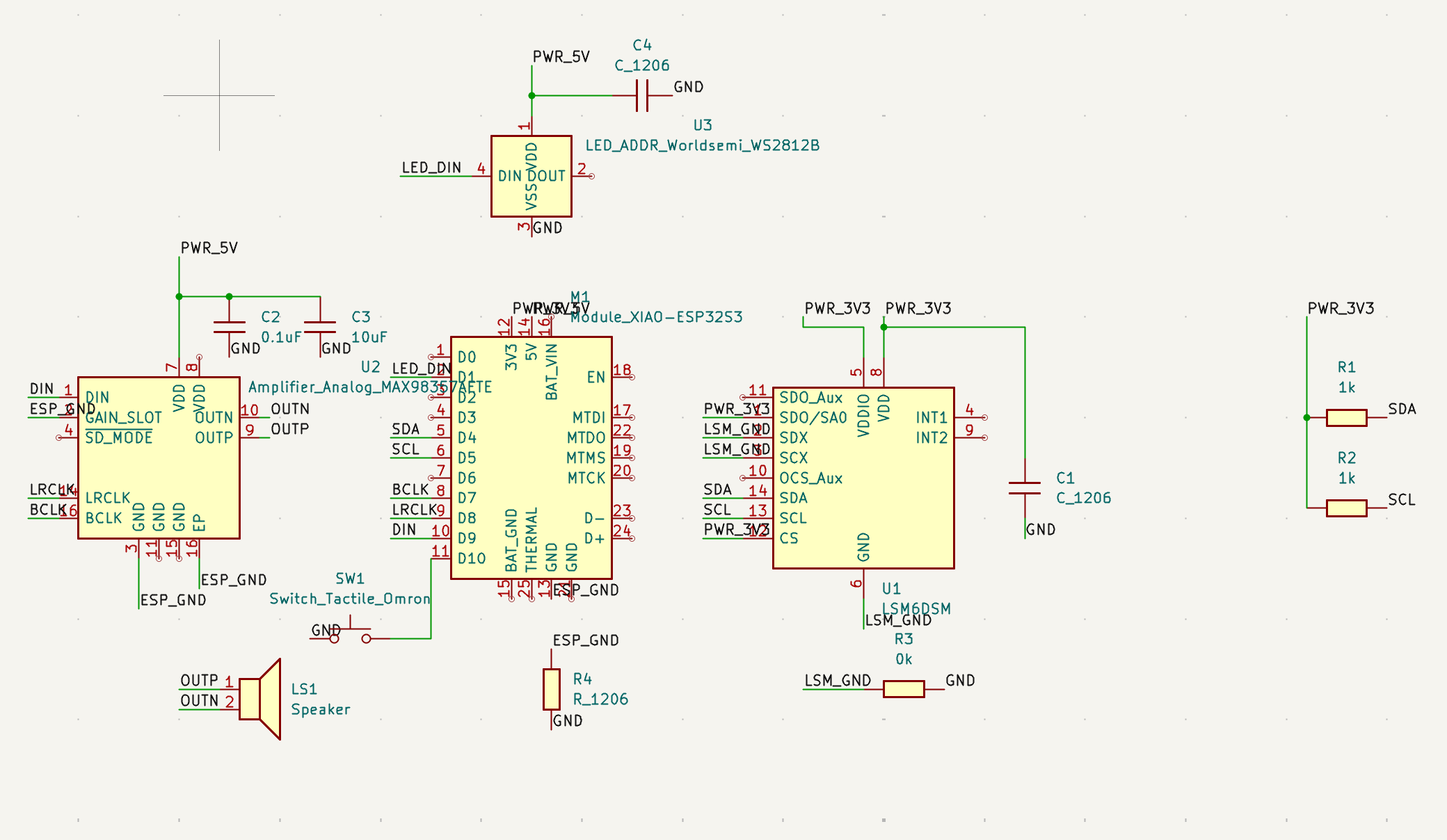
Here's the PCB I have:
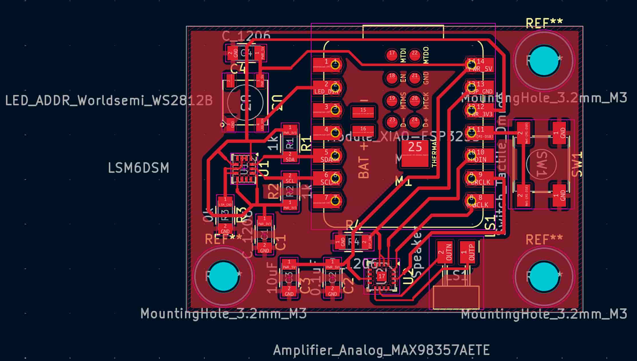
Electronics Production
I first used the Carvera machine to cut the shape of my board and drill the holes.
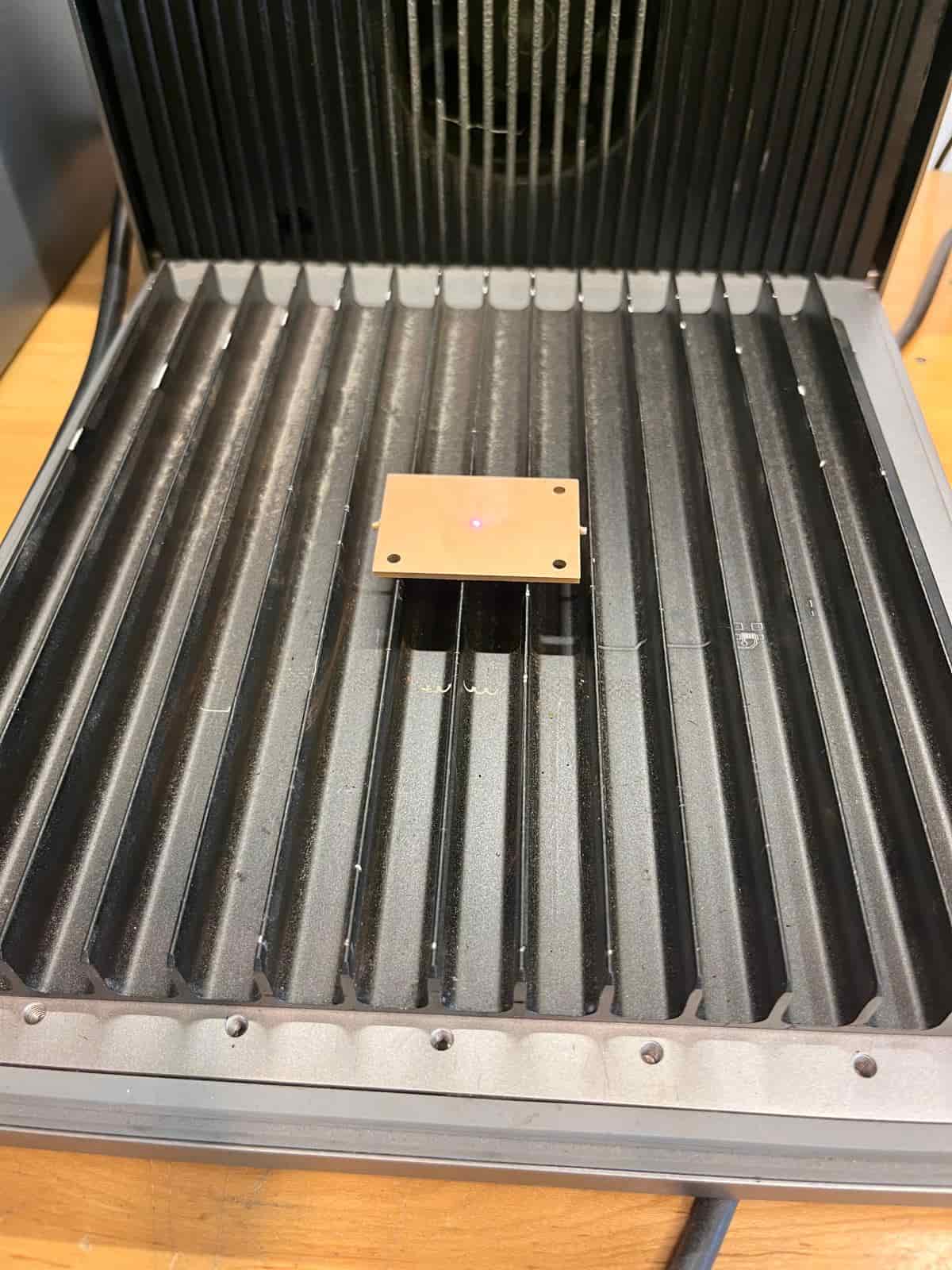
I then used the laser cutter to add the traces that it would engrave.
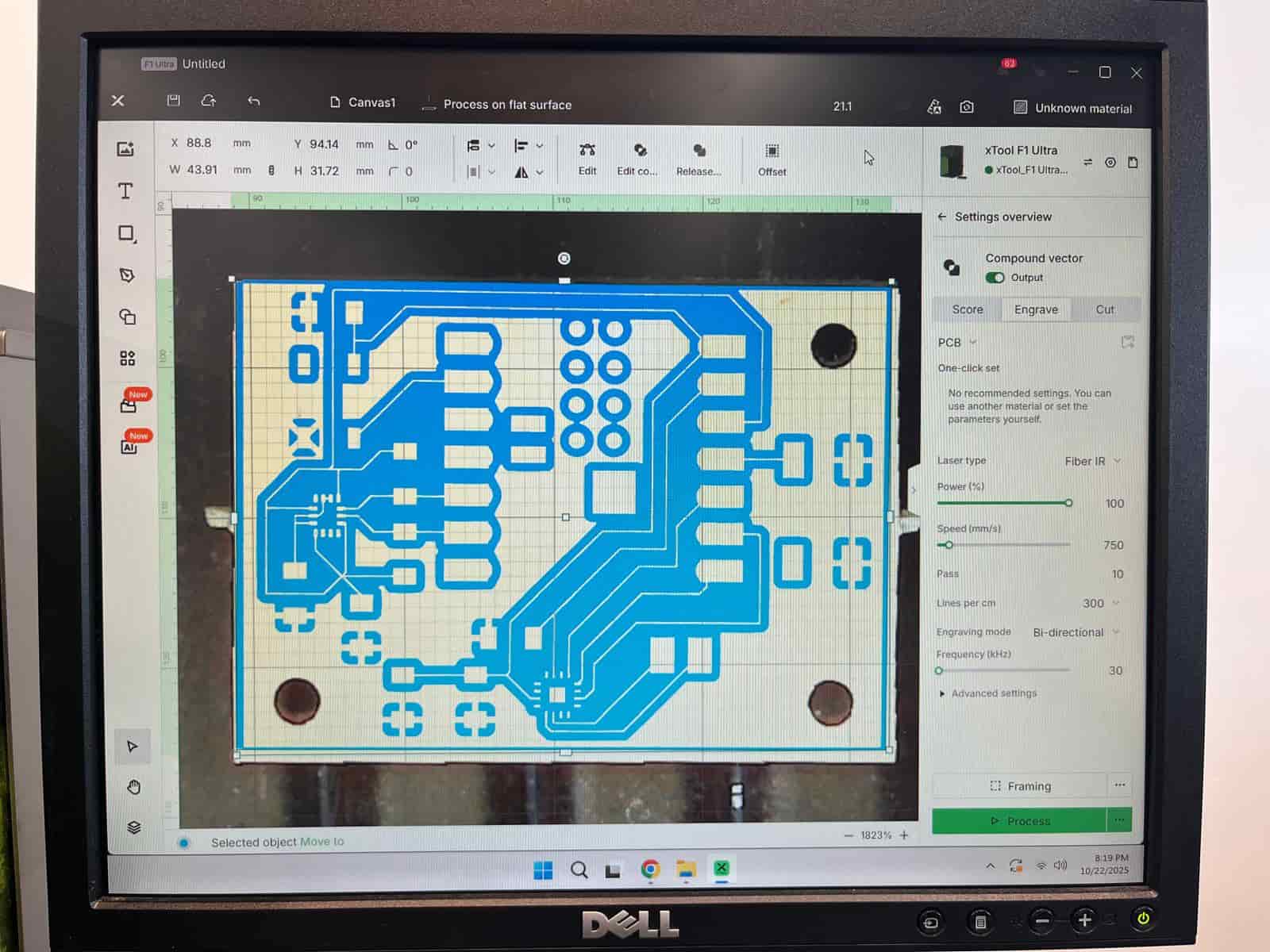
I used the following settings on the laser cutter:
- Laser Type: Fiber IR
- Power: 100%
- Speed: 750mm/s
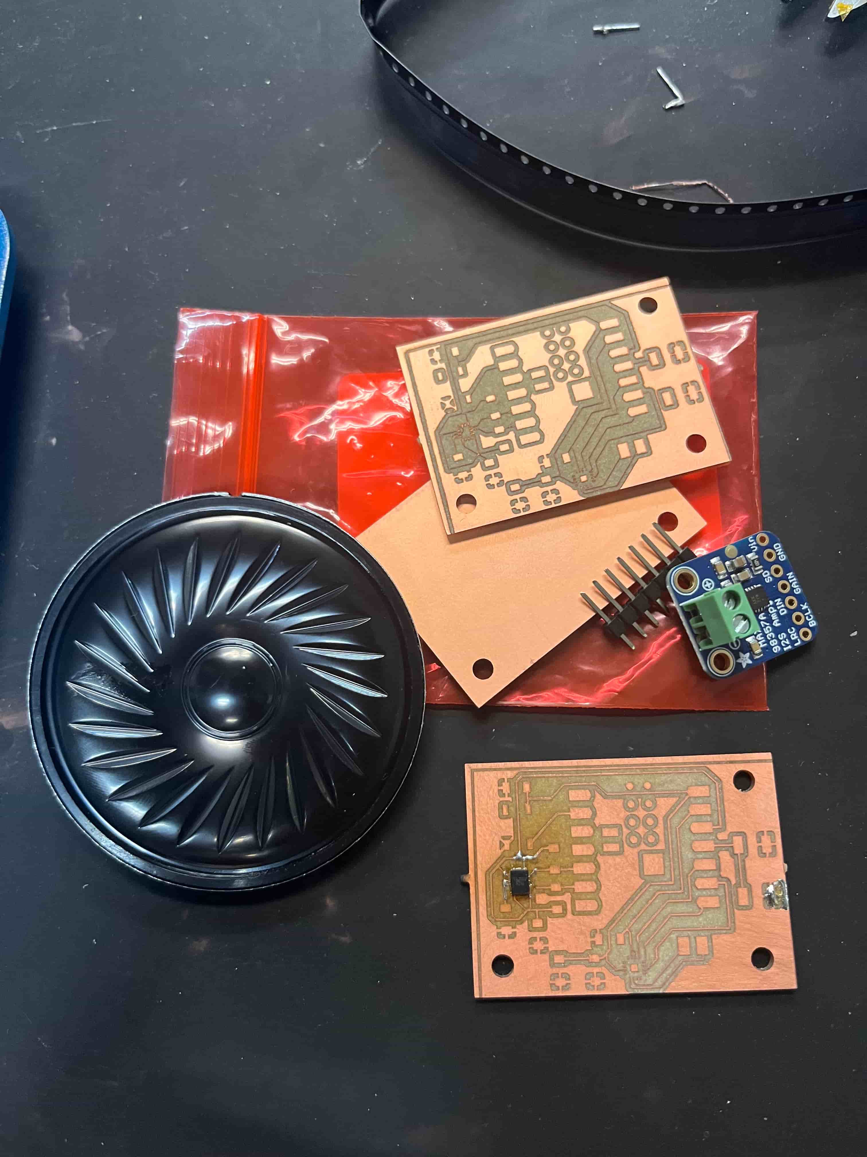
Here's the board that it cut out:
Soldering
With the help of Anthony, I learned how to properly apply solder paste and heat flow to solder small components onto my board. I would first apply a little bit of solder paste on each trace. Then I would use the tweezer to gently place the component on the paste, making sure the orientation is correct by checking with the datasheet. Usually there would be a sliced angle or a dot indicating the direction. However, this could be very subtle on small components so it took me a while to confirm that I was soldering the component correctly. Then, we use a lower medium to low speed with the temperature of the heat gun set between 270-330C. We place the heat gun slightly above the component and apply it until we see the solder paste begin to melt. With any extraneous paste flowing out or connecting two traces, we could use a wick to remove them.
One of the challenges is that when using the heat gun, I need to be careful not to apply heat for too long, since the FR1 board isn’t very heat-resistant and could get damaged.
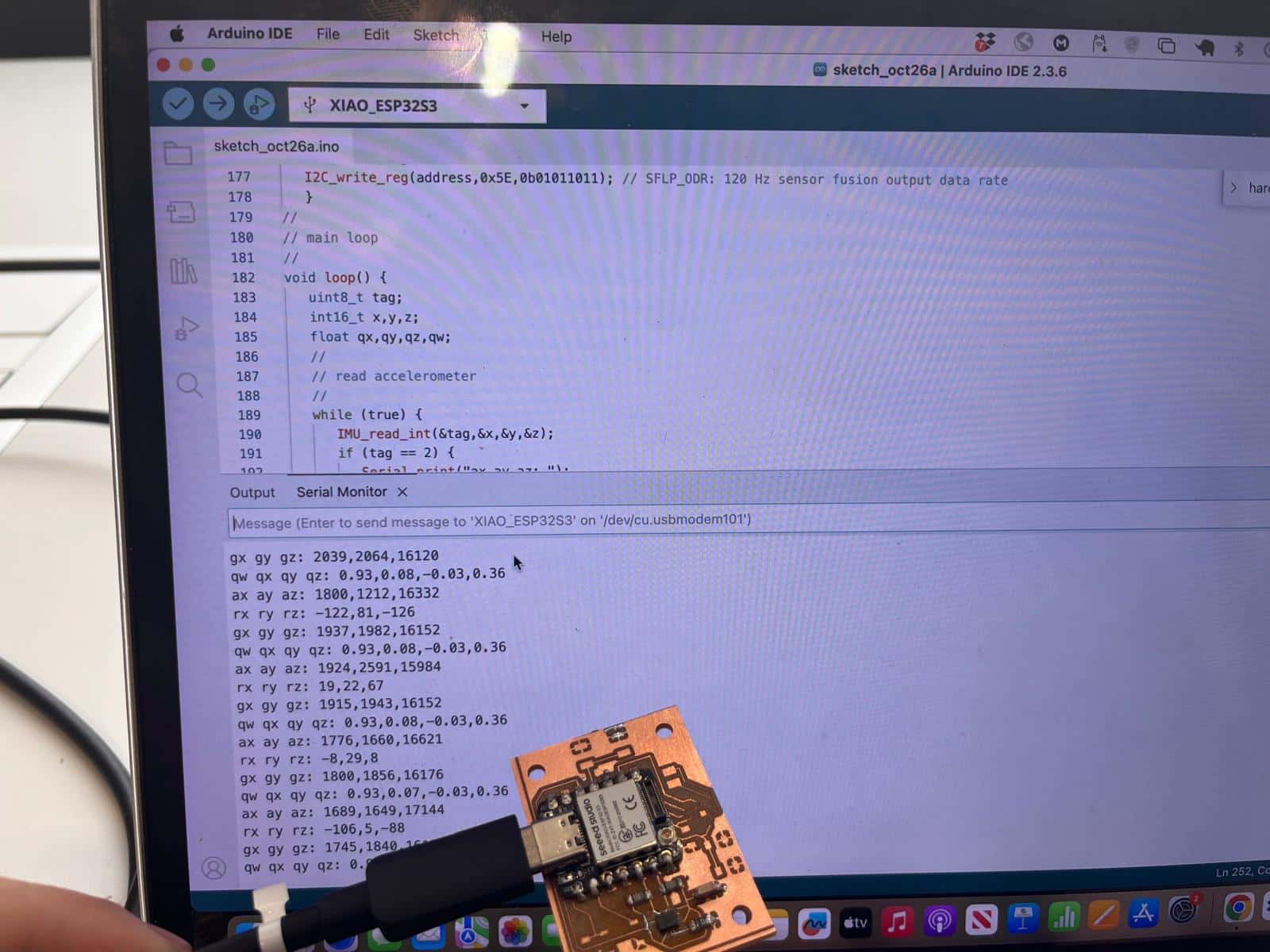
Input Test
I ran the sample code on the course website and was able to get varying inputs when I move the accelerometer around.
Resources and Acknowledgements
Tools used:
- ShopBot CNC
- Fusion 360
Thanks to Dan and Ceci for helping me immensely on this week's work.