Week 9
Output Devices
10/30/2025-11/05/2025
Group Assignment
Here's the link to our group assignment: group assignment
For the group assignment, we learned how to measure the power consumption of a speaker. We tried different frequencies and amplitude of the sound and how that affects the current and voltage.
Ideas
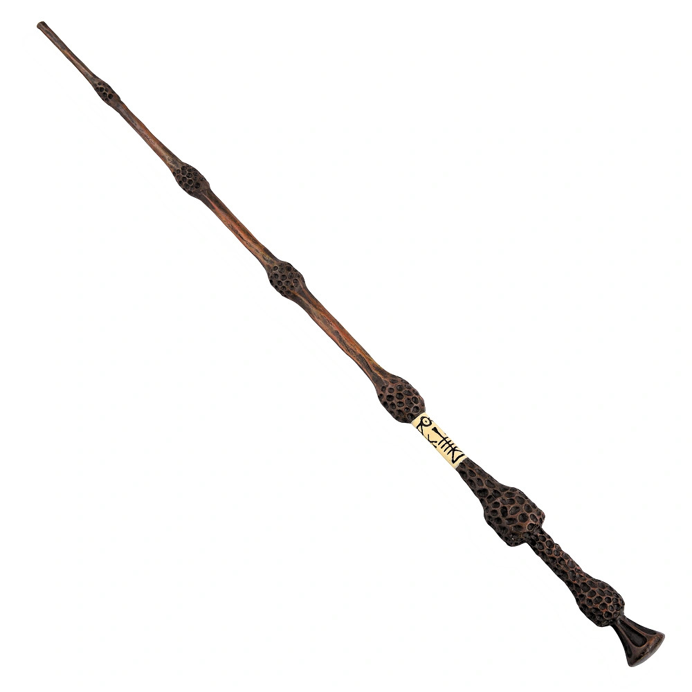
We are building on top of last week's assignment to add a speaker and RGB LED to my magic wand board.
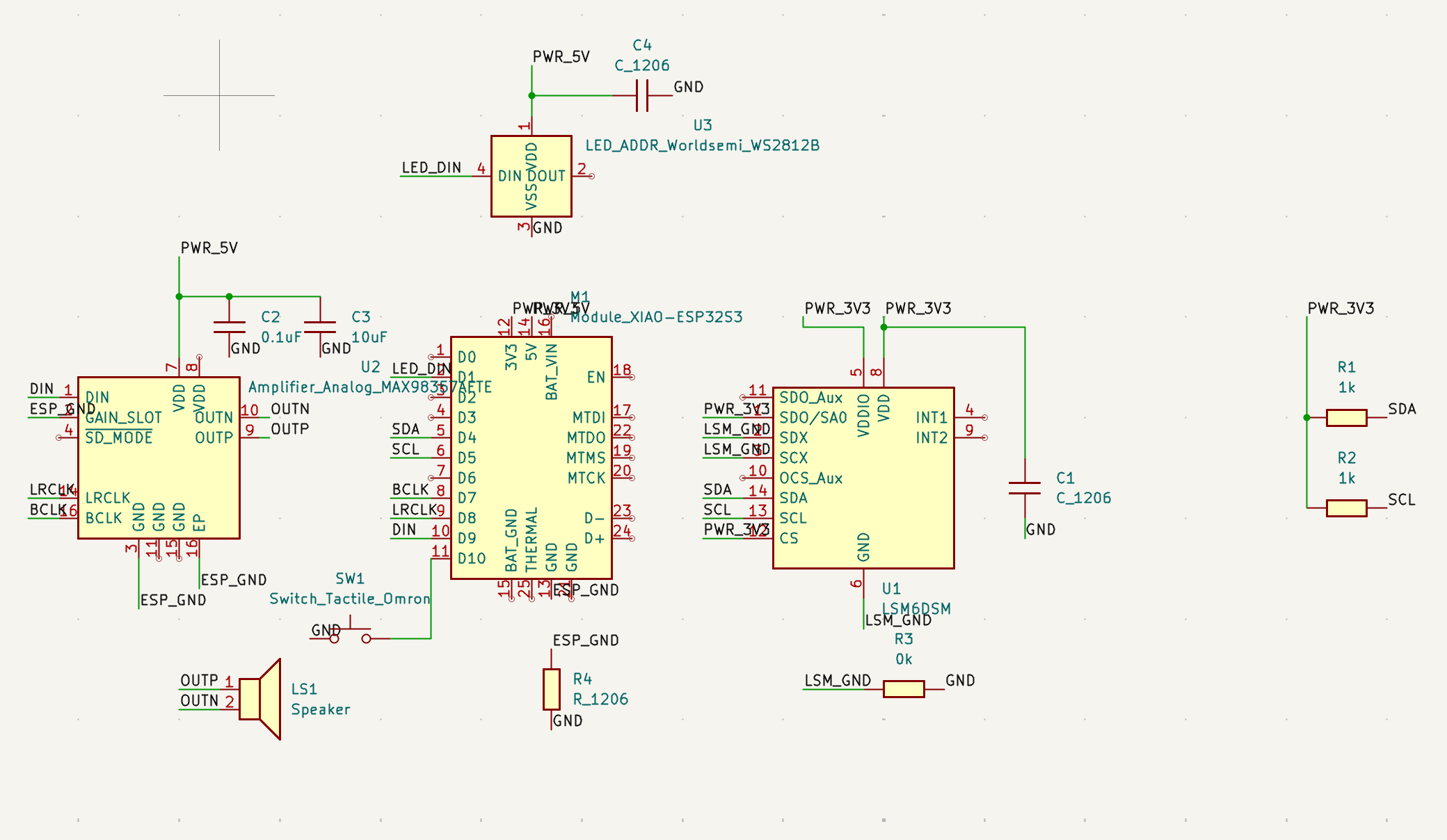
Here's the schematics from last week:
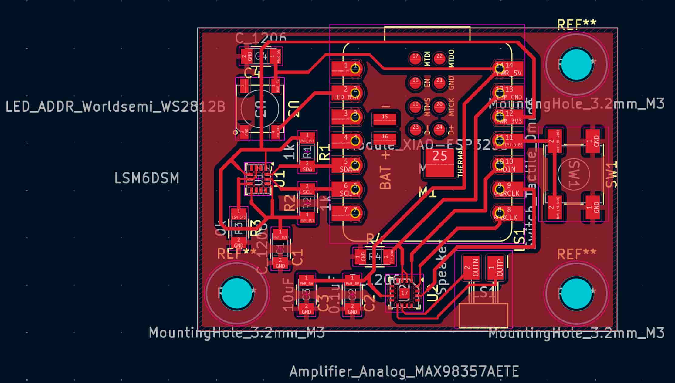
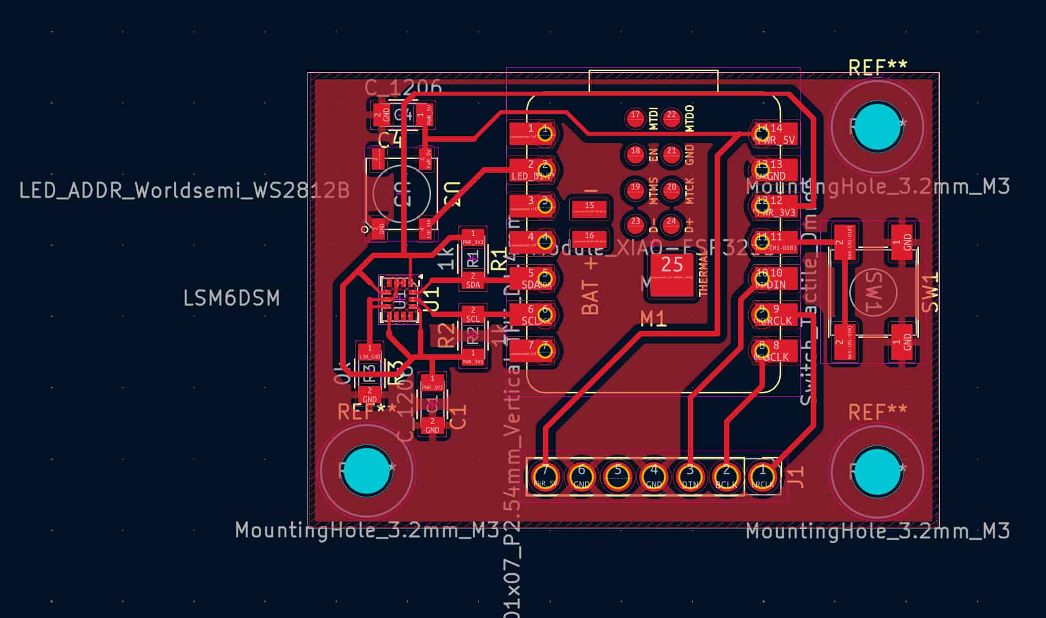
Here's the PCB design from last week as well:
Planning Ahead
One of the issue I encountered was not checking the inventory before starting to design my board. As a result, I was scrambling to find the parts I saw on the online inventory list but that actually don't exist in the physical inventory. I also didn't really want to change my design and print out another board as that would mean I need to spend time modifying my design, mill the board, and add the input device again. This is a clear sunk cost fallacy, and I was too deep into my original board to switch to a new design.
Thanks to Dimitar
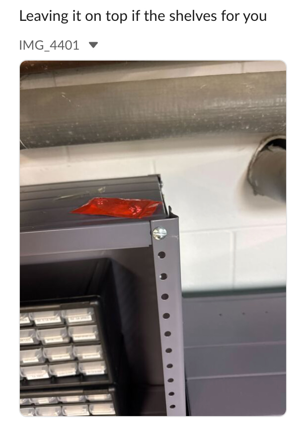
Fortunately, Dimitar found the last MAX98357 breakout board and left it in a hidden spot for me.
Feeling like Tom Cruise in Mission Impossible, I snuck down into the basement and retrieved the amplifier in the secret spot. Mission accomplished.
However, another decision quickly came after. My original design board was for the tiny component and not for the breakout board. I was too scared to desolder the amplifier from the breakout board. I decided to modify my design to adjust for the breakout board.
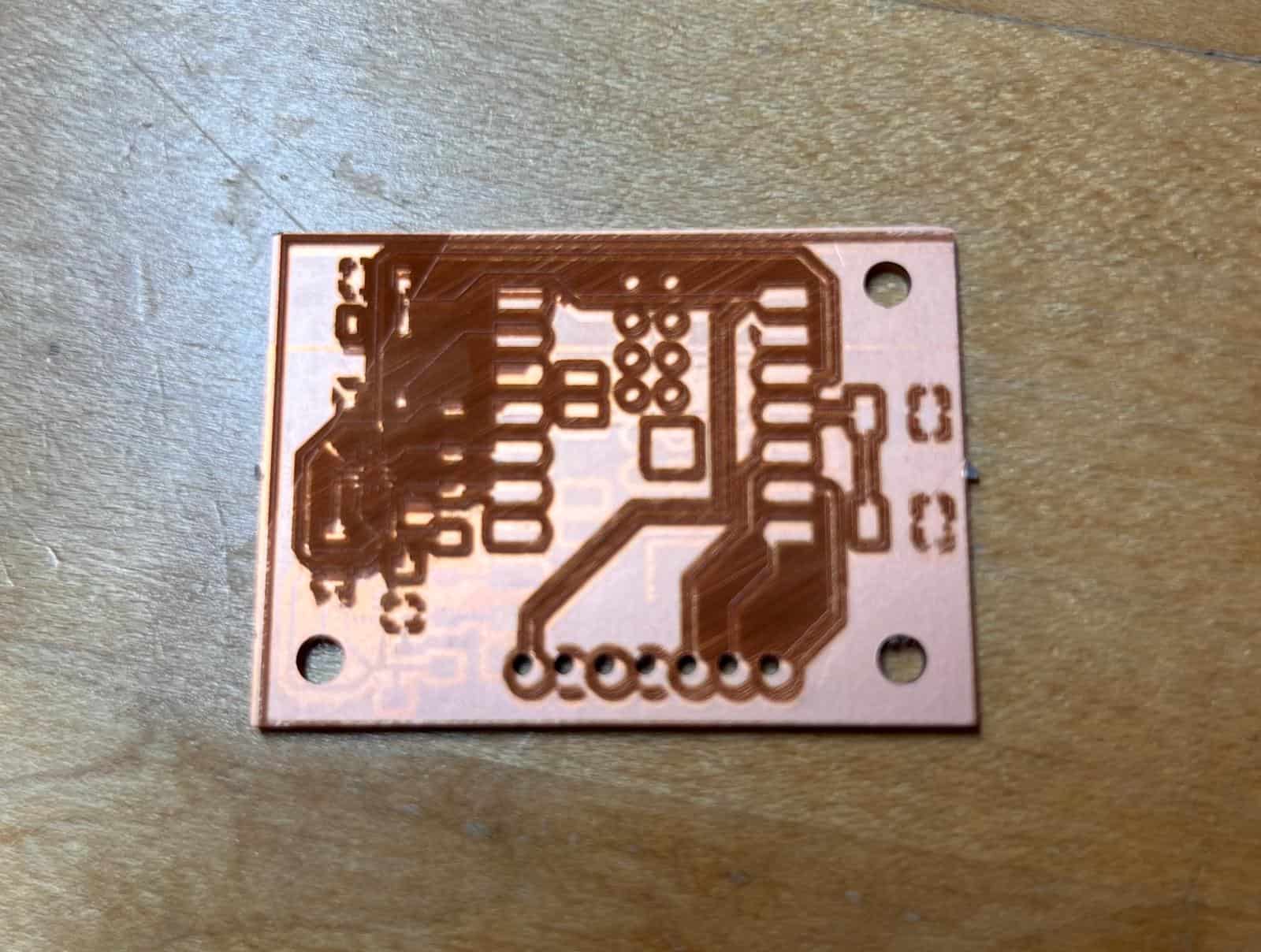
Here's my new PCB design with drill holes:
Laser Cutter Alignment Issue
The laser cutter had some alignment issues for the workflow. After cutting out the board and drilling the holes before using the laser cutter, I found that even when aligning the designed holes on the drilled holes through the software, there are some offsets as shown in the image. The laser engraved traces aren't evenly spaced around the drilled holes. After trying out a few different manual offset configurations, I found that moving the image to the left and up six times through the left arrow key and up arrow key helps the problem a little bit.
Soldering
I used the heat gun to desolder the amplifier from its breakout board following this tutorial. Remember to use a lot of flux.
I then used the heat gun to solder it onto my board. Thanks to the guidance of Anthony, he helped me remove some of the solder joints connected together, which could lead to a short. I also used the solder wick to take out some of the extra solder flowing out of the amplifier.
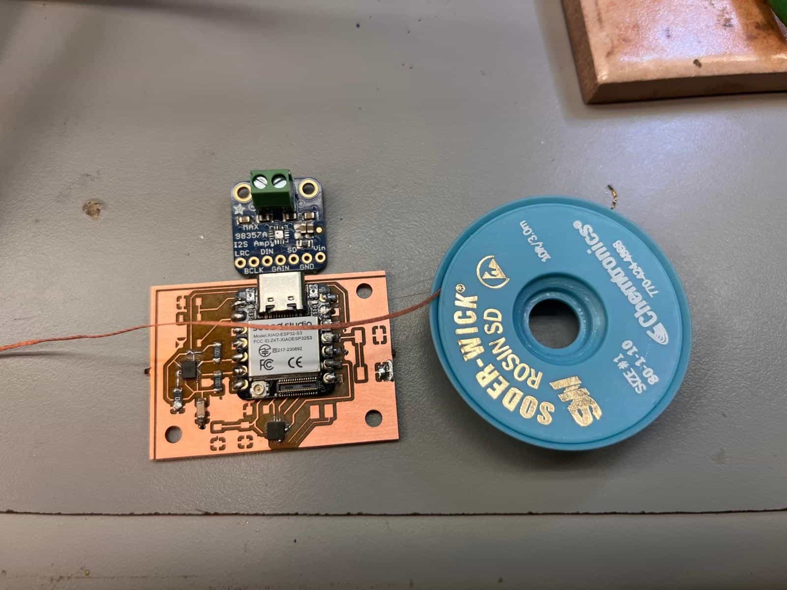
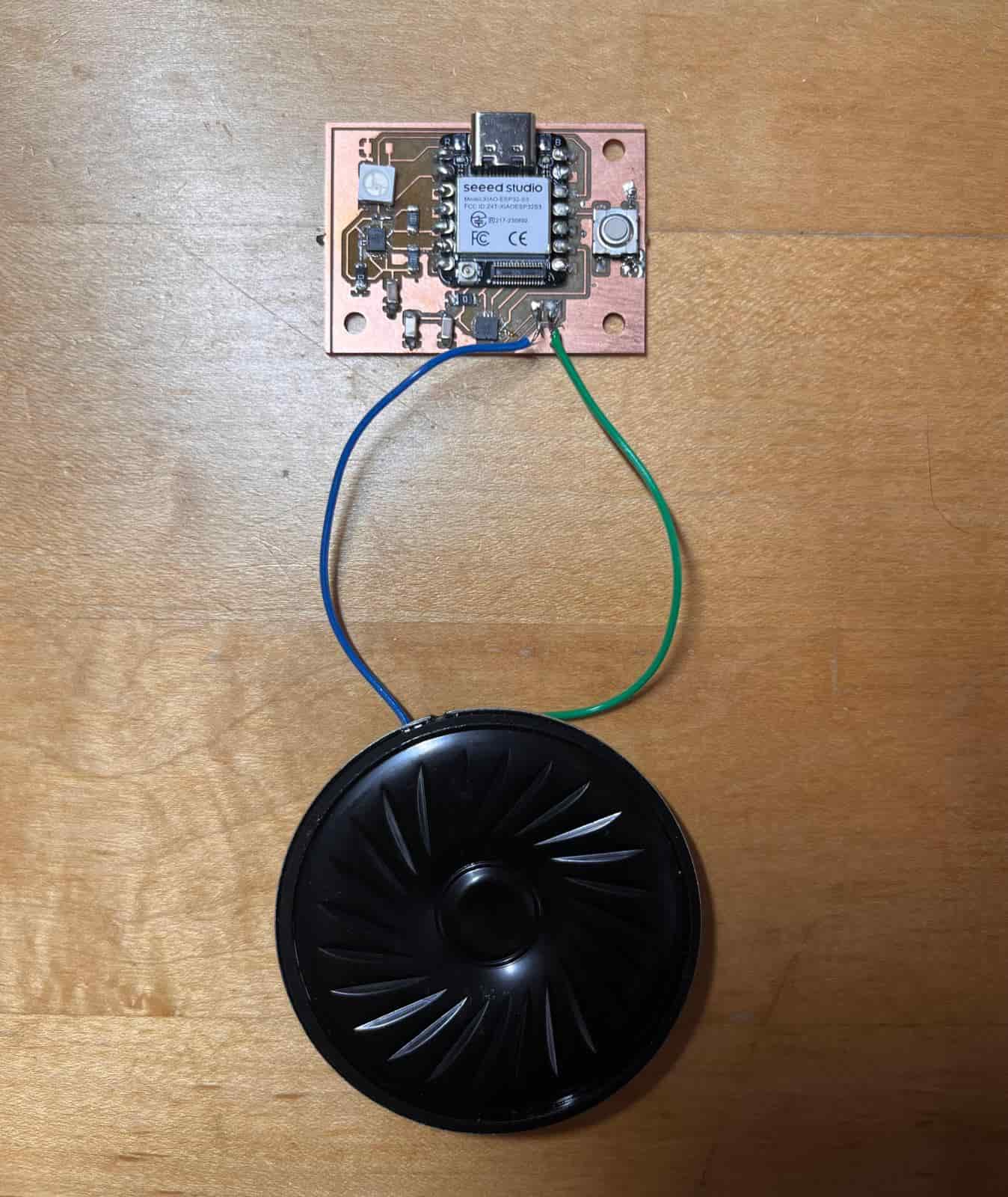
I then soldered on a button and a RGB LED, which was out of stock but thanks to Matti for gifting me two RGB LEDs that he purchased himself. Here's what the board with all of the components look like:
Testing the code
I converted the sample code from Python to Arduino using ChatGPT. The LED is super bright:
#include <Adafruit_NeoPixel.h>

#define PIN      2     // LED connected to pin 2
#define NUM_LEDS 1     // Only 1 LED
#define DELAY_MS 1     // Delay between updates

Adafruit_NeoPixel strip(NUM_LEDS, PIN, NEO_GRB + NEO_KHZ800);

void setup() {
  strip.begin();
  strip.show(); // Initialize LED to off
}

void loop() {
  int Max = 255;

  // Fade in red
  for (int i = 0; i <= Max; i++) {
    strip.setPixelColor(0, strip.Color(i, 0, 0));
    strip.show();
    delay(DELAY_MS);
  }

  // Fade to yellow (red + green)
  for (int i = 0; i <= Max; i++) {
    strip.setPixelColor(0, strip.Color(Max, i, 0));
    strip.show();
    delay(DELAY_MS);
  }

  // Fade to green
  for (int i = Max; i >= 0; i--) {
    strip.setPixelColor(0, strip.Color(i, Max, 0));
    strip.show();
    delay(DELAY_MS);
  }

  // Fade to cyan (green + blue)
  for (int i = 0; i <= Max; i++) {
    strip.setPixelColor(0, strip.Color(0, Max, i));
    strip.show();
    delay(DELAY_MS);
  }

  // Fade to blue
  for (int i = Max; i >= 0; i--) {
    strip.setPixelColor(0, strip.Color(0, i, Max));
    strip.show();
    delay(DELAY_MS);
  }

  // Fade to magenta (blue + red)
  for (int i = 0; i <= Max; i++) {
    strip.setPixelColor(0, strip.Color(i, 0, Max));
    strip.show();
    delay(DELAY_MS);
  }

  // Fade to white
  for (int i = 0; i <= Max; i++) {
    strip.setPixelColor(0, strip.Color(i, i, i));
    strip.show();
    delay(DELAY_MS);
  }

  // Blink off and on
  strip.setPixelColor(0, strip.Color(0, 0, 0));
  strip.show();
  delay(250);

  strip.setPixelColor(0, strip.Color(Max, Max, Max));
  strip.show();
  delay(250);

  // Fade out to off
  for (int i = Max; i >= 0; i--) {
    strip.setPixelColor(0, strip.Color(i, i, i));
    strip.show();
    delay(DELAY_MS);
  }
}
Here's the LED working:
Thanks to Ben
I have been carrying my board around wrapped in a piece of tissue. Ben offered me a zipped bag to keep my board, which proved crucial in two ways.
Last Wednesday was pouring and I had to run between different places and even with the umbrella, my bag got a little wet. If I still had my board in the tissue, it would likely have gotten wet. But with it safe in the zipped bag, I felt a lot safer.
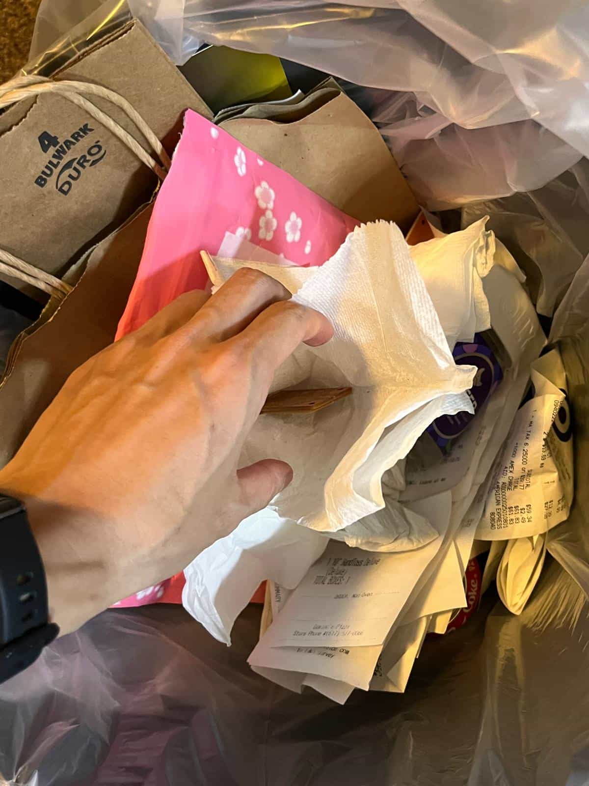
Another issue with wrapping it in tissue is I thought it was trash and threw it in my trash can. Only when I wanted to complete the documentation did I realize that I had kept the failed board in the tissue still. Luckily I haven't thrown out the trash yet so I got it back to fill up some space for my documentation.
Resources and Acknowledgements
Tools used:
- Carvera Desktop CNC
- xTool F1 Ultra
- Gerber2img
- KiCad
- Arduino IDE
- ChatGPT