Overview
This week, we learned about electronics design – using EDA (Electronic Design Automation) tools to design our own circuit boards. The assignment was:
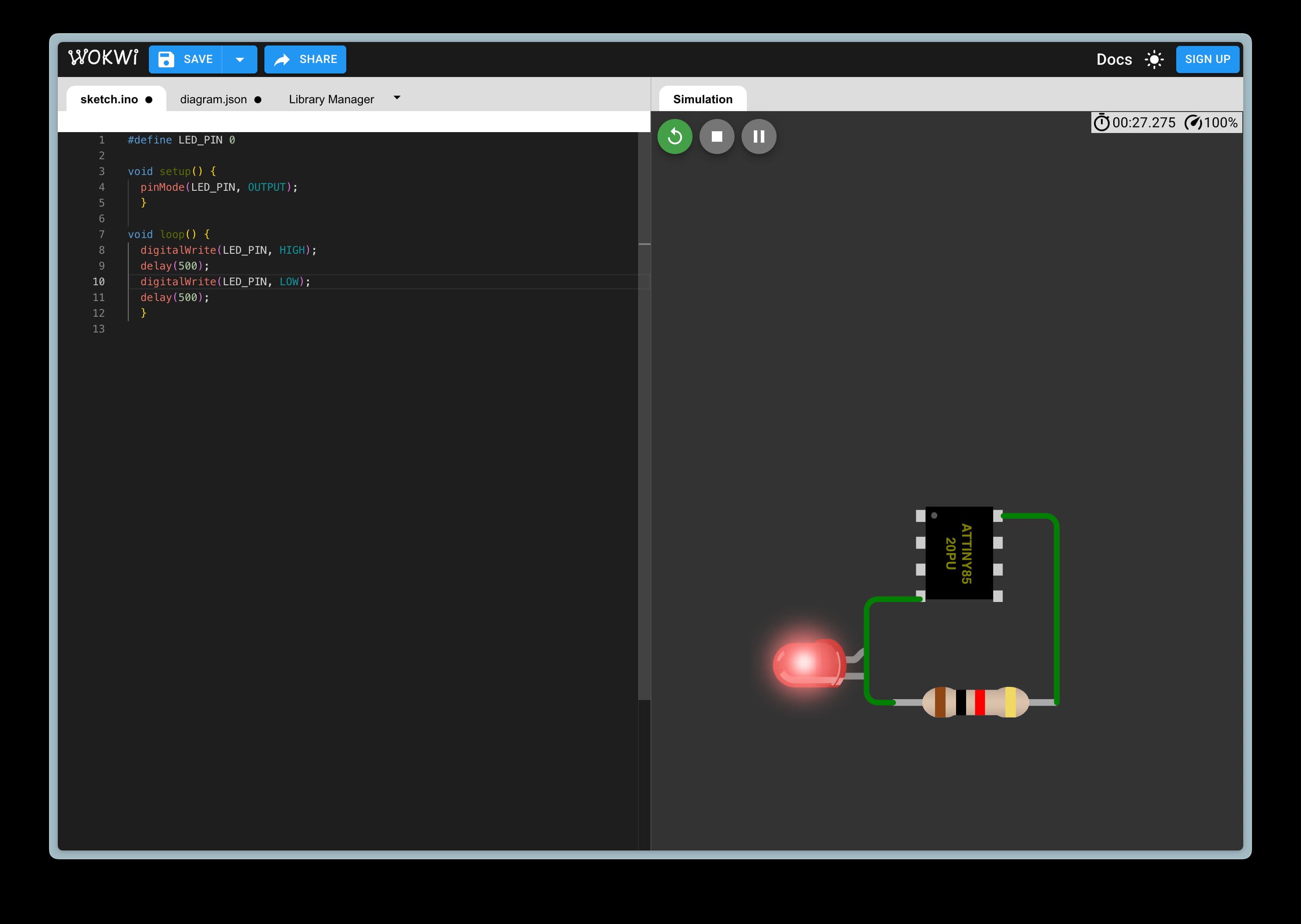
- simulate a circuit
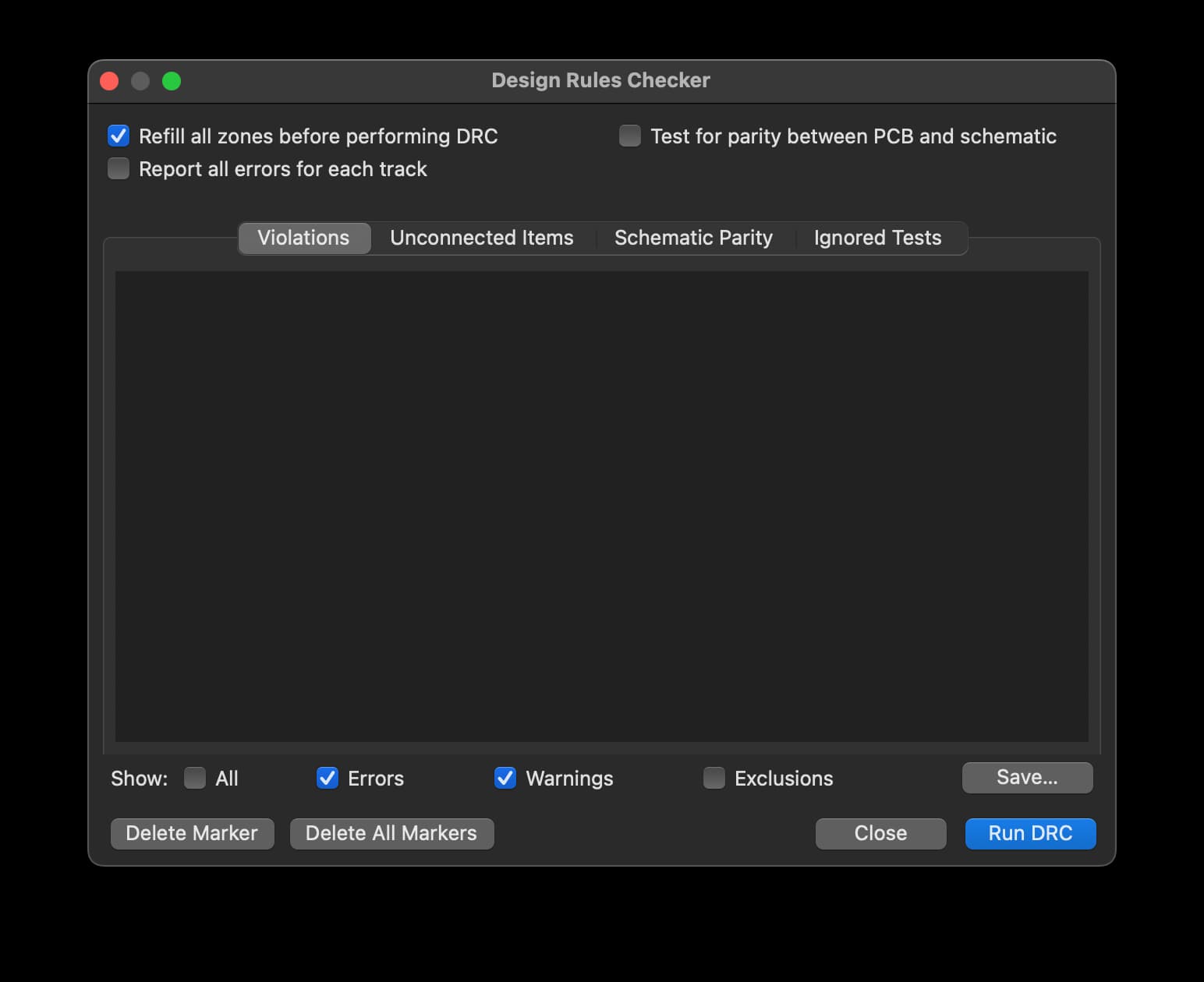
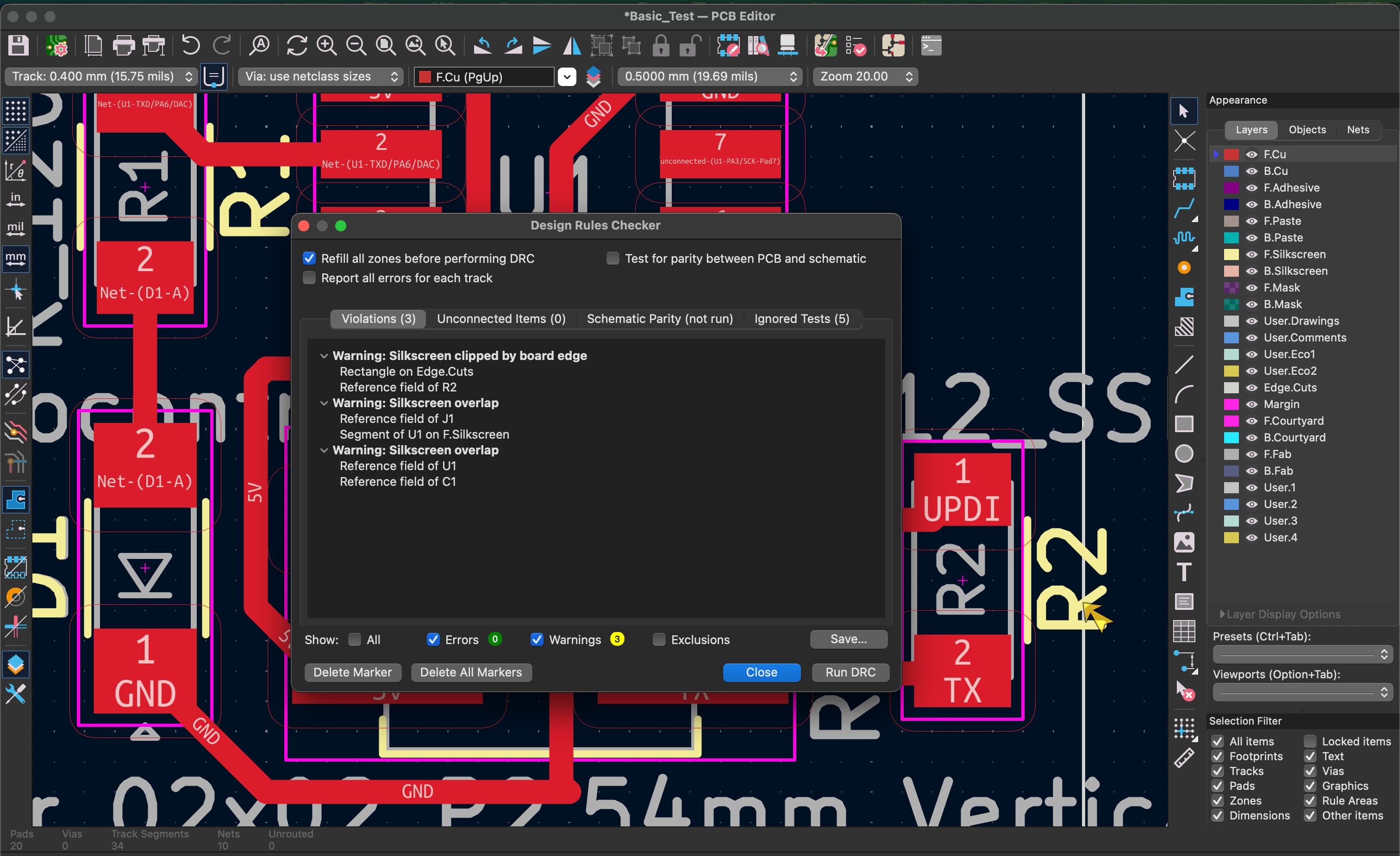
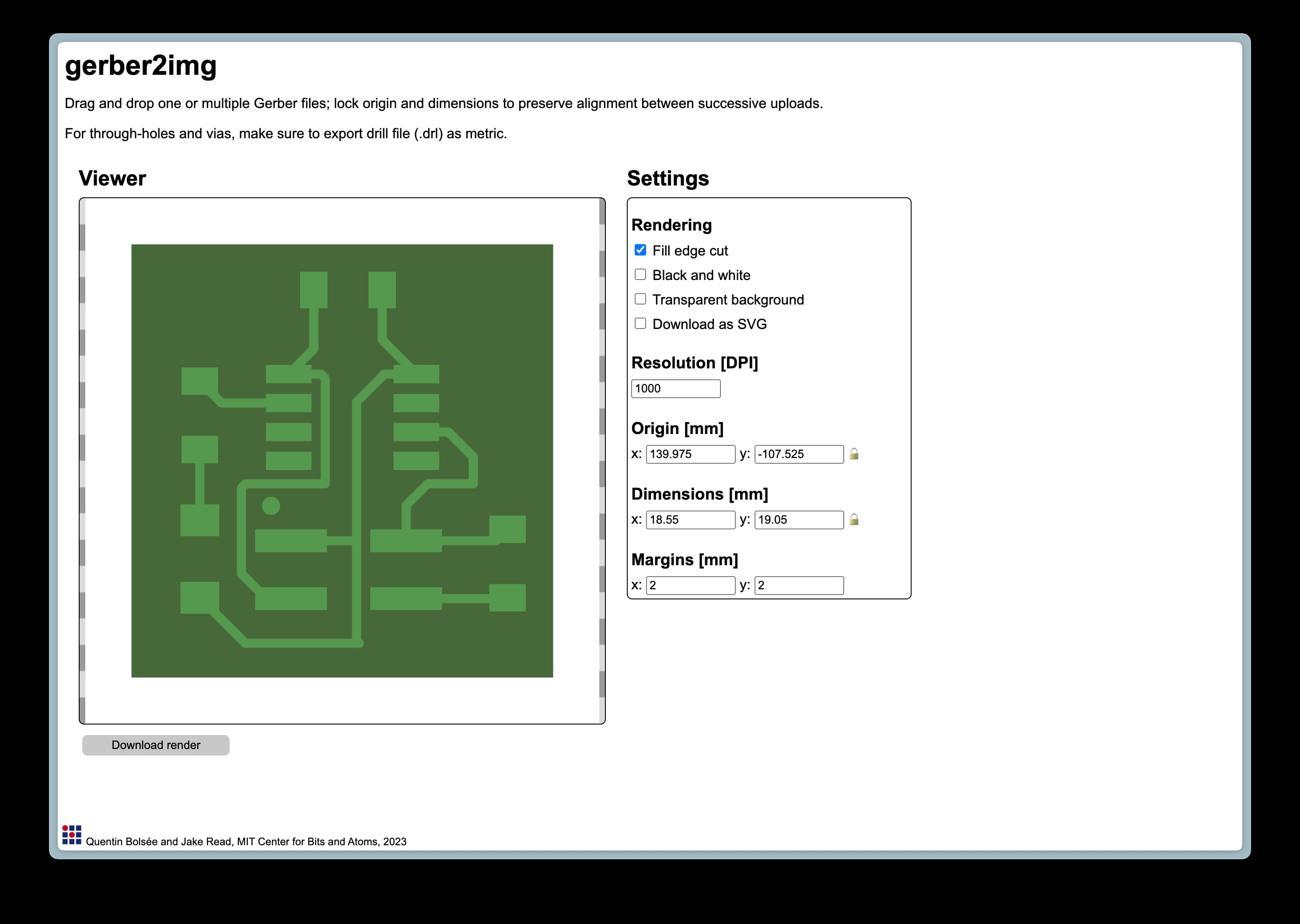
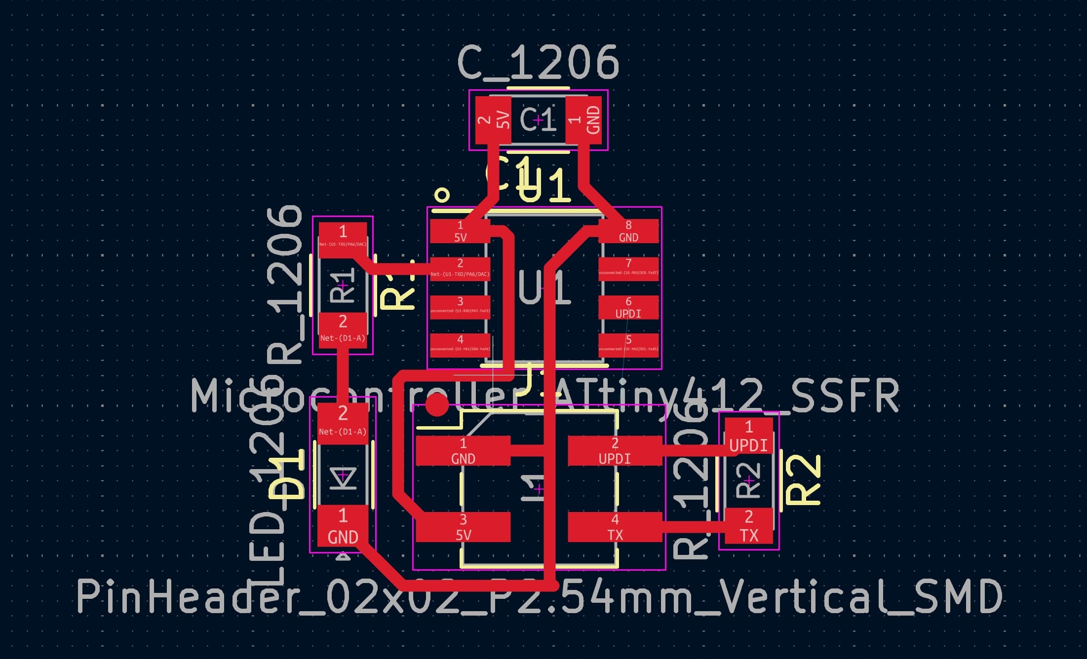
- use an EDA tool to design an embedded microcontroller system using parts from the inventory, and check its design rules for fabrication
Project Files & Links
Group Assignment
Our group assignment was:
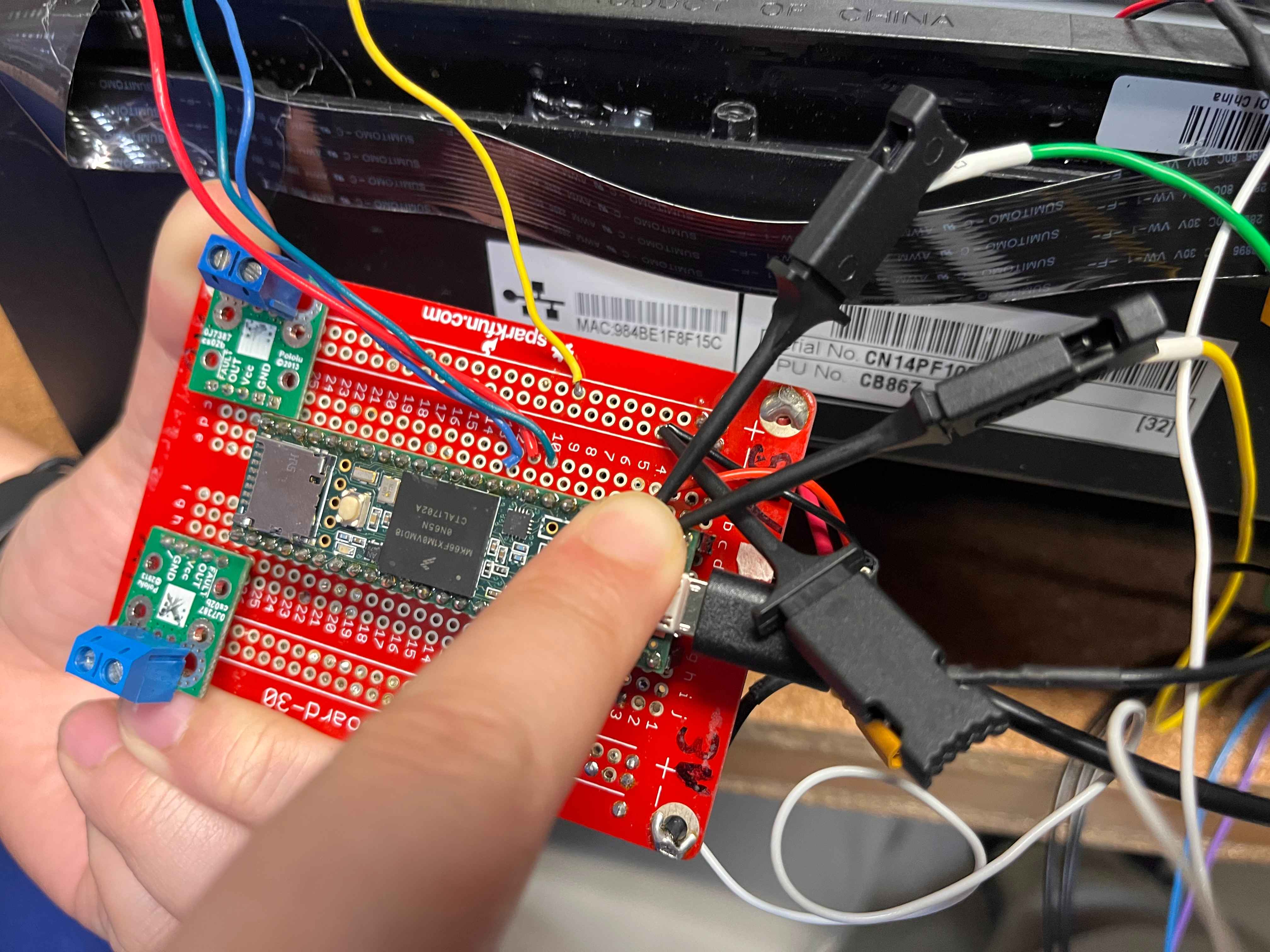
"use the test equipment in your lab to observe the operation of an embedded microcontroller"
You can find what our group did to complete it here.
Notes From a Electronics 101 Crash Course
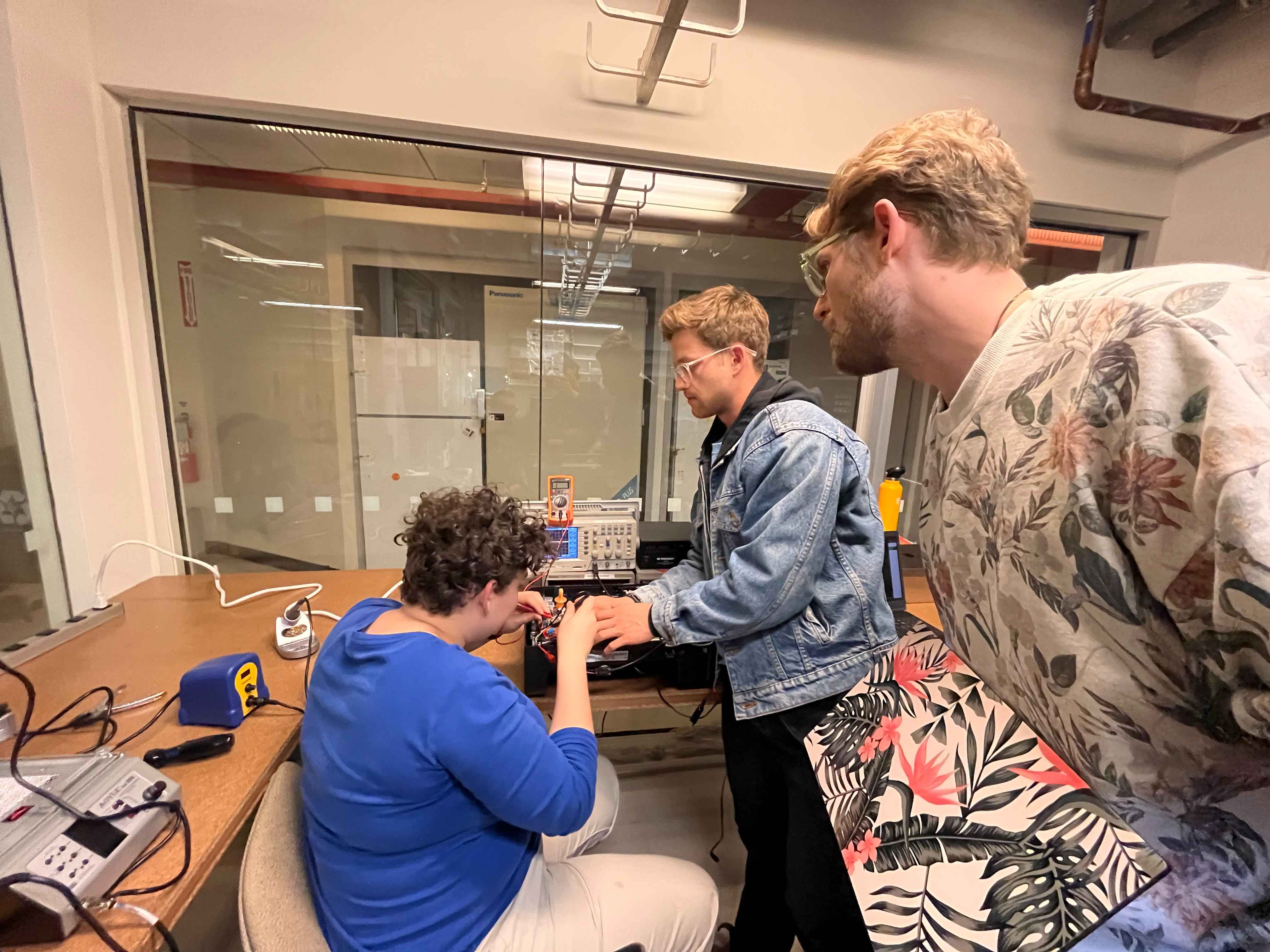
Ceci and Ben led a little EE-101 session downstairs in which they demonstrated how to use a multimeter, oscilloscope and Mixed signal logic analyzer. I took notes and have included them here. They also covered some basic circuitry topics and best practices for debugging electrical systems.
Multimeter
A multimeter is a versatile tool used to measure voltage, current, and resistance. It can also check continuity—when you turn the dial to the setting marked with a small speaker or soundwave icon, the device will emit a beep if two points are electrically connected.
In general, the red probe is positive and the black probe is negative (ground). For an LED, this means red connects to the anode and black to the cathode. Reversing these will prevent it from lighting or cause an error. When expecting measurements above 10A, move the red probe to the port on the left side of the multimeter for safety.
The core units measured are:
- Ohms (Ω) for resistance
- Amps (A) for current
- Volts (V) for voltage
- Watts (W) for power (a measure of energy per second)
Power is calculated by the equation P = I × V, where current (I) and voltage (V) combine to express total power. Resistance can be understood as how difficult it is to push current through a conductor.
When measuring, select a range close to your expected value to ensure accuracy.
Series vs. Parallel Circuits
In a series circuit, components are connected end-to-end—current remains constant throughout, but voltage drops after each component. In a parallel circuit, each branch receives the same voltage, but current divides based on the resistance of each path. Understanding this distinction is key for predicting how your circuit will behave under load.
Circuit Components
Common components include the microcontroller (MCU), LEDs, batteries (BAT), and speakers (S). A transistor functions as a switch: it connects two points only when a current is applied to its control pin (base or gate).
High vs. Low Logic
Digital systems work in binary—either HIGH (1) or LOW (0). These correspond to the presence or absence of voltage. In some cases, a circuit may use low-side logic, where a signal turning "off" (0) actually powers a device "on." This can be confusing, so it's best not to overthink it at first; the important part is recognizing how voltage states correspond to on/off behavior.
Measuring Current
To measure current, you must place the multimeter in series with the circuit—essentially making the meter part of the circuit so that the current flows through it. This means disconnecting the circuit at the point of measurement and inserting the probes.
If you don't, you risk shorting the circuit or getting inaccurate readings. Current measurement is more complex, especially on a printed circuit board (PCB), where you may need to cut a copper trace and reinsert the measurement point.
Current flows from the power source (positive/red) through the load and back to ground (negative/black). Because current measurement requires the flow to pass through the multimeter, you'll often need a third wire or connection to maintain continuity.
Why measure current? It's essential for understanding power consumption. While datasheets may list expected draw (for example, a sensor at 100 mA and a processor at 100 mA), the combined total can differ in practice. Measuring directly allows you to validate these estimates and ensure the circuit behaves as designed.
Oscilloscope
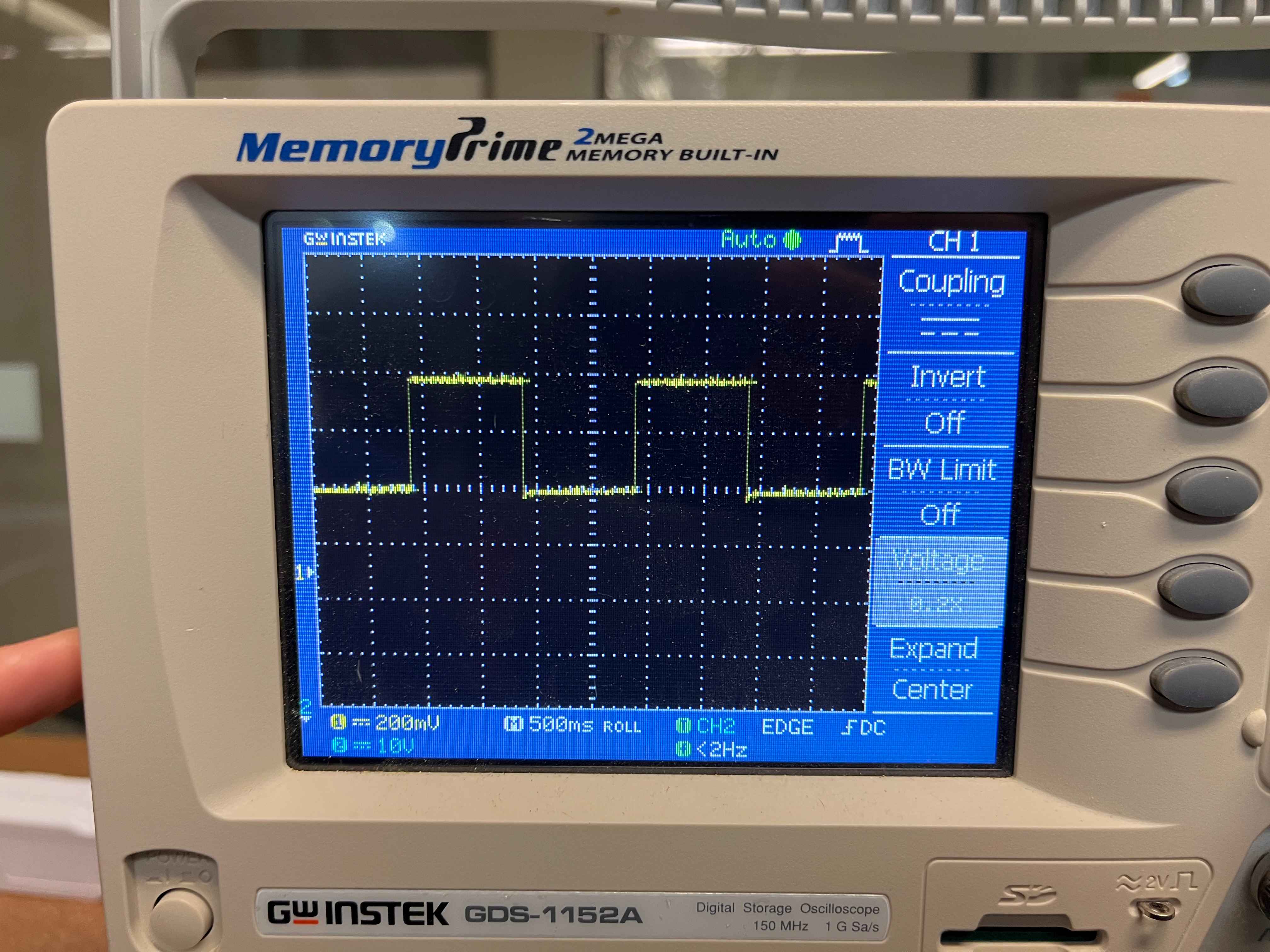
An oscilloscope measures voltage over time, making it ideal for observing analog or fluctuating signals. It connects to both ground and the signal line, displaying how voltage levels change dynamically. For example, probing the logic line of a blue LED will reveal the waveform of its voltage transitions—effectively showing how the microcontroller drives the light.
Logic Analyzer
A logic analyzer is used for digital signals, typically reading binary states (0s and 1s) over time. It connects to the serial port of a board—commonly RX (receive) and TX (transmit) pins—but any digital pin can technically be used if synchronized properly. Some systems also use clock lines to maintain timing accuracy.
For this project, the RX1 and TX1 lines represent serial communication channels, which constantly toggle between 1 and 0 as data is transmitted and received.
Experiment and Observations
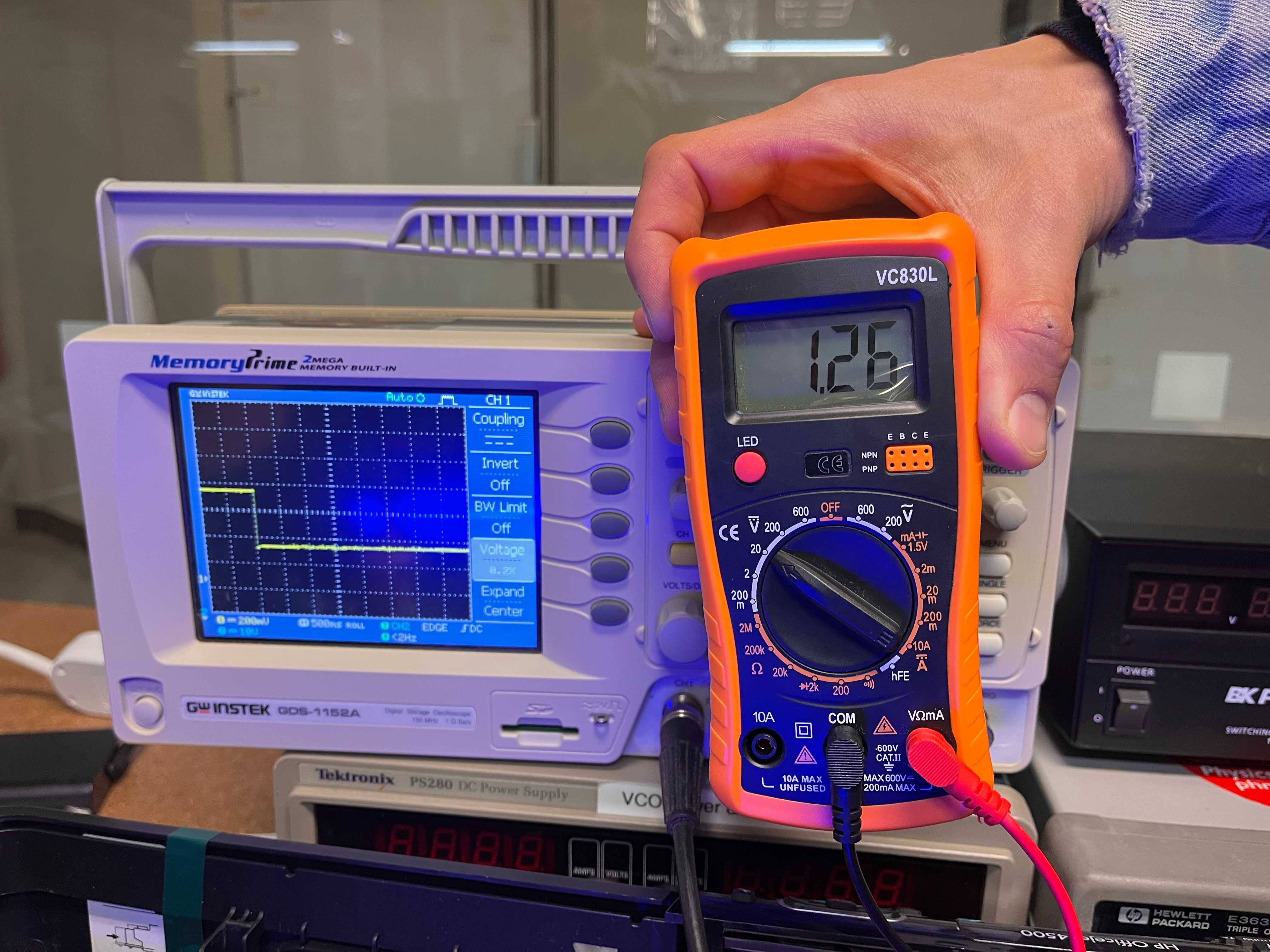
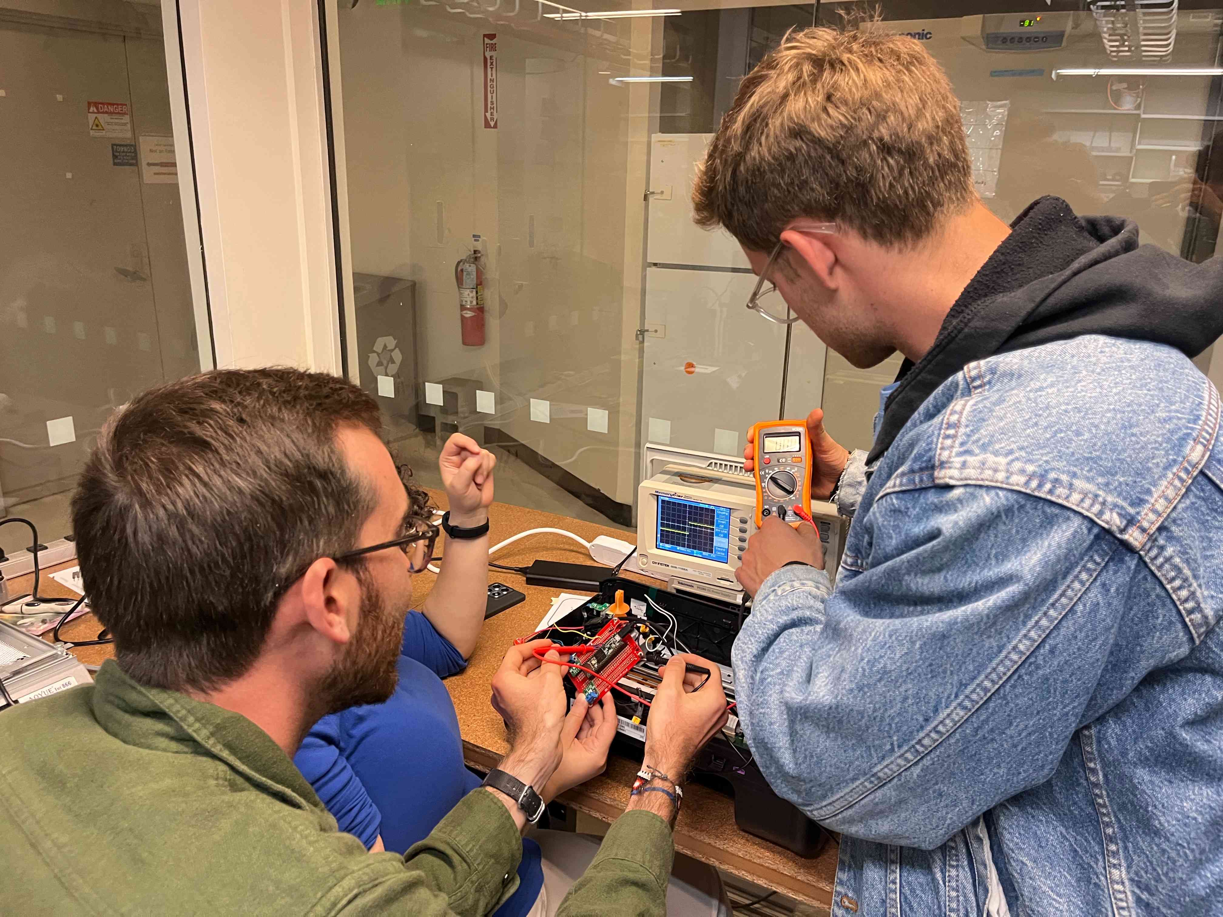
We compared readings between the multimeter and the oscilloscope while probing the blue LED from Ben's project. Both instruments showed consistent voltage readings: alternating between 3.3V and approximately 1.28V.
The drop occurs due to the internal resistor in the circuit, which absorbs the excess voltage that the LED does not use. Every LED has a forward voltage—a minimum voltage required for it to light up (typically around 0.6V for small LEDs). Anything beyond that threshold must be dissipated as heat through a resistor. Without one, the LED would draw excessive current and burn out.
The resistor can be placed either before or after the LED in the circuit; what matters is that it's in the same loop. According to Kirchhoff's Law, the total voltage drop across all components in a closed circuit must equal zero. The resistor ensures this balance by converting excess energy into heat safely.
You can imagine it like water flowing through a pipe. The LED is a narrow section that only lets a limited amount of "flow" through, while the resistor acts like a flexible section that absorbs pressure. Squeezing the pipe before or after the gauge changes the pressure distribution but achieves the same effect: the total flow slows, protecting the system.
Details
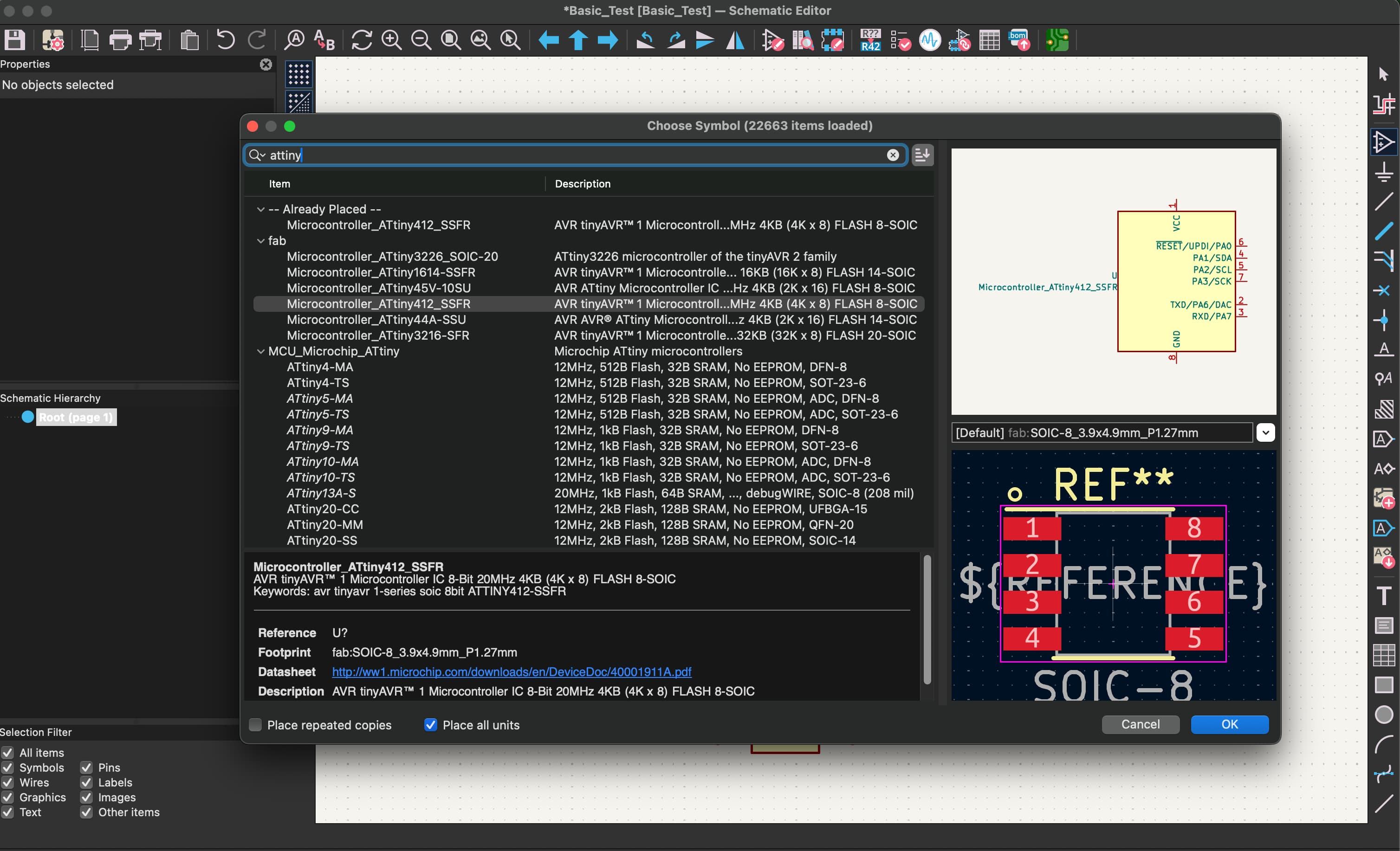
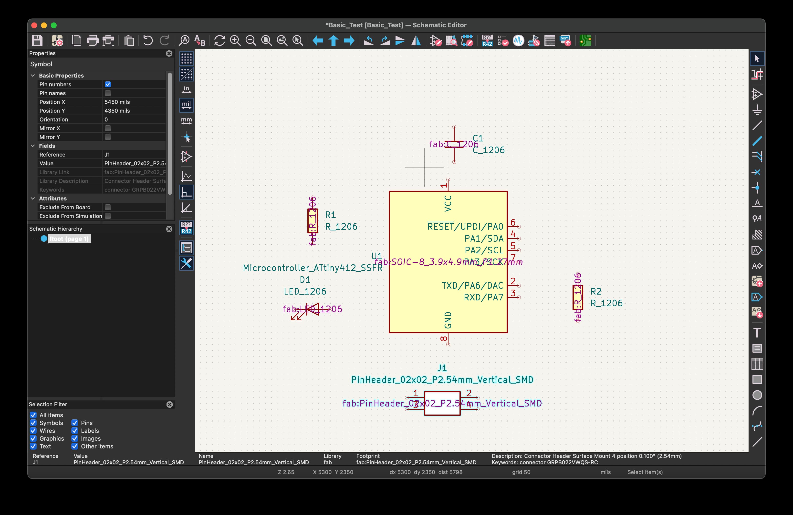
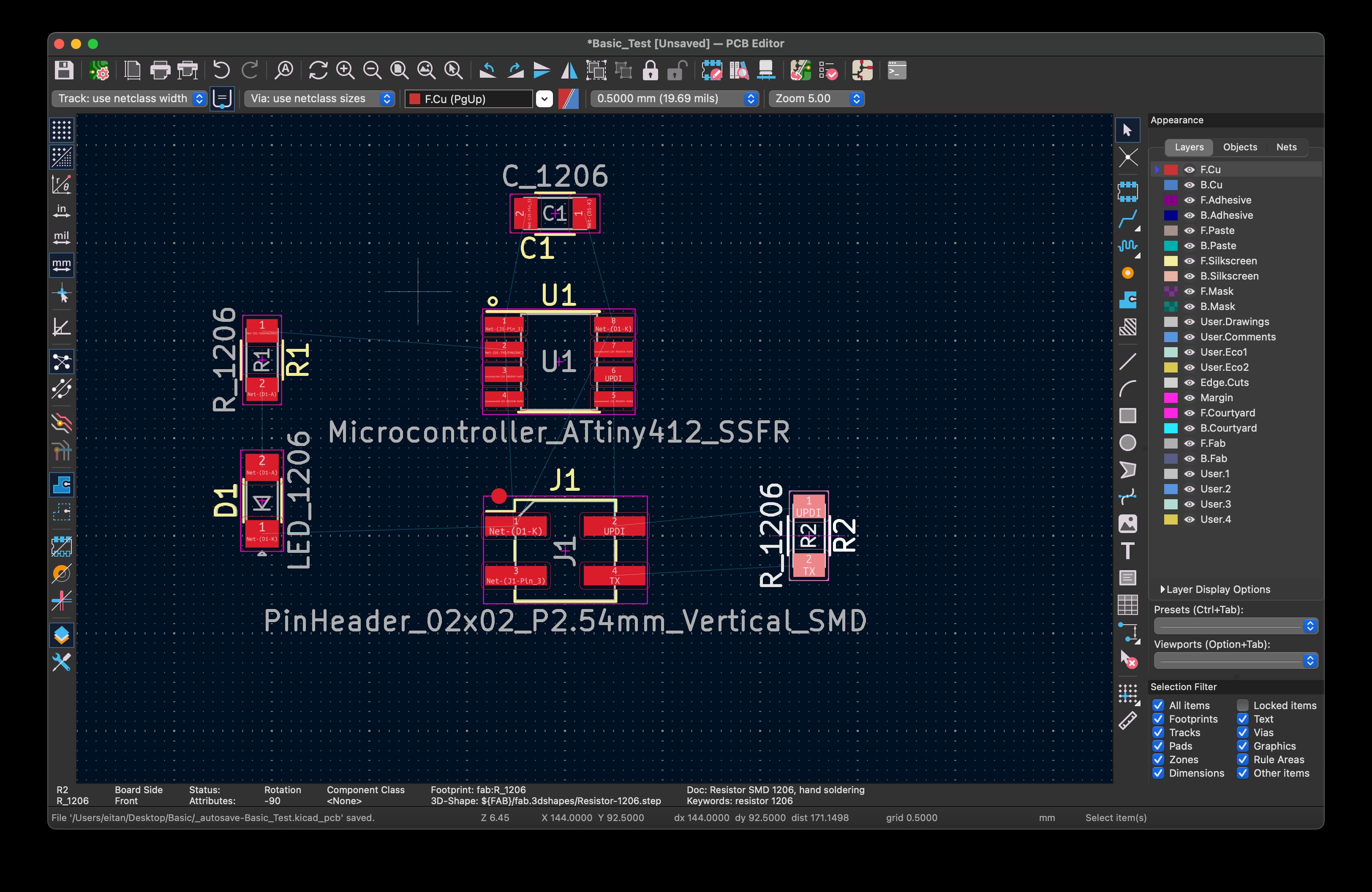
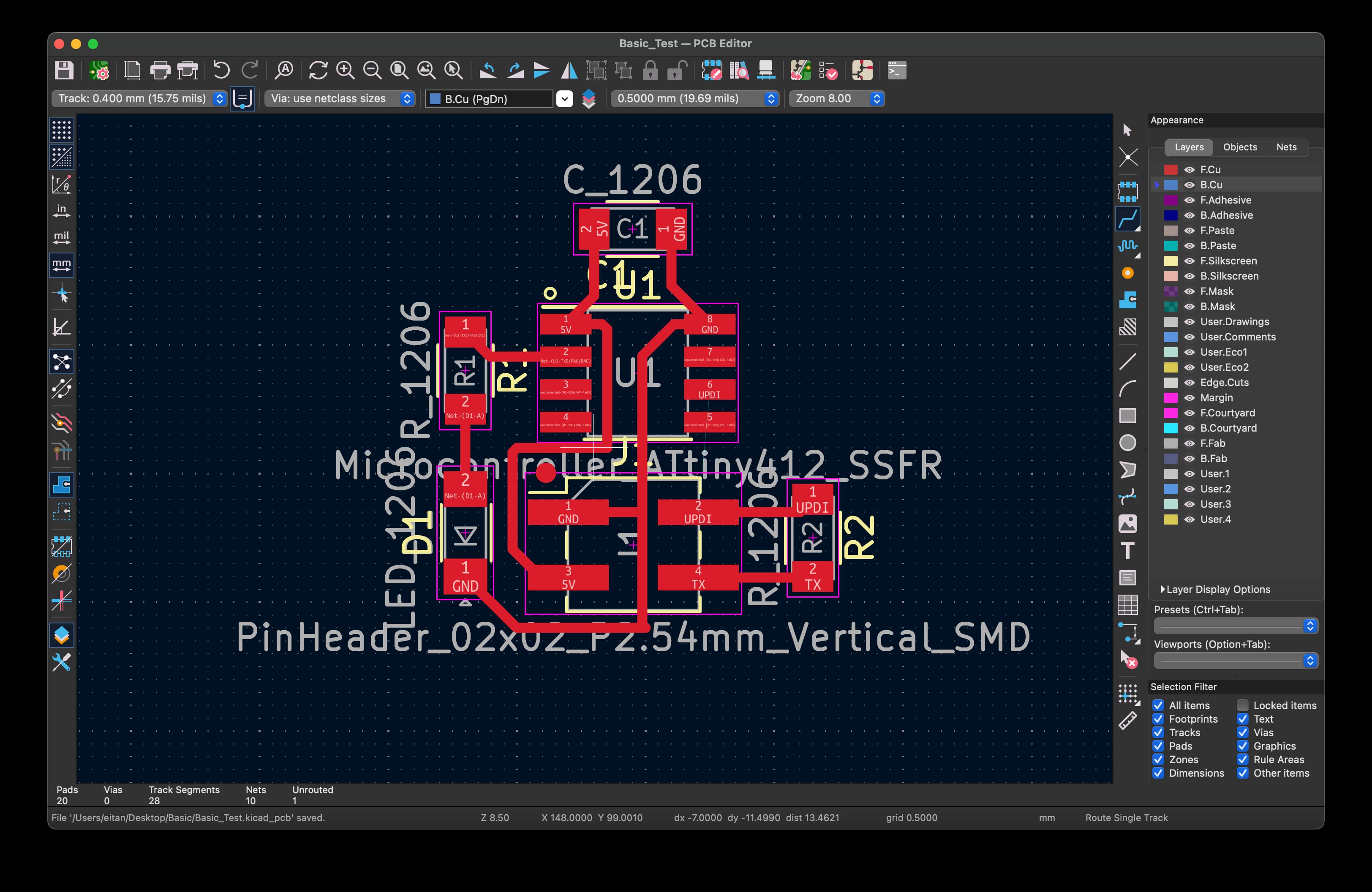
I will add more detailed documentation below soon, but this was the process of learning how to use KiCAD to organize relationships between components, then create the actual traces on the board. We also talked about design rules and how to simulate your circuits. Screenshots below, but more to come: