# Week 12
## Networking and Communications
### Group Assignment
> Send a message between two projects
I teamed up with Adin to use one of my controller board with up and down capacitive touch arrows to send a message to his board that controls a servo motor board.
We soldered a ground wire to my board so that both boards would have the same ground.
| 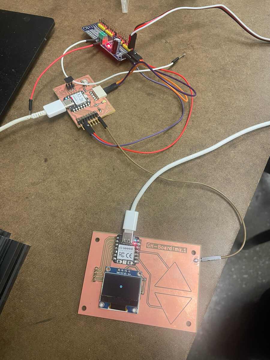 |
|:---------:|
| *The two seperate boards with the same ground* |
Then we needed to set up two pins on his board to be inputs. After we made sure that was working.
We spent a lot of time debugging different things until we realized that the USB-C that we use to plug in the wall didn't work.
Here is the code for my board (the one that SENDS the message):
```cpp
#define PIN_RED 17
#define PIN_GREEN 16
#define PIN_BLUE 25
#define N_TOUCH 2
#define THRESHOLD 30
int touch_pins[N_TOUCH] = {3, 2};
int touch_values[N_TOUCH] = {0, 0};
//Define Pin Outputs
const int PinUpOutput = D2; // Positive Sweep
const int PinDownOutput = D3; // Negative Sweep
bool pin_touched_now[N_TOUCH] = {false, false};
bool pin_touched_past[N_TOUCH] = {false, false};
void update_touch() {
int t;
int t_max = 200;
int p;
for (int i = 0; i < N_TOUCH; i++) {
p = touch_pins[i];
// set to low
pinMode(p, OUTPUT);
digitalWriteFast(p, LOW);
// settle
delayMicroseconds(25);
// enable pull-up
pinMode(p, INPUT_PULLUP);
// measure time to rise
t = 0;
while (!digitalReadFast(p) && t < t_max) {
t++;
}
touch_values[i] = t;
// update state
pin_touched_past[i] = pin_touched_now[i];
pin_touched_now[i] = touch_values[i] > THRESHOLD;
}
}
void print_touch() {
char print_buffer[30];
for (int i=0; i < N_TOUCH; i++) {
sprintf(print_buffer, "%4d ", touch_values[i]);
Serial.print(print_buffer);
}
Serial.println("");
}
void setup() {
// initialize Serial port
Serial.begin(0);
pinMode(PinUpOutput, OUTPUT);
pinMode(PinDownOutput, OUTPUT);
}
void loop() {
// update the touch sensors
update_touch();
// example pressed button
if (pin_touched_now[0]) {
// button 0 was just pressed, do something
digitalWrite(PinUpOutput, HIGH);
} else{
digitalWrite(PinUpOutput, LOW);
}
// example pressed button
if (pin_touched_now[1]) {
// button 1 was just pressed, do something
digitalWrite(PinDownOutput, HIGH);
} else{
digitalWrite(PinDownOutput, LOW);
}
// print values to Serial, for debugging
print_touch();
// slow down the loop to not print too fast (optional)
delay(50);
}
```
Here is the code for Adin's board (the one that RECEIVES the message):
```cpp
#include Wire.h // Add brackets around Wire.h
#include Adafruit_PWMServoDriver.h // Add brackets around Ada...Driver.h
Adafruit_PWMServoDriver pwm = Adafruit_PWMServoDriver(0x40);
// Servo pulse limits for DS3218MG
#define SERVO_MIN 150 // approx 0.5 ms
#define SERVO_MAX 600 // approx 2.5 ms
// Pin Input Setup
const int PinPosInput = D2; // Positive Sweep
const int PinNegInput = D3; // Negative Sweep
// Choose which PCA9685 pin your servo is on:
int servoChannel = 0; // LEFT MOST PIN on your board
// Convert angle → PWM pulse
int angleToPulse(float angleDeg) {
angleDeg = constrain(angleDeg, 0, 270);
float pulse = SERVO_MIN + (angleDeg / 270.0f) * (SERVO_MAX - SERVO_MIN);
return (int)pulse;
}
void setup() {
// Initialize Serial communication
Serial.begin(9600);
while (!Serial) {
; // Wait for Serial to initialize (optional on some boards)
}
Serial.println("System initialized. Waiting for switch input...");
Wire.begin();
pwm.begin();
pwm.setPWMFreq(50); // Standard servo frequency
delay(10);
pinMode(PinPosInput, INPUT_PULLUP);
pinMode(PinNegInput, INPUT_PULLUP);
}
void loop() {
// High means Positive
digitalRead(PinPosInput);
// High means Positive
digitalRead(PinNegInput);
// Send serial output
Serial.print("PinPosInput: ");
Serial.print(digitalRead(PinPosInput));
Serial.print("PinNegInput: ");
Serial.println(digitalRead(PinNegInput));
delay(50); // Small delay to make serial output readable
}
```
Here is the video of the two boards communicating:
## Individual Assignment
> design, build, and connect wired or wireless node(s) with network or bus addresses and local input &/or output device(s)
### I2C
I used I2C to communicate with the [DFPlayer](https://www.dfrobot.com/product-1121.html) for my final project. Please see the final project page.
### Serial Communications
From reading the [Serial Communications article on Wikipedia](https://en.wikipedia.org/wiki/Serial_communication), serial port communication is any type of communication that sends information serially, one bit at a time. USB also sends data in a serial stream. The [RS-232 Standard](https://en.wikipedia.org/wiki/RS-232) is what common serial ports use, and it was interesting to read about how the ports that many computers, screens and other devices used to commonly had work via this protocol.
I looked at an article about how to [read from and write to a serial port.](https://developer.chrome.com/docs/capabilities/serial)
#### Serial.available()
This function caused me some trouble because the term "available" is misleading. It is not true when the serial connection is established or listening. It is only true when there is communication occuring on the serial line! The [arduino Serial.available() documentation](https://docs.arduino.cc/language-reference/en/functions/communication/serial/available/) implies it with the comment "reply only when you receive data," but it is not said explicitly.
To first understand how the serial port works when interfacing with our microcontrollers, I wrote this script.
## Attachments
[attachment-1.ext](files/attachment-1.ext)
## Acknowledgments
Adin for his cool project and as a peer programmer for the group assignment.