# Week 3
## Overview of Embedded Architectures
### Group Project Portion
> Demonstrate and compare the toolchains and development workflows for available embedded architectures
I met in a group to discuss these topics. I started a new page on the architecture website titled [Week 2](https://fab.cba.mit.edu/classes/863.25/Architecture/week-2.html), which students in our section added to using git.
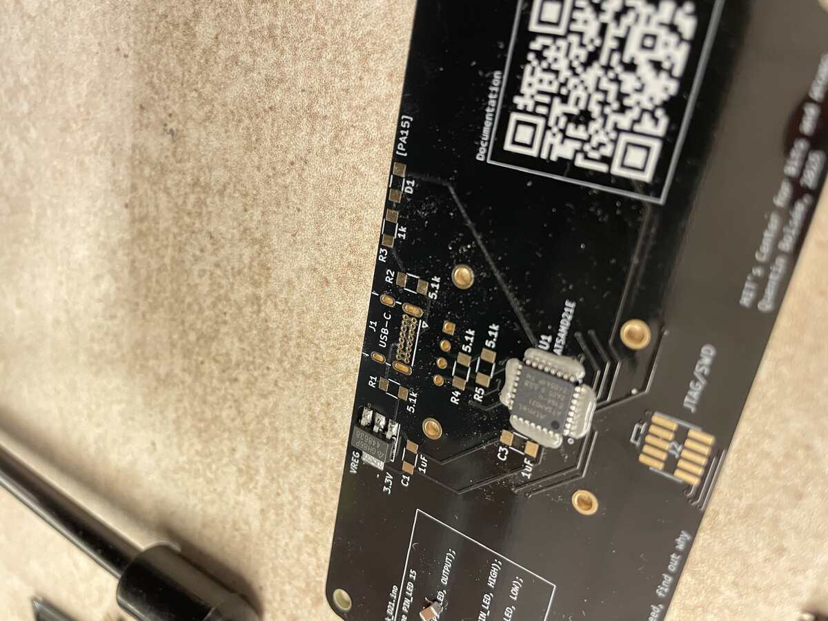
There are two types of boards available with Quentin Bolsee's QPad Kit.
The main difference between them is the two microprocessors they support: the RP2040 in the XIAO format and the ATSAMD21E. The XIAO kit requires less soldering (just the microprocessor, screen and two resistors for the screen), while the SAMD chip requires more external circuits to run (like a powersource, led, capacitors, resistors), and therefore more soldering!
The XIAO can support micropython, which is great if you like coding in python, though you need to be careful since it has less guardrails than the C-based code it also supports.
The SAMD kit comes in two versions, one with a USB C and another with a USB micro because of sourcing issues. Funily enough, one of the hardest parts of assembling the kit is these connectors. To me it seems that USB micro is harder because at least the USB C connections are not blocked by the sleeve of the connector itself, but I did USB C and not micro.
The programming environment for both using C is in the Arduino IDE.
### Individual Project Portion
> browse through the data sheet for your microcontroller
[Here is the parts list](http://inventory.fabcloud.io/?purpose=Embedded%20Programming) of all the available microcontrolers for this week.
I looked at a few of the data sheets and tried to highlight which boards are the most important.
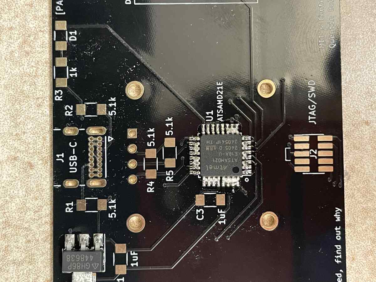
### ATSAMD21E
Reading [the ATSAMD21E manual](http://academy.cba.mit.edu/classes/embedded_programming/D21E/Atmel-42181-SAM-D21_Datasheet.pdf), I saw this diagram that explains what all the letters and numbers mean in the name of the device:
| 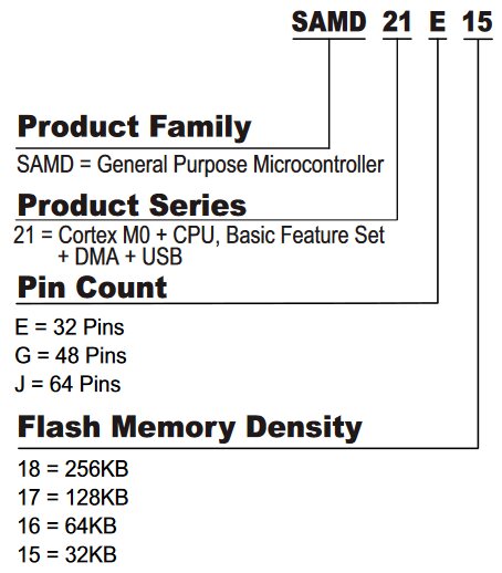 |
|:---------:|
| *from datasheet manual* |
Here is the key data:
| cost | pin count | flash memory |
|:---------:|:---------:|:---------:|
| *$ 3.66* | *32* | *32 kb* |
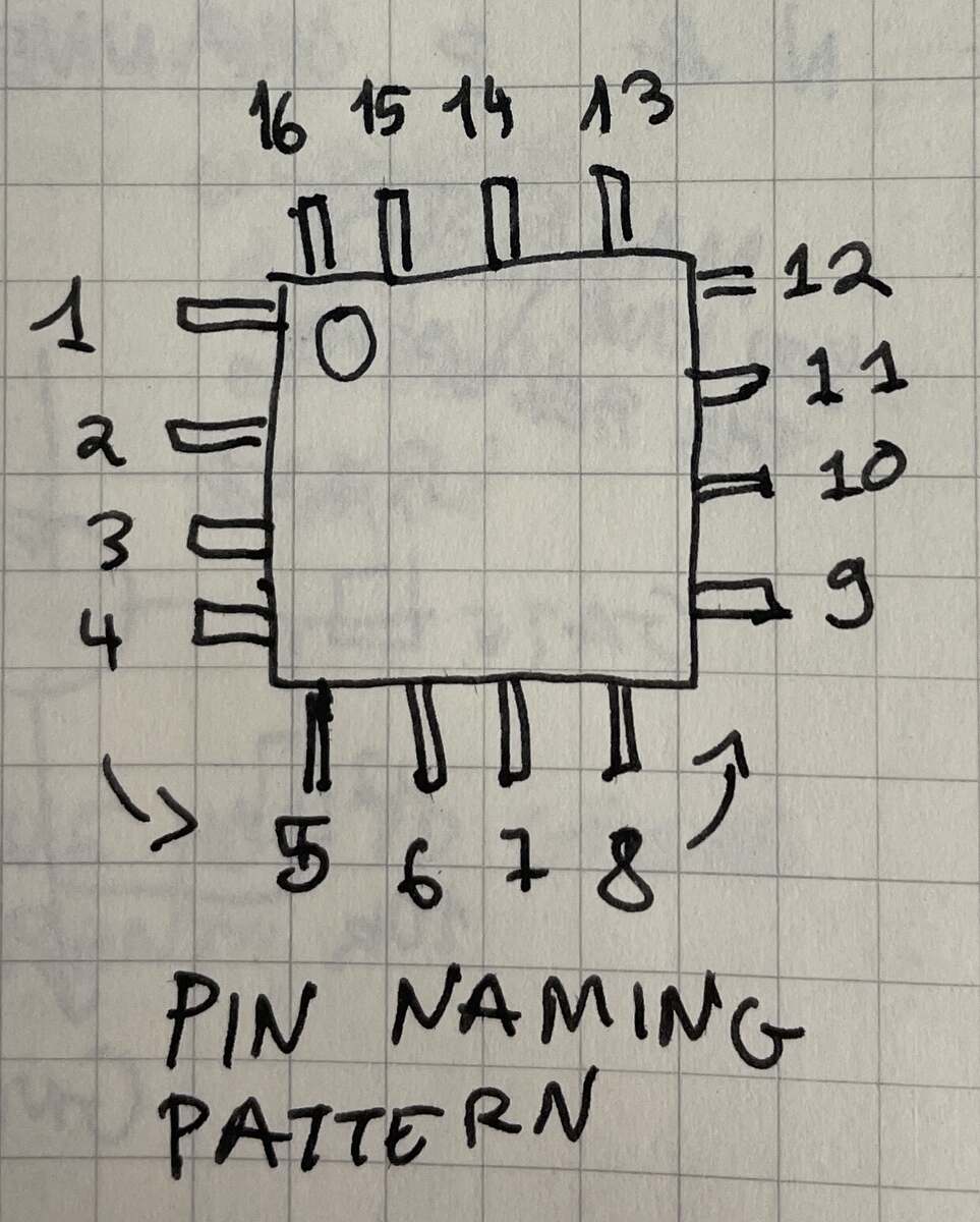
The convention for numbering the pins on a chip is counterclockwise from where the dot on it is located:
### ESP32
Choose this board if you need "Ultra-Low Power" efficiency. It is meant for Internet-of-Things type of applications, so it can not waste energy when not in use, and is probably the best option if battery life is a priority. It is has wifi and bluetooth.
Here is the key data:
| cost (USD) | pin count | flash memory (KB) |
|:---------:|:---------:|:---------:|
| *32* | *32* | *32* |
## Soldering the Hardware
### Soldering Demo
Some key takeaways from the demo:
- Use gloves with paste, use ventalation for flux fumes (lead isn't the issue in this case)
- Spools with Green Solder are **Lead Free**, Spools with White Solder have **Lead**
- Soldering Iron Temp should be **720 - 800 F / 270 - 330 C**
| 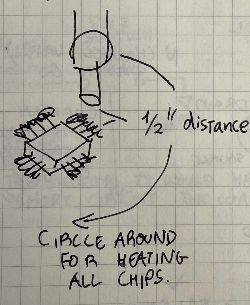 |
|:---------:|
| *Soldering a chip with paste and the heatgun* |
### Soldering the ATSAMD21E with USB C
The soldering tutorial showed how to use solder paste and a heat gun to solder a the tiny pins on the ATSAMD21E chip.
|  |  |  |
|:---------:|:---------:|:---------:|
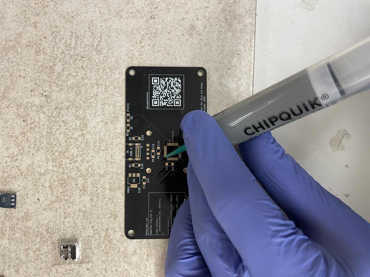
| *Apply Solder Paste* | *Place Chip* | *Use Heatgun to Transform Paste* |
I then assembled all the parts of the kit together and tried to give it a shot myself:
|  |
|:---------:|
| *Using tweezers to place components when paste is hot* |
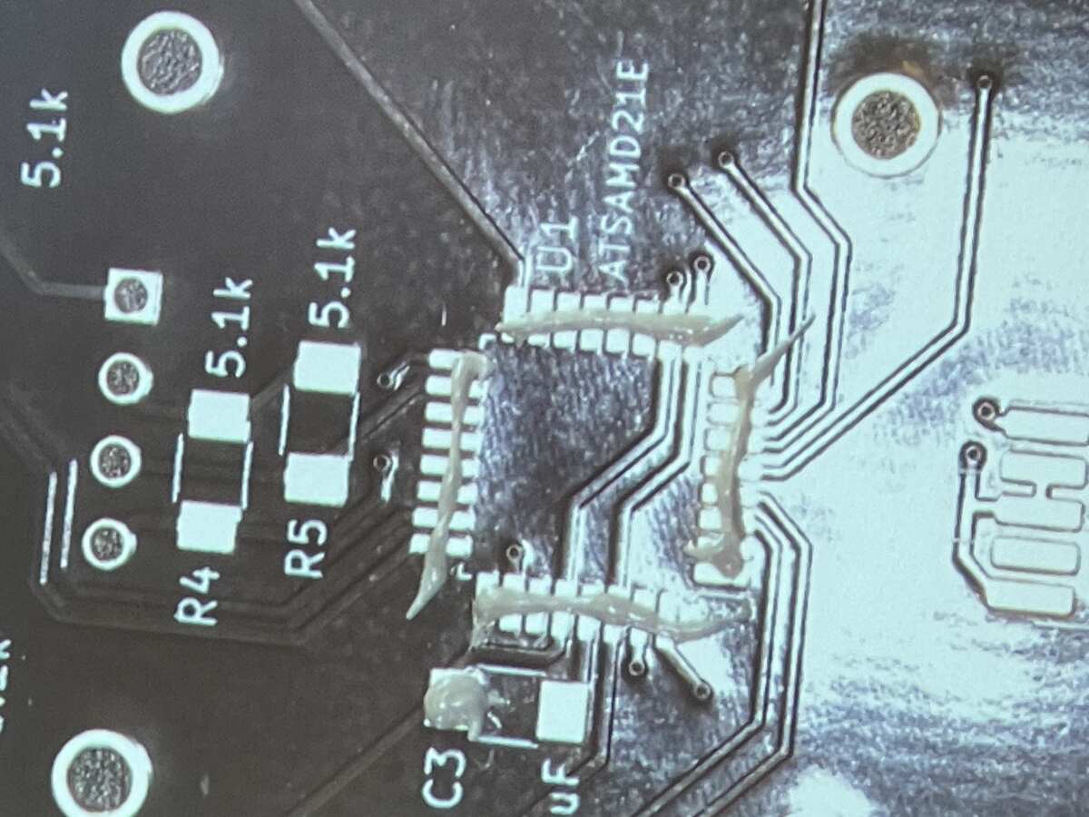
|  |  |  |
|:---------:|:---------:|:---------:|
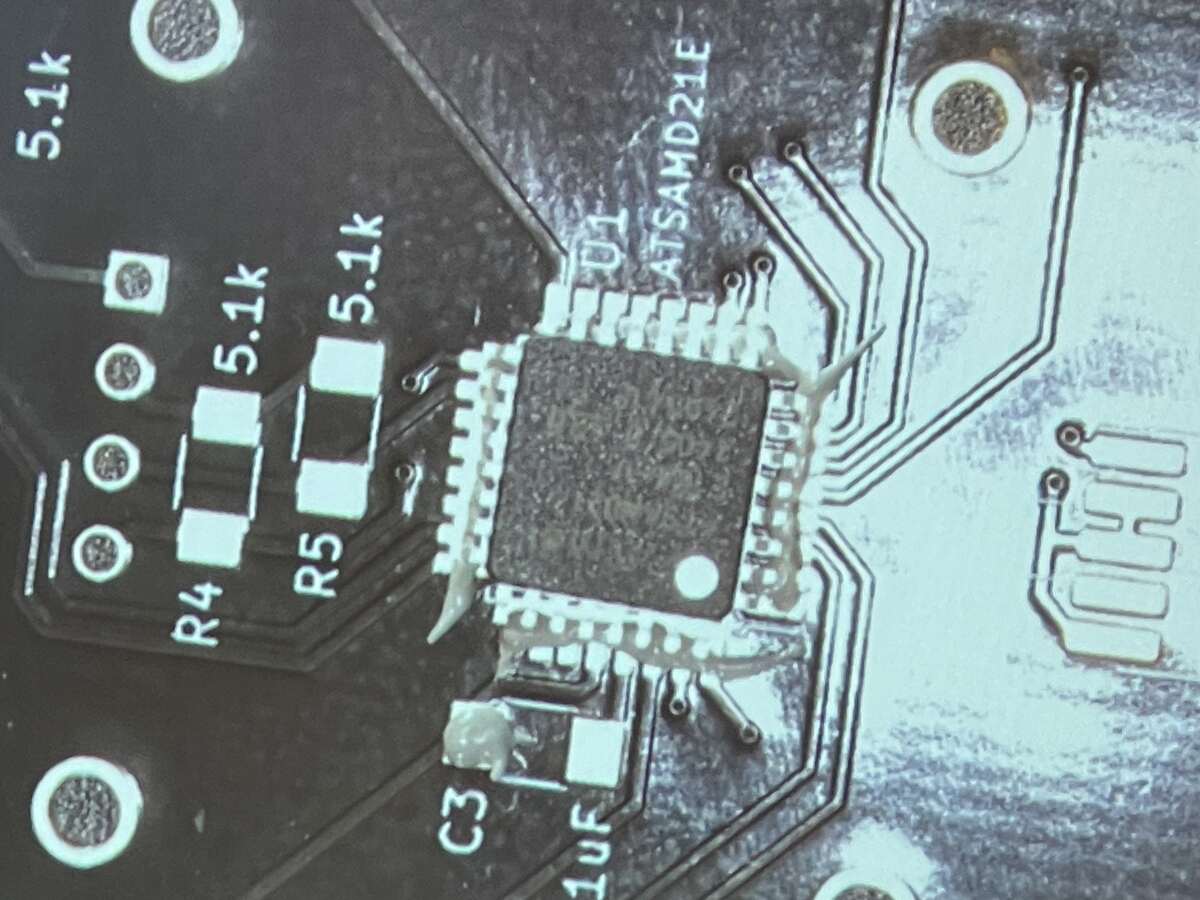
| *Applying Paste* | *I Place The Chip. Here there is too much paste* | *I Use Heatgun and Get Lots of Short Circuits* |
It was really cool to see how the chip placed itself well on all the contacts with this process.
Notice how there is way too much paste, which resulted in a lot of short circuits.
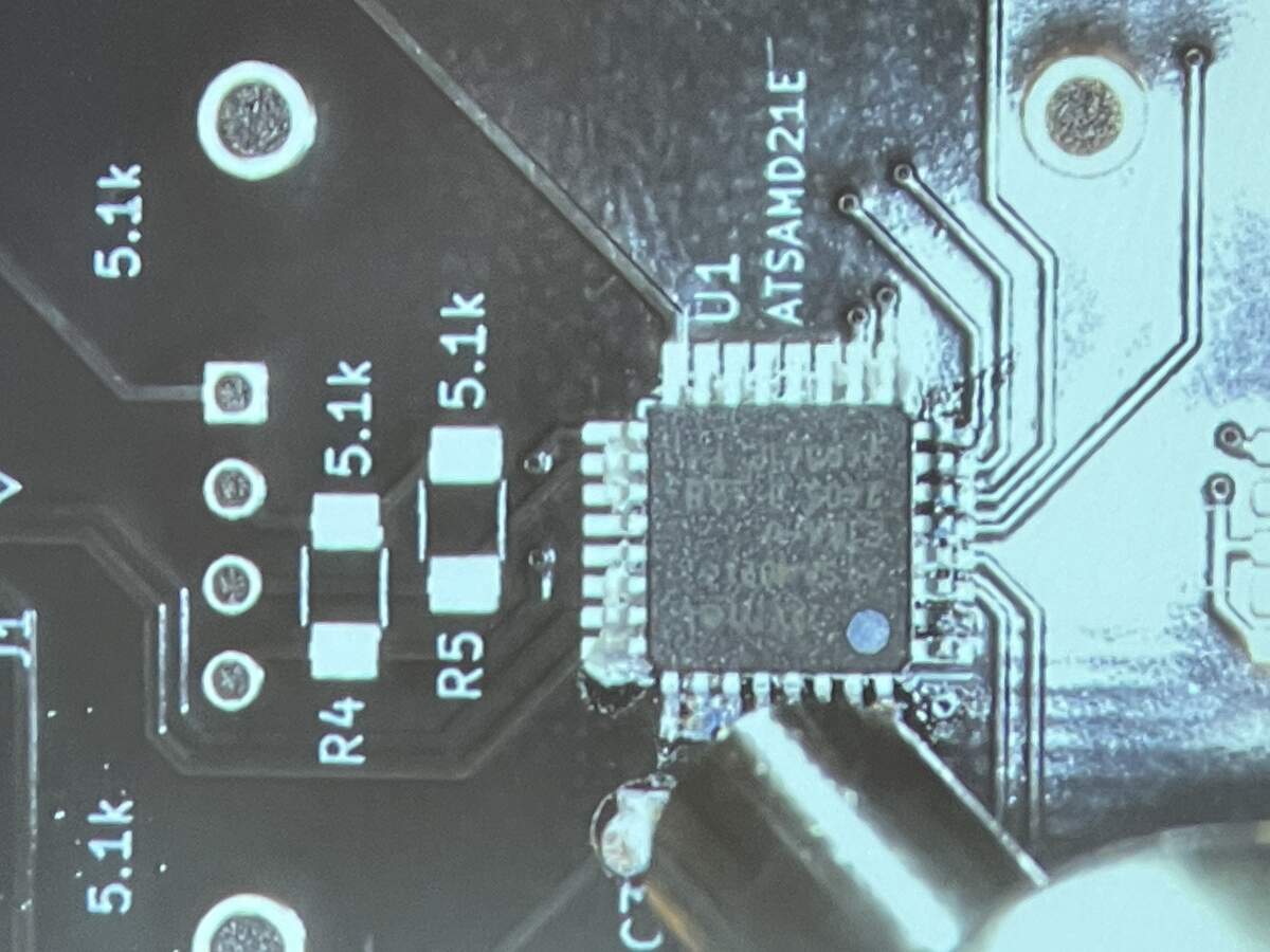
Thankfully this isn't very hard to fix, with copper mesh I can absorb a lot of the shorts.
Tips for getting copper mesh to absorb solder:
- Add more solder to the copper mesh which will actually absorb the solder underneath!
- Add flux using a flux pen to help it flow into the copper
I had to debug a lot of contact problems. First there might have been a bad connection at the USB-C connector. There also was an almost imperceptible connection between two of the pins. The most egregious problem was also my first solder with the soldering paste. I had applied so much soldering paste on the power converter component that it was making a contact underneath the component.
| 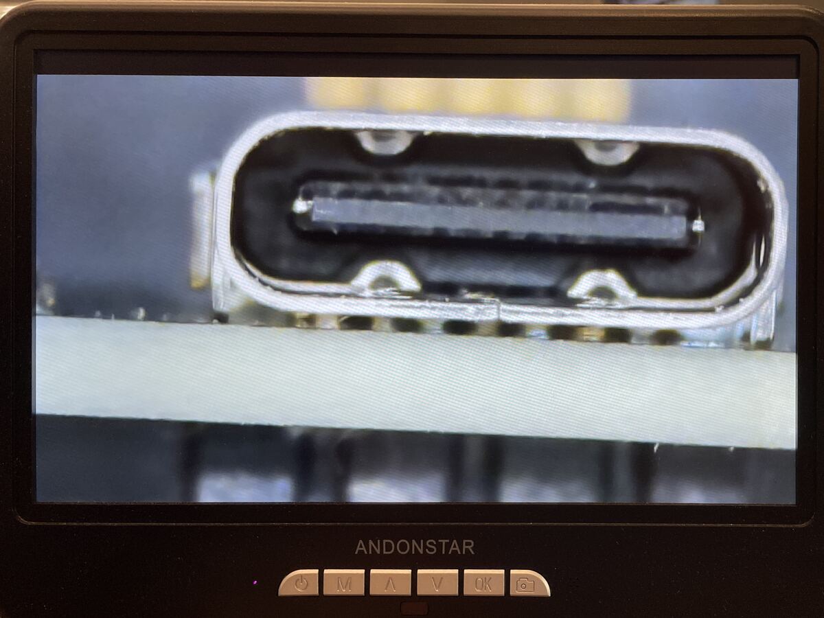 | 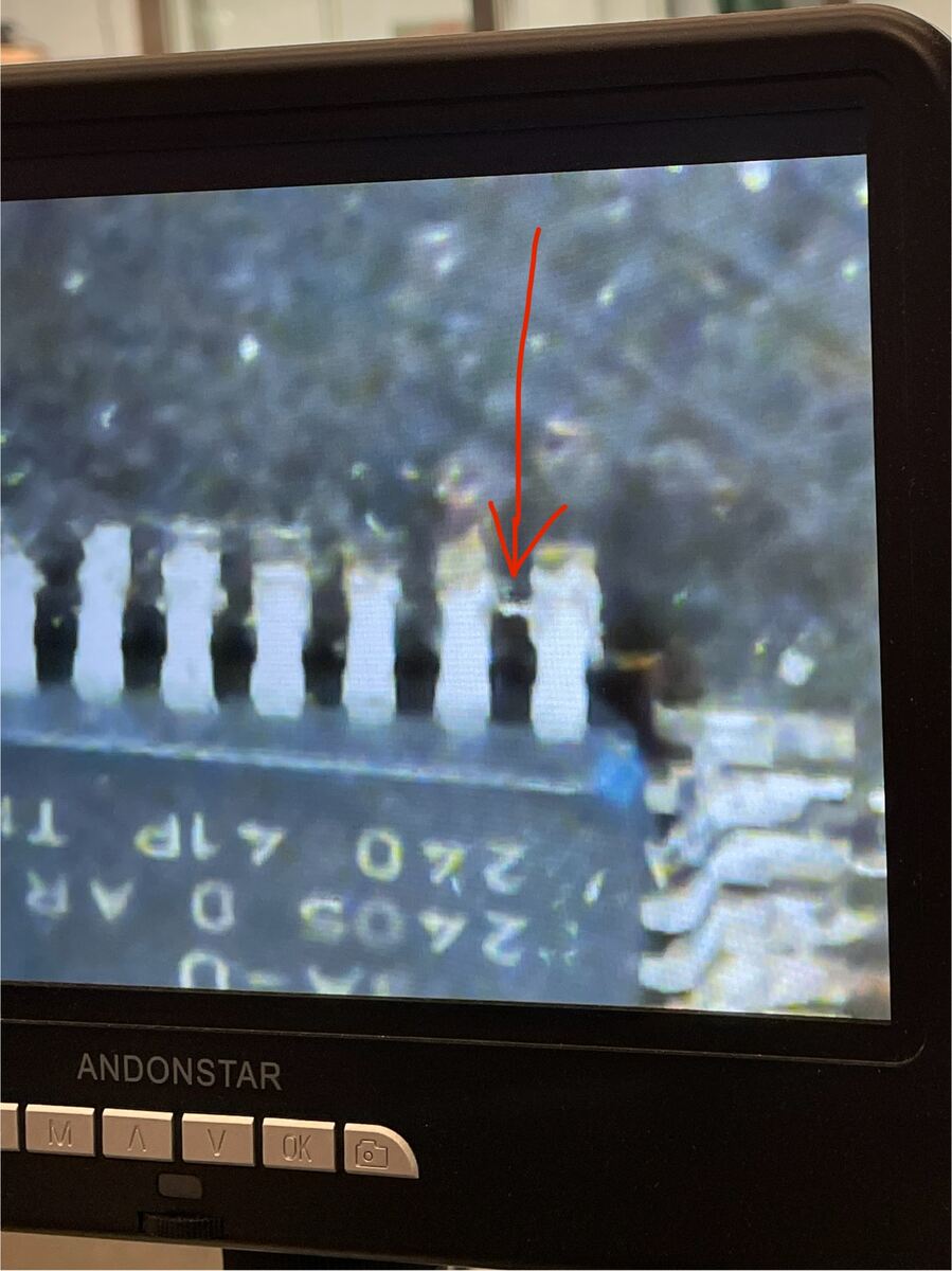 | 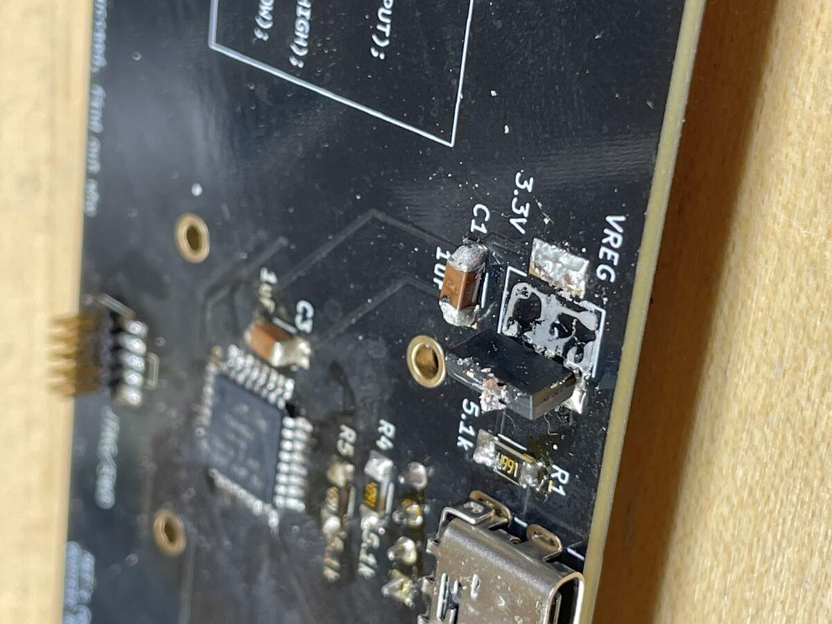 |
|:---------:|:---------:|:---------:|
| *Inspecting the USB-C connection with a microscope* | *A super small connection issue that can be seen only on the microscope* | *Too much paste left unheated under the power converter created a short* |
After a lot of debugging the hardware, I got a working board!
| 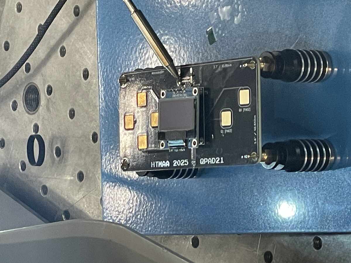 |
|:---------:|
| *A Handy stand for holding and soldering boards* |
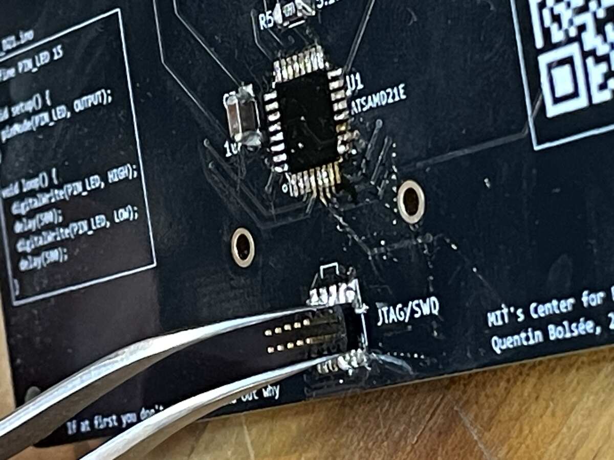
We flashed the SAMD chip using a bootloader with Quentin's help:
| 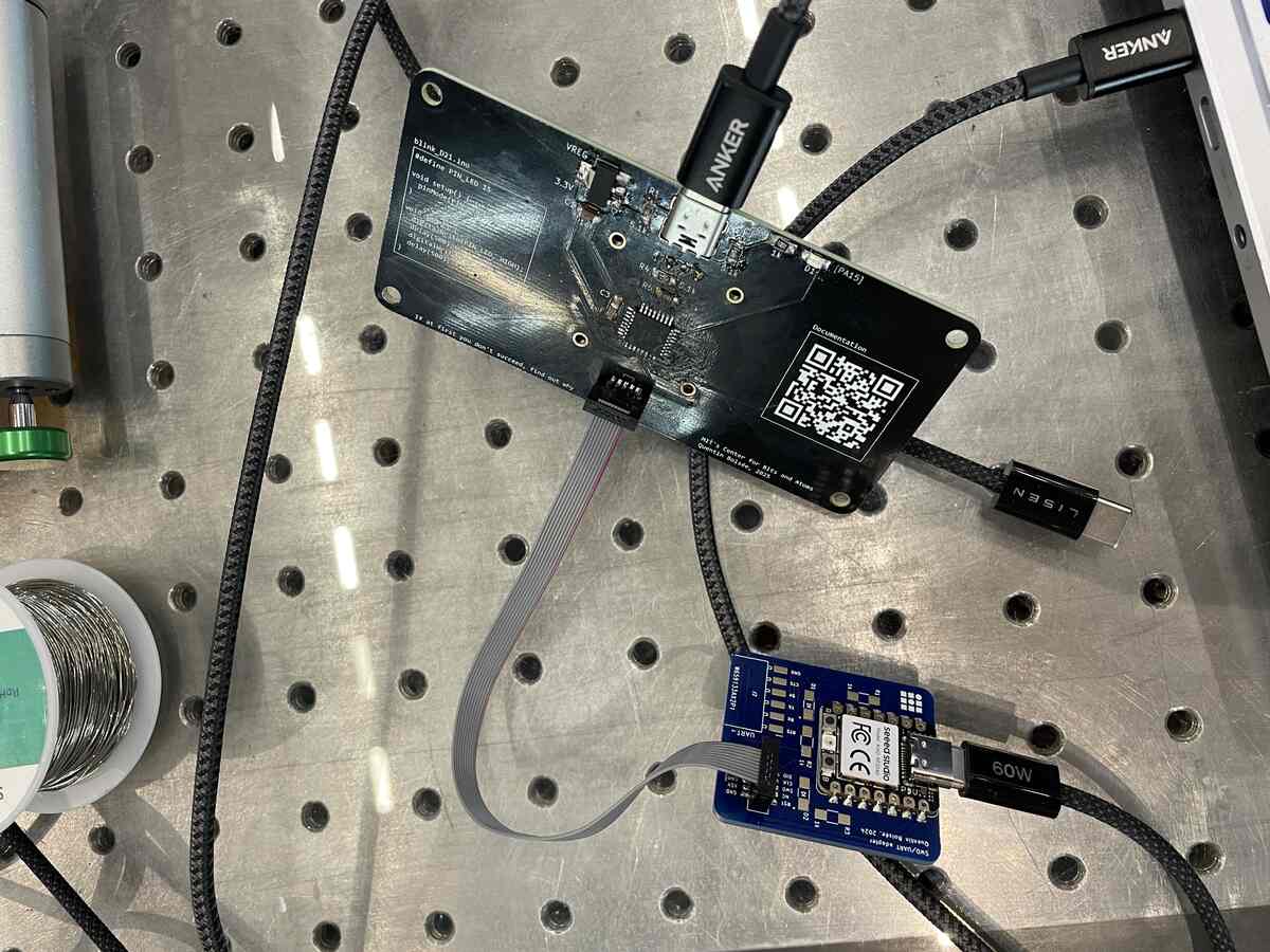 |
|:---------:|
| *Using a bootloader to format the SAMD21e* |
Success!
| 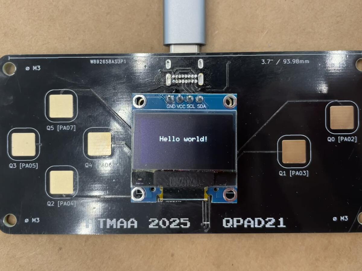 |
|:---------:|
| *Hello World on the SAMD21e QPAD* |
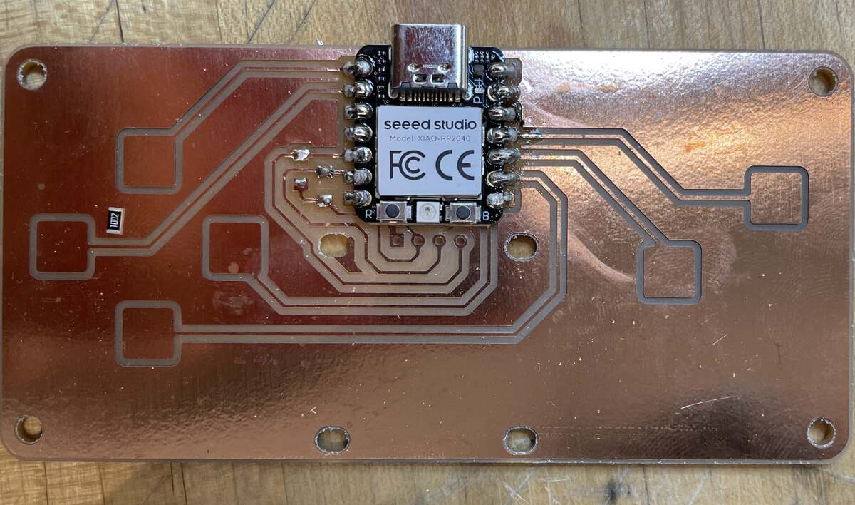
### Soldering the XIAO RP2040
Once I did the harder kit, I wanted to also solder the XIAO to have the RP2040 to test with. I found it to be much easier.
| 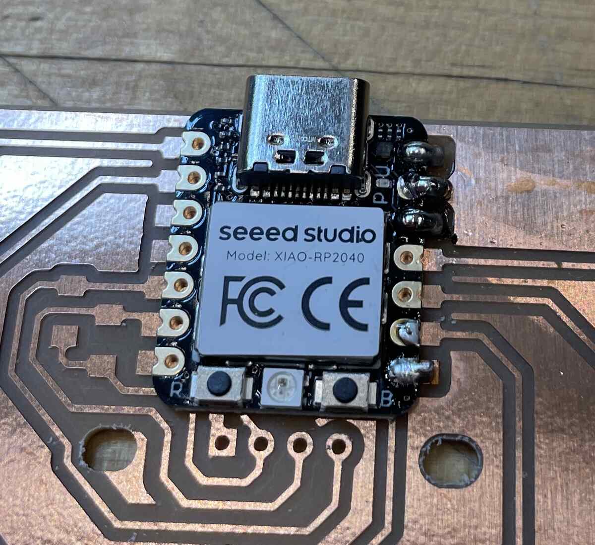 |  |
|:---------:|:---------:|
| *Pinning the XIAO down with one solder* | *Tinning all the contacts for the resistors and soldering the chip* |
The board also comes with a screen holder with m3 screws.
| 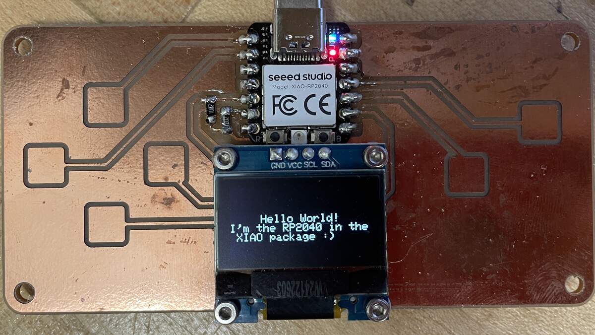 |
|:---------:|
| *Hello World RP2040* |
Key things I learned:
- Use flux or add solder to get solder to flow
- Be extremely sparing with soldering paste
## Coding the Microcontrollers
> write and test a program for an embedded system using a microcontroller to interact (with local input &/or output devices) and communicate (with remote wired or wireless connections).
### Getting started with the rp2040 and Arduino IDE
1. Download the [Arduino IDE](https://www.arduino.cc/en/software/)
2. Open Arduino IDE and go to File -> Preferences (the next few steps are from [earlephilhower/Arduino Pi](https://github.com/earlephilhower/arduino-pico?tab=readme-ov-file#installation))
3. Enter the following URL in "Additional Boards Manager URLs":
`https://github.com/earlephilhower/arduino-pico/releases/download/global/package_rp2040_index.json`
| 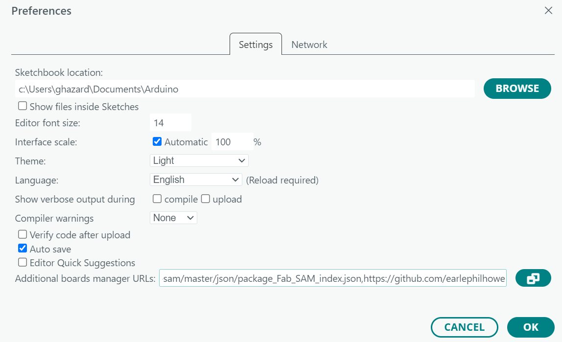 |
|:---------:|
| *To use multiple boards, click on the two squares icon to the right of the text box or [separate the different url with a comma](https://github.com/arduino/Arduino/issues/3092).* |
If you want to also install support for the SAMD21e, add:
`https://raw.githubusercontent.com/qbolsee/ArduinoCore-fab-sam/master/json/package_Fab_SAM_index.json`
4. Find which port your XIAO is plugged into by pluging & unplugging and seeing which port shows up and is gone.
5. In the Select Other Board and Port dialog box, look up and select `Seeed XIAO RP2040` in the boards.
6. You will be prompted to install the `Raspberry Pi Pico/RP2040/RP2350` package in the sidebar. Click download.
7. Install any dependencies, notably the Adafruit GFX and Adafruit_SSD1306 Libraries from which [Quentin's arduino sample code](https://gitlab.cba.mit.edu/quentinbolsee/qpad-xiao/-/tree/main/code/Arduino?ref_type=heads) depends on.
8. Write your code in the IDE. [Here is starting code for the RP2040](https://gitlab.cba.mit.edu/quentinbolsee/qpad-xiao/-/tree/main/code/Arduino?ref_type=heads)
9. Press the Arrow top right to write the code to your board!
### Coding the SAMD21e
Follow [Quentin Bolsee's Arduino SAM Tutorial](https://gitlab.cba.mit.edu/quentinbolsee/Arduino-SAM-tutorial/) to get set up.
Make sure to install the `Adafruit FreeTouch Library` dependency.
First I wrote a simple program that combines the sample code. It displays the information from the touch controls on the display, and communicates the values to the computer.
| 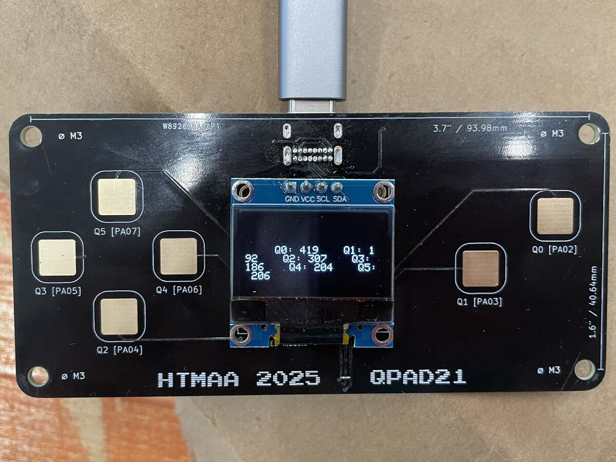 | 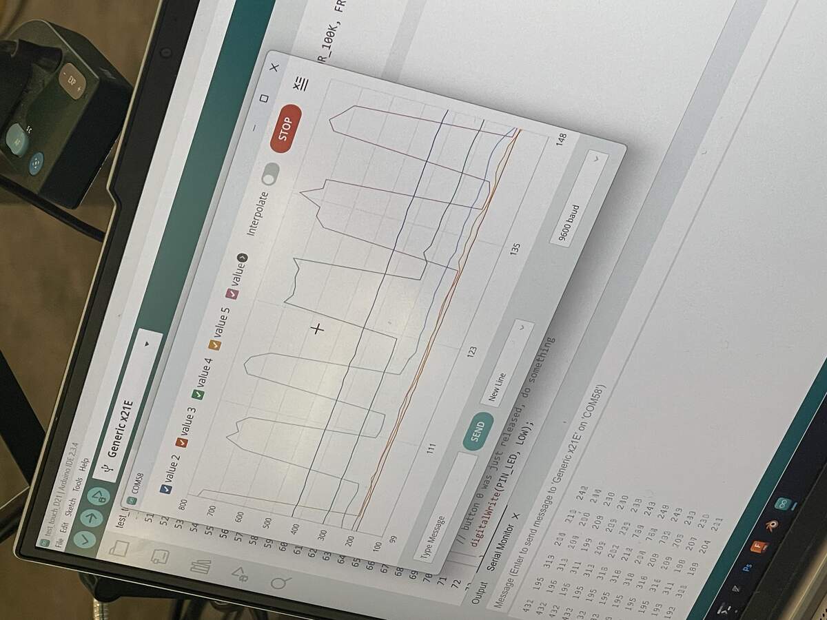 |
|:---------:|:---------:|
| *Displaying the values of the capacitive touch sensors on the screen* | *Observing the values on the computer via a wired connection* |
Here is a video that shows the system registering the inputs from the capacitive sensors on the screen:
Just to get a sense of what the device was capable of, I wanted to see if it could run Doom. I used AI to write the code for me.
[Here is the prompt I used.](https://claude.ai/share/5fc32c48-cca8-4809-a6e2-1e812f44a5b0)
Here's a bit more gameplay where I defeat an enemy:
I found this really exciting, but I wanted to understand better how the code worked to have more control over the components.
### Pixels on the Screen
Both of these Boards use a [B09JWN8K99 0.96 Inch OLED Module 12864](https://www.amazon.com/Self-Luminous-Display-Compatible-Arduino-Raspberry/dp/B09JWN8K99/?th=1).
It is **128 pixels** wide and **32 pixels** tall.
First I made a simple code that can draw any bit onto the screen. I referenced this [image2cpp tutorial](https://github.com/javl/image2cpp/blob/main/oled_example/oled_example.ino).
Using the `display.drawBitmap` command, I learned how to input a list of binary numbers and draw them on the screen:
``` .ino
// Storing a 8x8 smiley face,
// where each binary number represents a row of pixels 8 wide = 1 byte
const unsigned char PROGMEM smiley_8x8[] = {
0b00111100, // ⚪⚪⚫⚫⚫⚫⚪⚪ Row 0
0b01000010, // ⚪⚫⚪⚪⚪⚪⚫⚪ Row 1
0b10100101, // ⚫⚪⚫⚪⚪⚫⚪⚫ Row 2 (eyes)
0b10000001, // ⚫⚪⚪⚪⚪⚪⚪⚫ Row 3
0b10100101, // ⚫⚪⚫⚪⚪⚫⚪⚫ Row 4 (smile)
0b10011001, // ⚫⚪⚪⚫⚫⚪⚪⚫ Row 5 (smile)
0b01000010, // ⚪⚫⚪⚪⚪⚪⚫⚪ Row 6
0b00111100 // ⚪⚪⚫⚫⚫⚫⚪⚪ Row 7
};
// Later in code
// Draw the smiley face
display.drawBitmap(60, 28, smiley_8x8, 8, 8, SSD1306_WHITE);
```
| 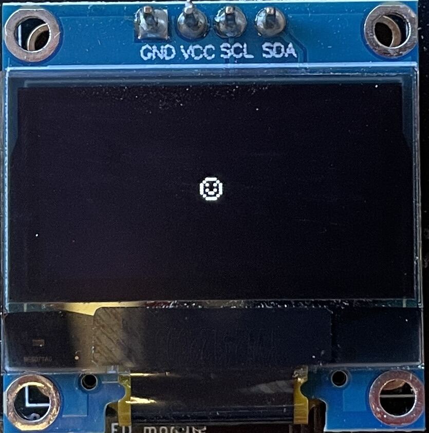 |
|:---------:|
| *Displaying the smiley on the screen* |
You can find the full example code in attachements.
I then used the following workflow:
1. Generate a bit animation using [Piskel](https://www.piskelapp.com/)
2. Export the animation as a series of separate .png frames
2. Use [image2cpp](https://javl.github.io/image2cpp/) to turn them into arrays to store on the arduino.
3. Paste the code into the arduino IDE as needed.
> extra credit: try different languages &/or development environments
## Attachments
[Simple code to activate pixels on screen](files/251026-Simple-Screen-Pixels.ino)
[Doom-like Code](files/Doom-Like-No-Homescreen.ino)
## Acknowledgments
- Quentin for designing the boards and helping me debug.
- Anthony for running the soldering workshop and support in debugging.
- Alan for helping me debug and teaching me tricks on soldering.