# Week 6
## Electronics Production
### Group Assignment
> characterize the design rules for your in-house PCB production process
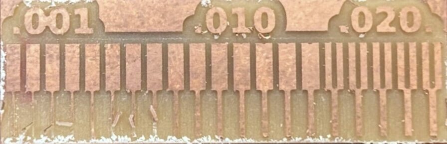
The ideal is to not have any traces that are below 0.02 of an inch.
From recitation last week, Quentin said to have 0.4 mm or 1/16th of an inch minimum, so I went with that for the board design last week.
As we can see from the test made by [Ayah Mahmoud](https://fab.cba.mit.edu/classes/863.25/people/AyahMahmoud/), the machine cannot create gaps between traces for anything below 0.02 inches. Note that it can still machine traces individually until about 0.01 inches of thickness.
|  |
|:---------:|
| *Closeup of precision test made by Ayah* |
> submit a PCB design to a board house
### Individual Assignment
> Make and test an embedded microcontroller system that you designed
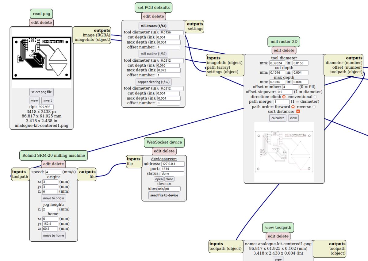
I used the Modela SRM-20 to mill my PCB. Gert kindly helped me get set up, and I followed the [archshops tutorial](https://archshops.mit.edu/modela.php) to use the machine which is comprehensive.
|  |  |
|:---------:|:---------:|
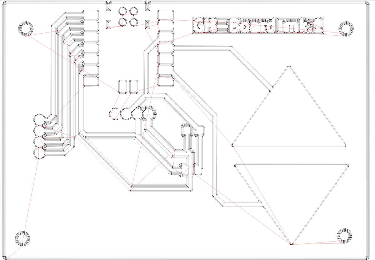
| *Setting up the trace cut file in mods* | *Inspecting the toolpath* |
|  |  |  |
|:---------:|:---------:|:---------:|
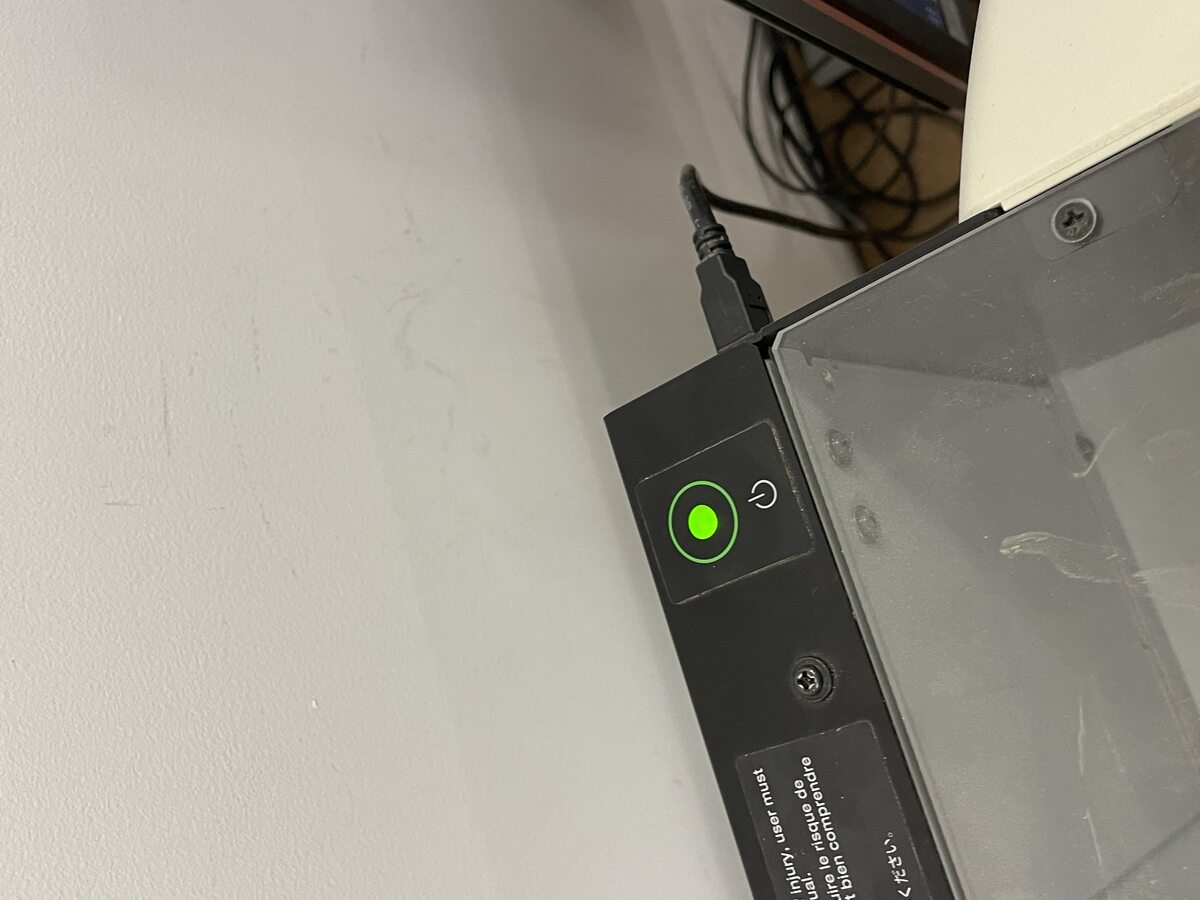
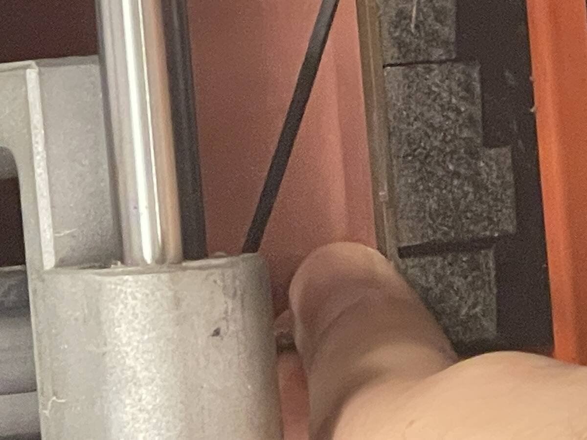
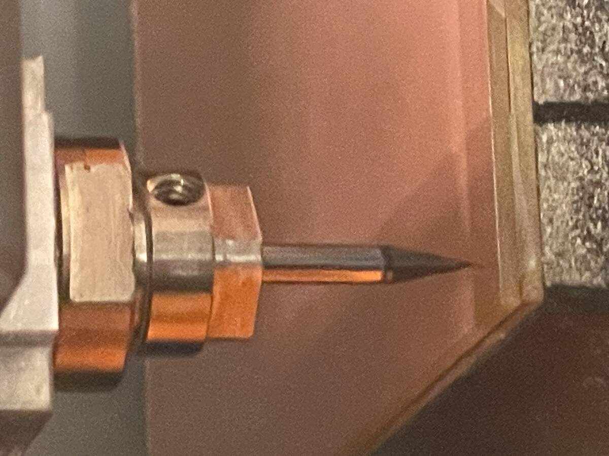
| *Turn the machine on and off by pressing this button if the door is opened when running a command, It will have a blinking light and not want to continue.* | *Press the bit gently down into the board and tighten the hex at the top to set it to the right height* | *This is what the bit should look like to start milling* |
|  |  |
|:---------:|:---------:|
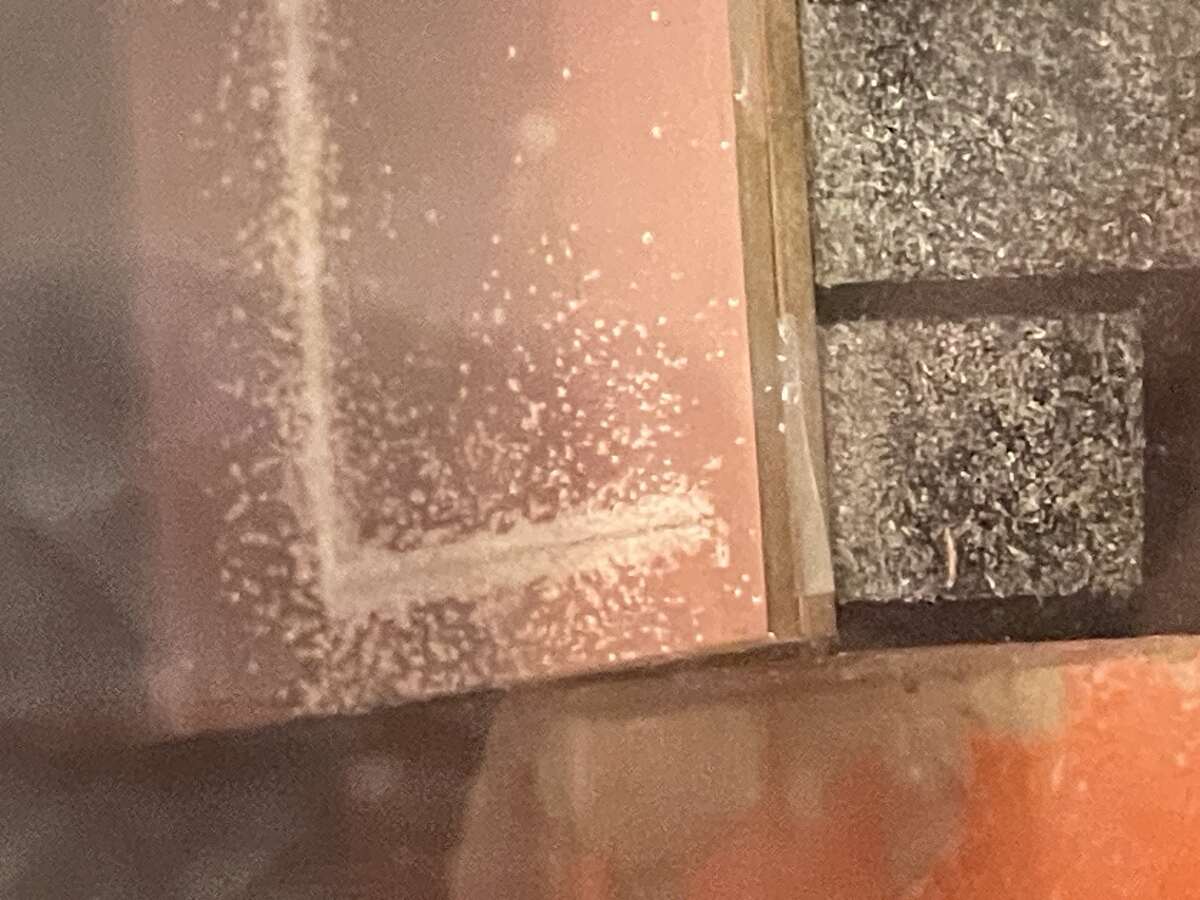
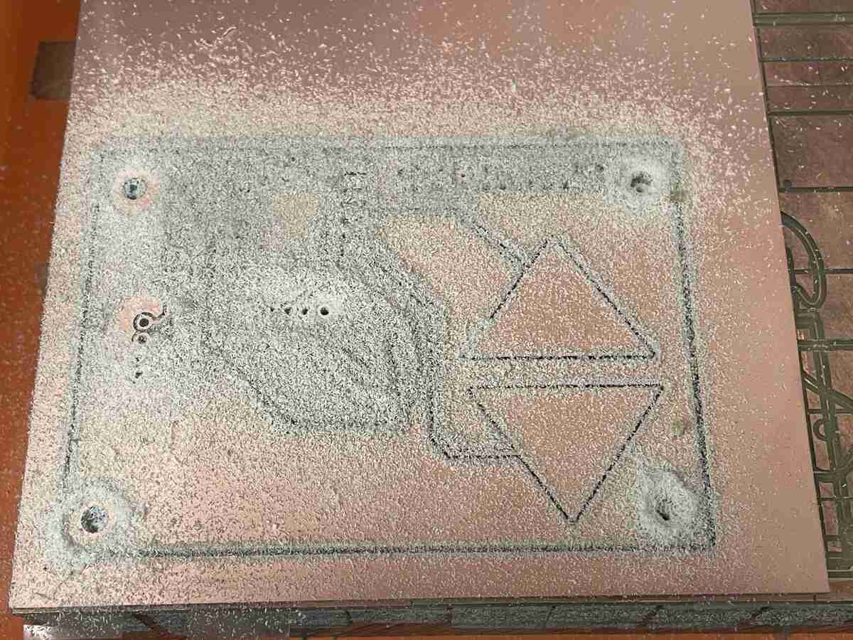
| *Right amount of "chipping" residue means things are running smoothly.* | *The completed board with the holes and outline cut.* |
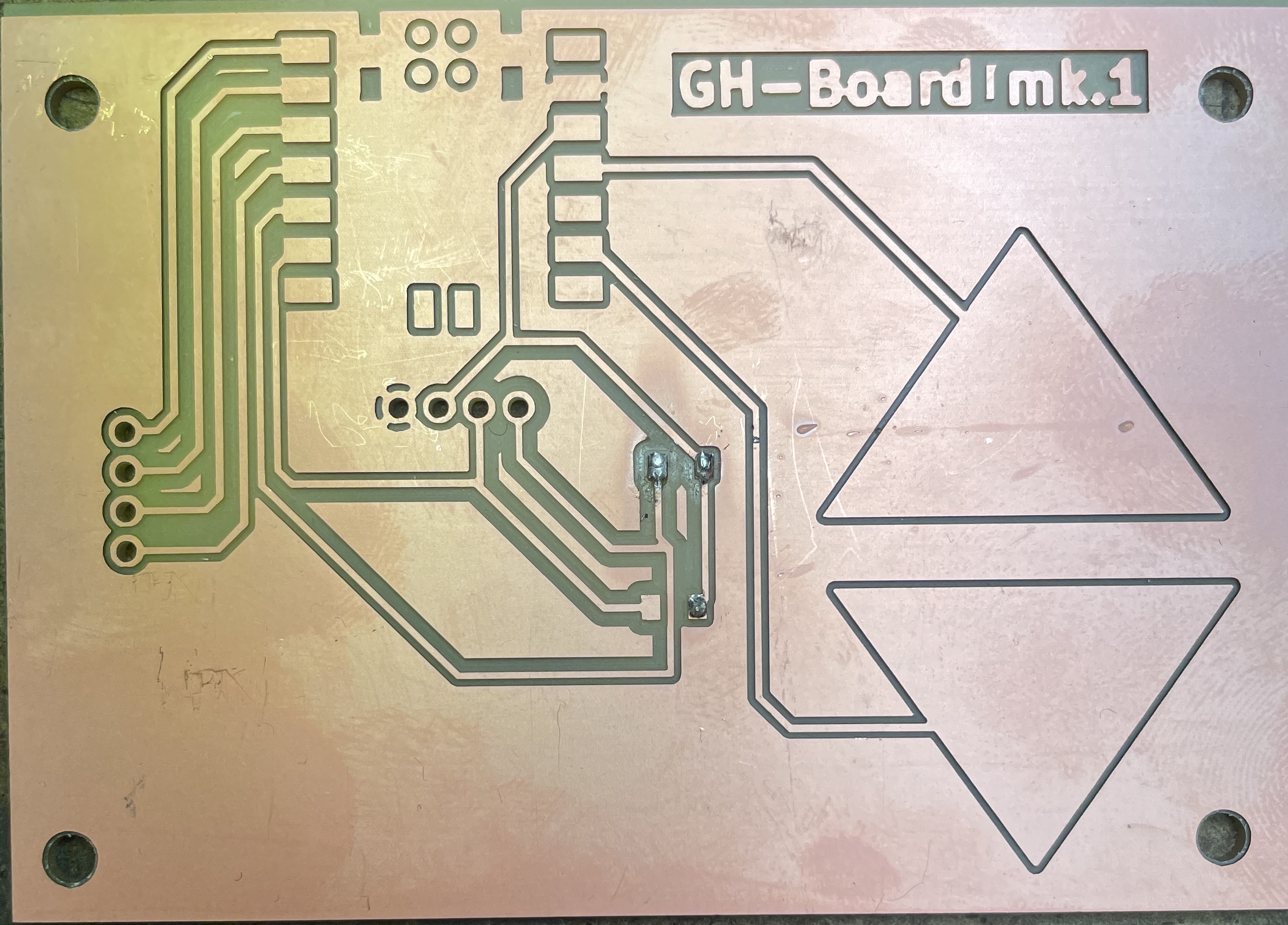
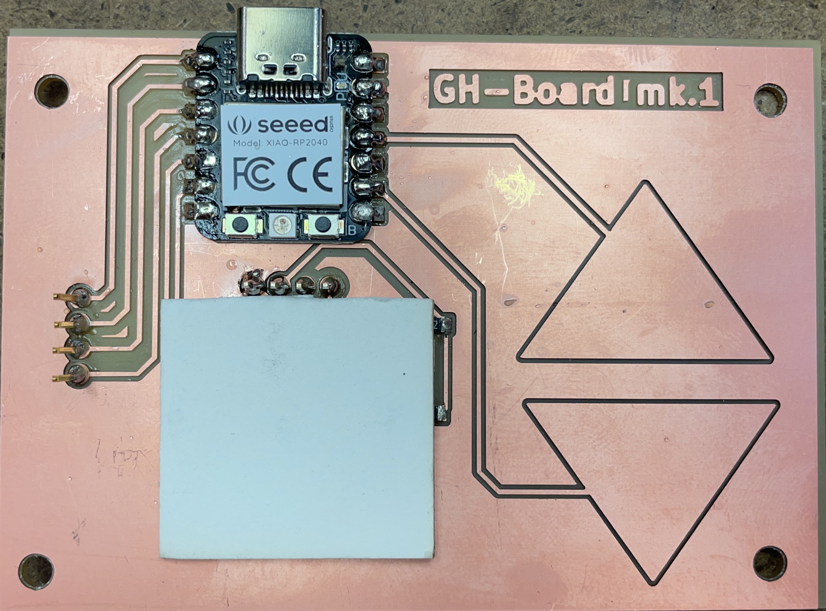
I found that the board did not need any scraping or finishing, but did that there was a bit of copper that needed to be removed between traces at the top right.
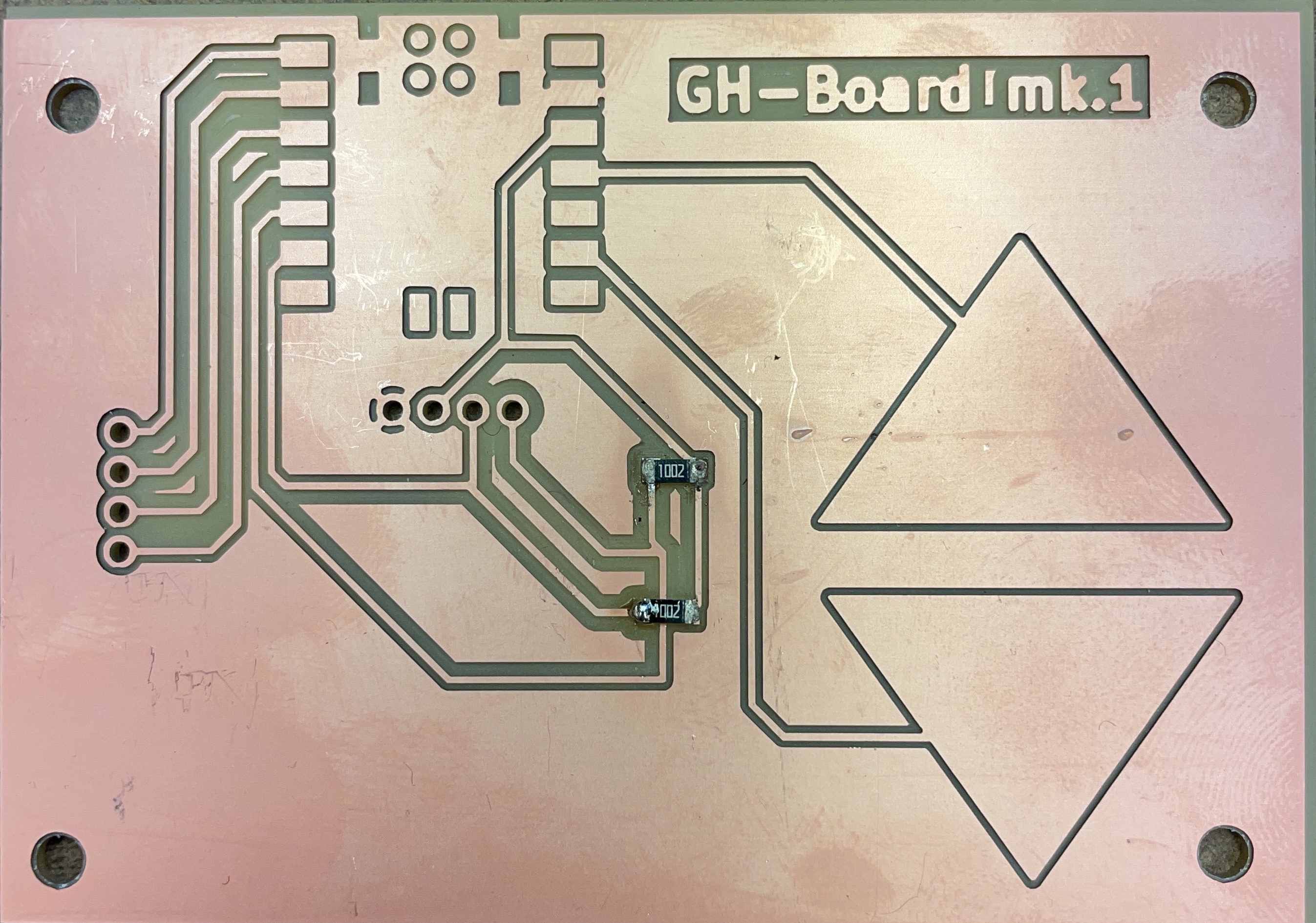
|  |
|:---------:|
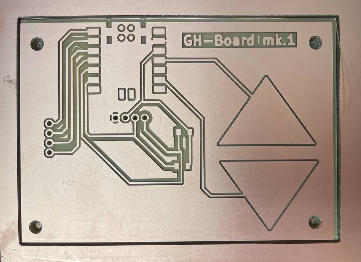
| *The milled board right out of the machine* |
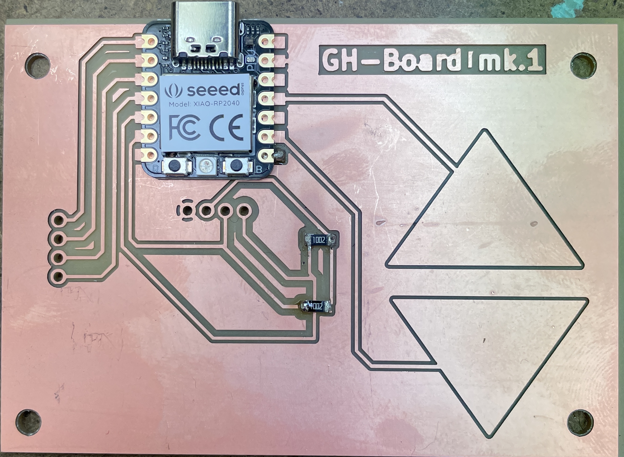
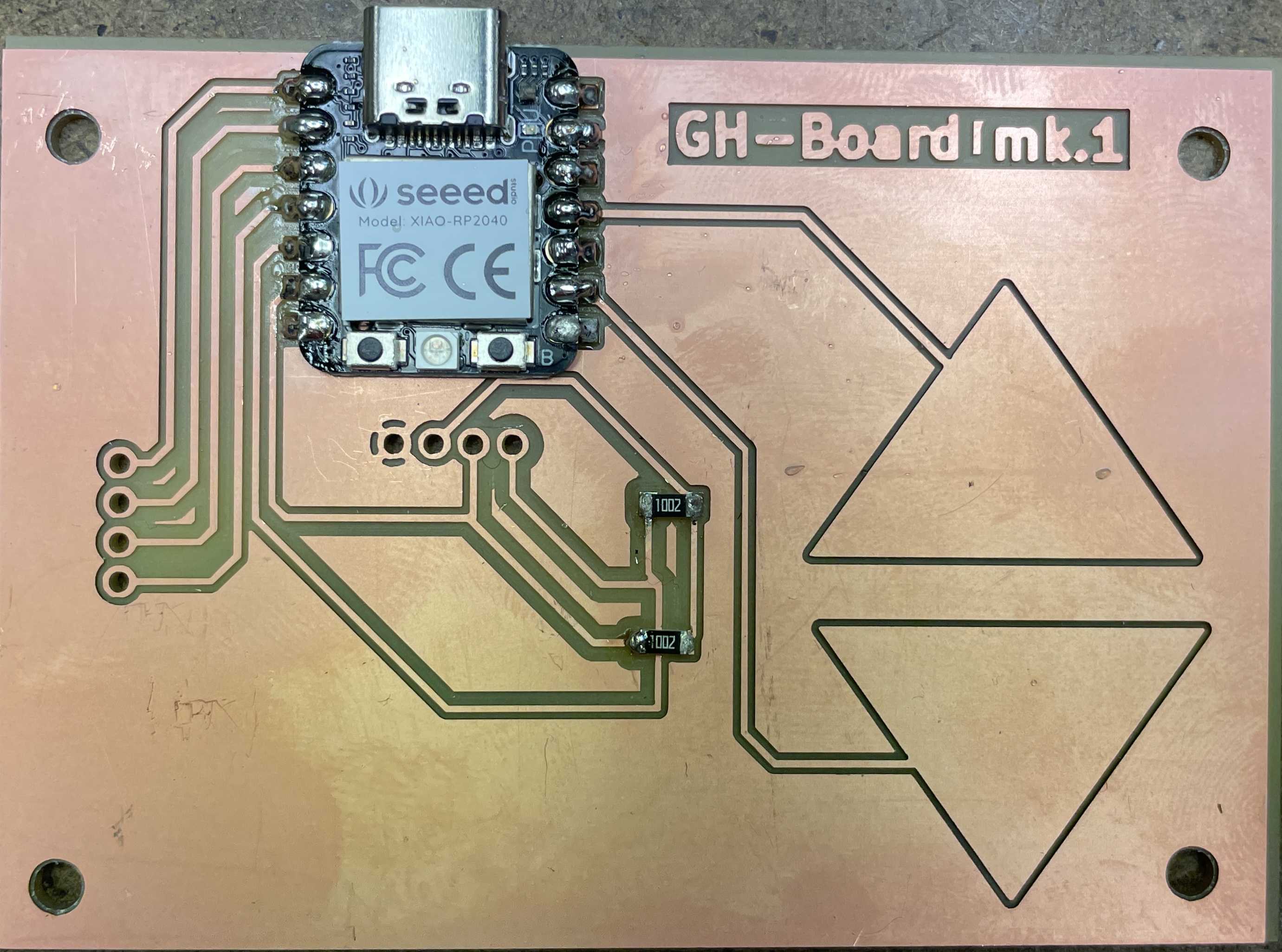
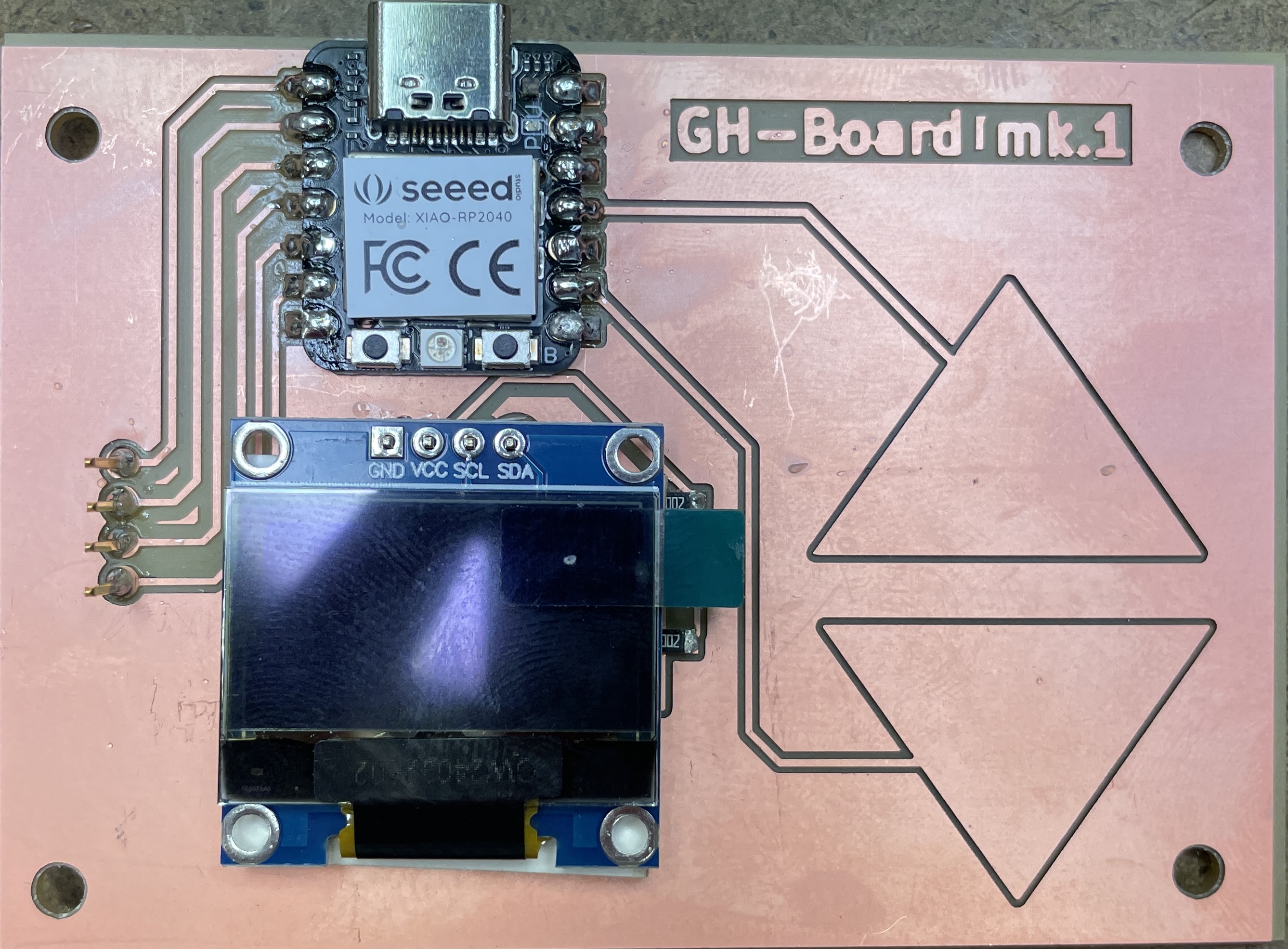
|  |
|:---------:|
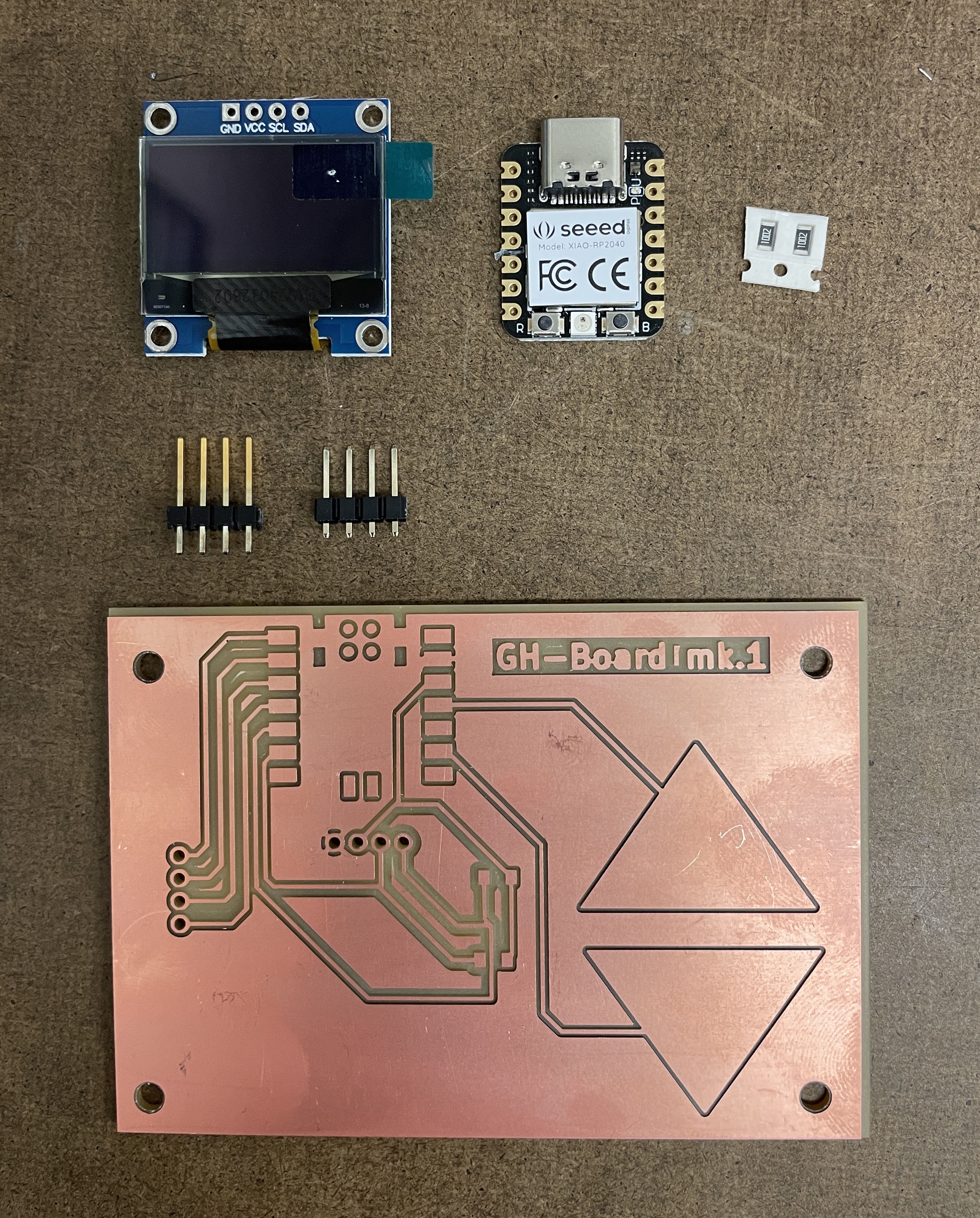
| *The board with all the components* |
The components I used include:
- two 10k resistors
- Seeed Xiao Breakout Board with RP2040 processor
- [B09JWN8K99 0.96 Inch OLED Module 12864](https://www.amazon.com/Self-Luminous-Display-Compatible-Arduino-Raspberry/dp/B09JWN8K99/?th=1)
- two breakout pin connectors, of 4 pins each
Here is the process of soldering it:
|  |  |  |
|:---------:|:---------:|:---------:|
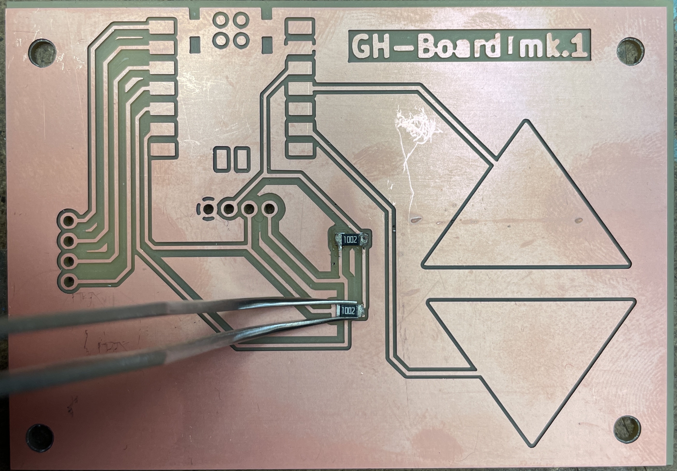
| *Tinning the contacts for the resistors, best to do just one side* | *Placing the resistor down with tweezers and soldering one side* | *Soldering the other side* |
|  |  |  |
|:---------:|:---------:|:---------:|
| *Placing the XIAO down with just one pin* | *Soldering all the other pins* | *Adding the two physical breakout pins* |
|  |  |  |
|:---------:|:---------:|:---------:|
| *Adding a piece of cardstock to protect the screen from short circuits* | *Placing the screen down on the pins* | *Soldering the screen* |
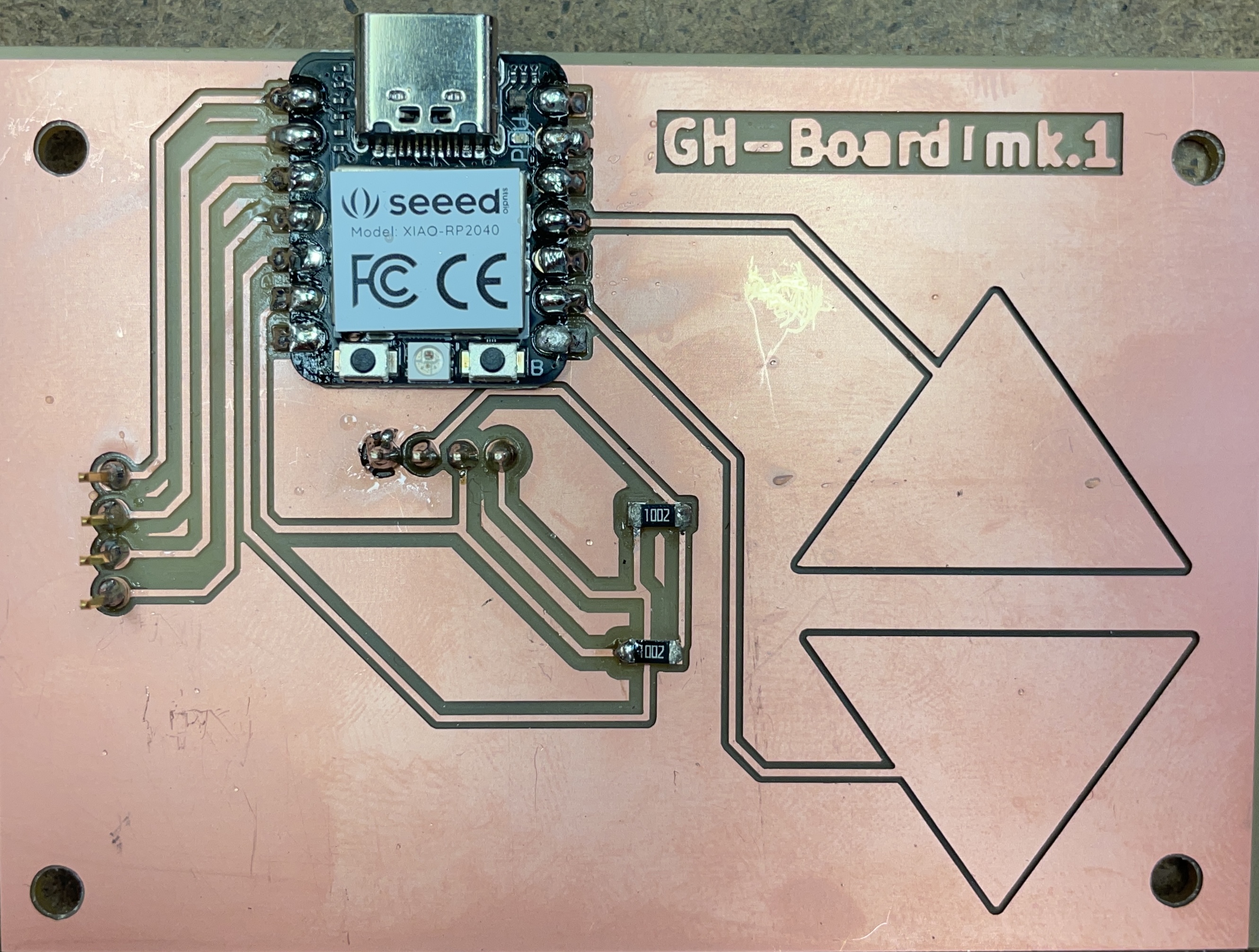
| 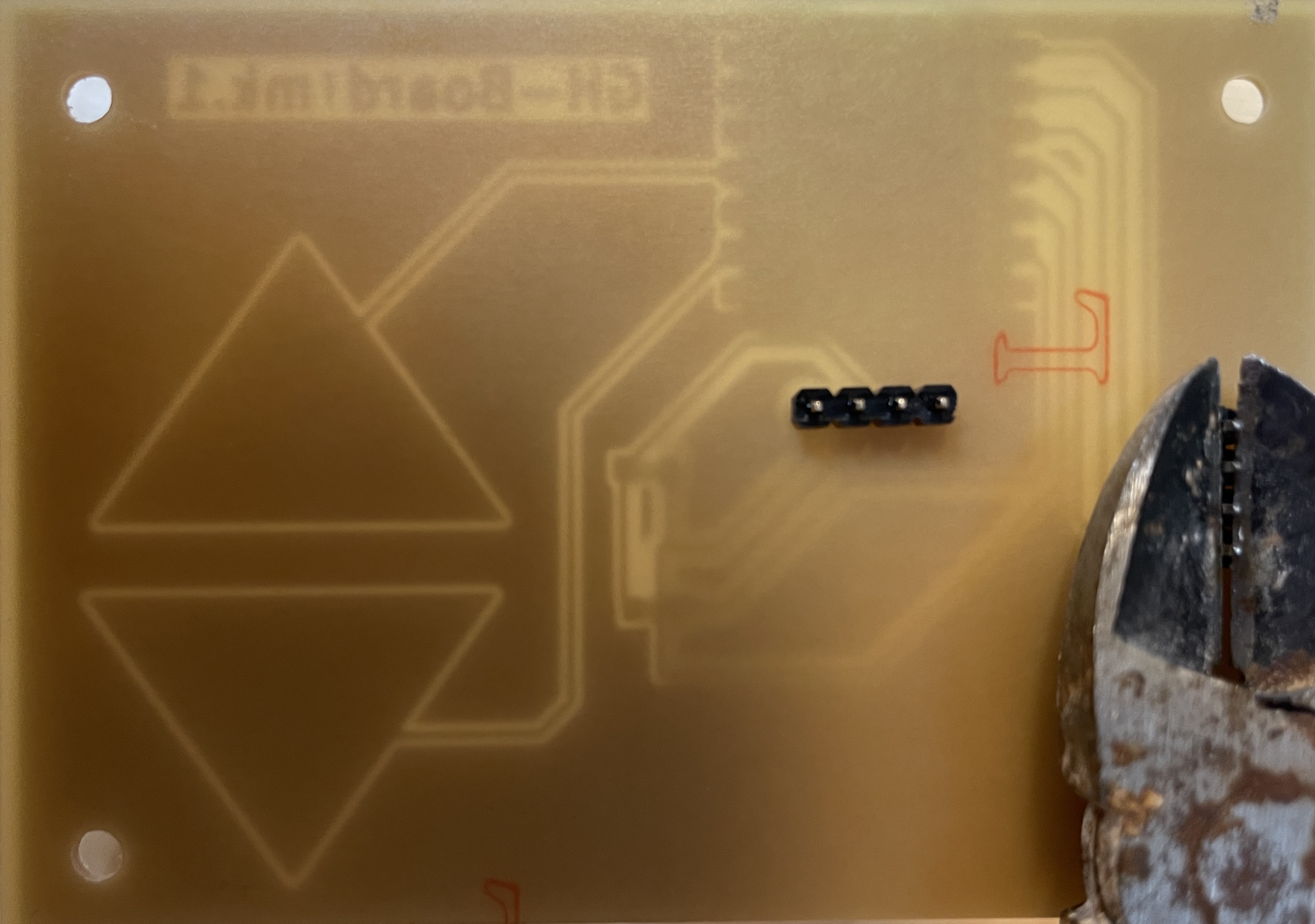 | 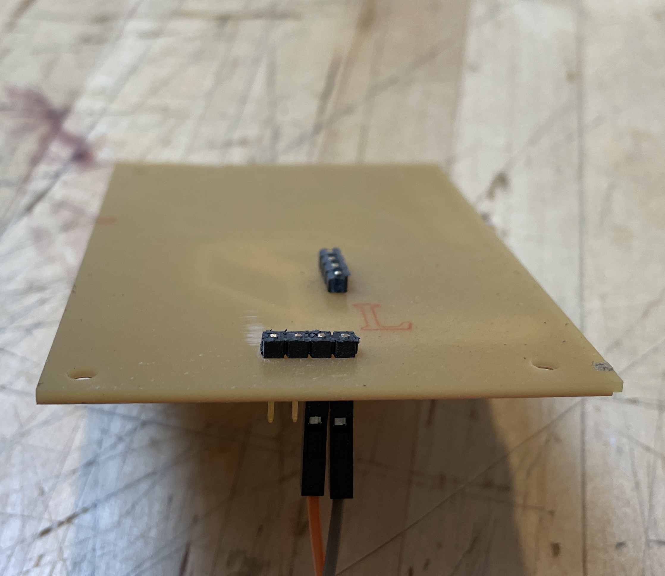 |
|:---------:|:---------:|
| *Snipping off the back of the pins with clippers* | *Filing down the back of the pins with a file* |
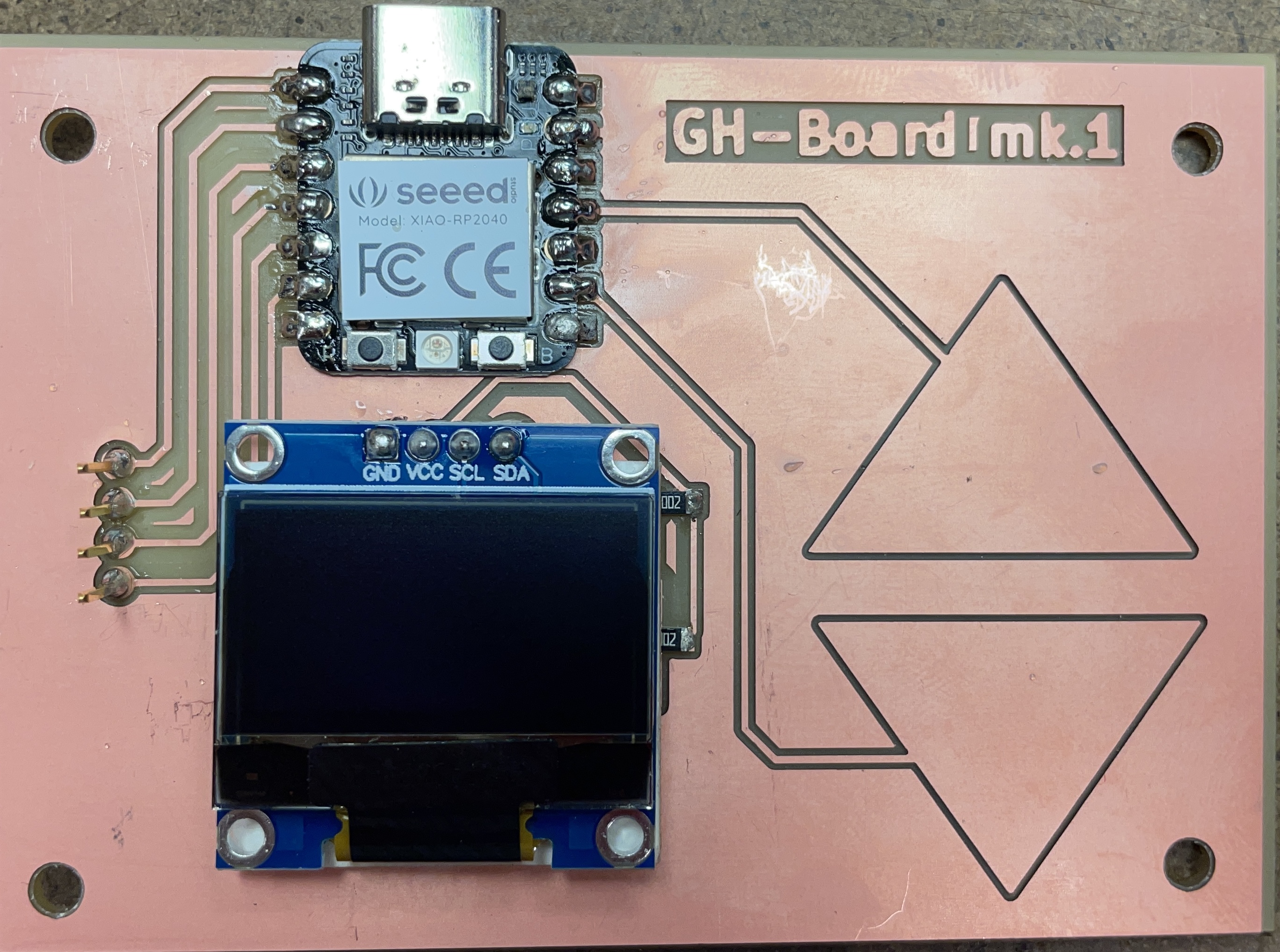
| 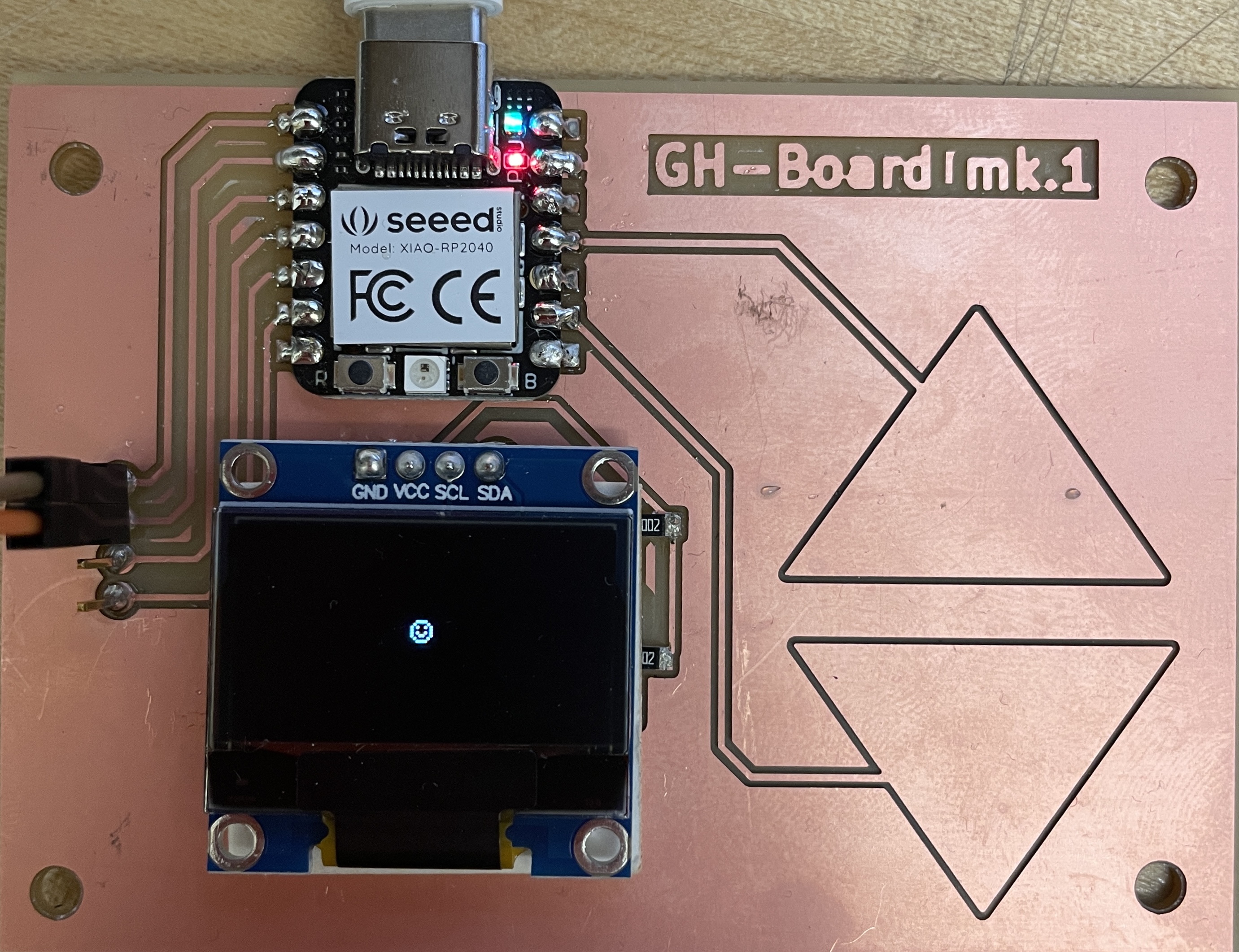 |
|:---------:|
| *The completed board is up and running* |
> Extra credit: make it with another process
[link-title](https://fab.cba.mit.edu/classes/863.25/)
## Attachments
[attachment-1.ext](files/attachment-1.ext)
## Acknowledgments