Week 3
Assignments: Embedded Programing
write and test a program for an embedded system using a microcontroller to interact (with local input &/or output devices) and communicate (with remote wired or wireless connections)
Steps
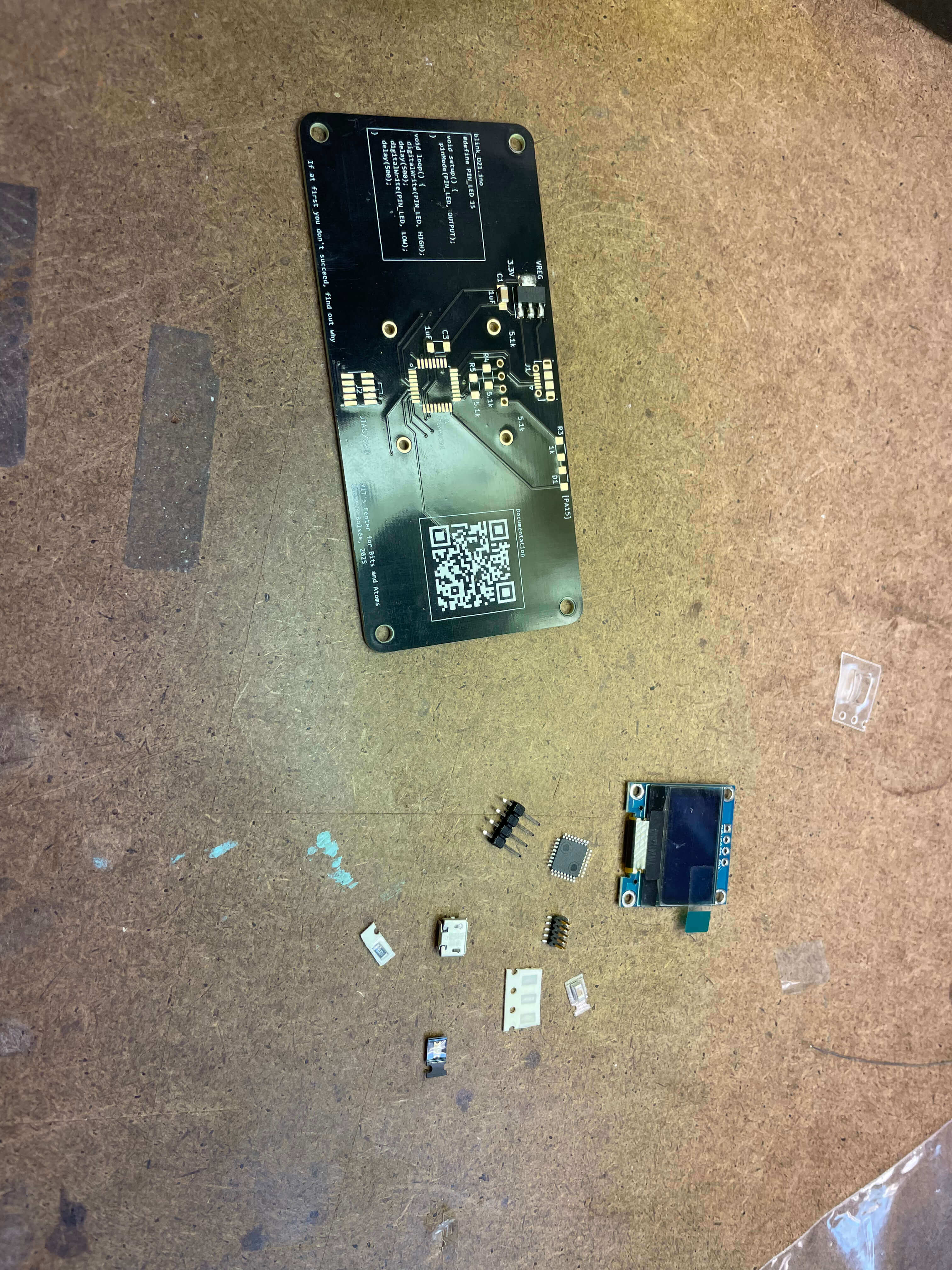
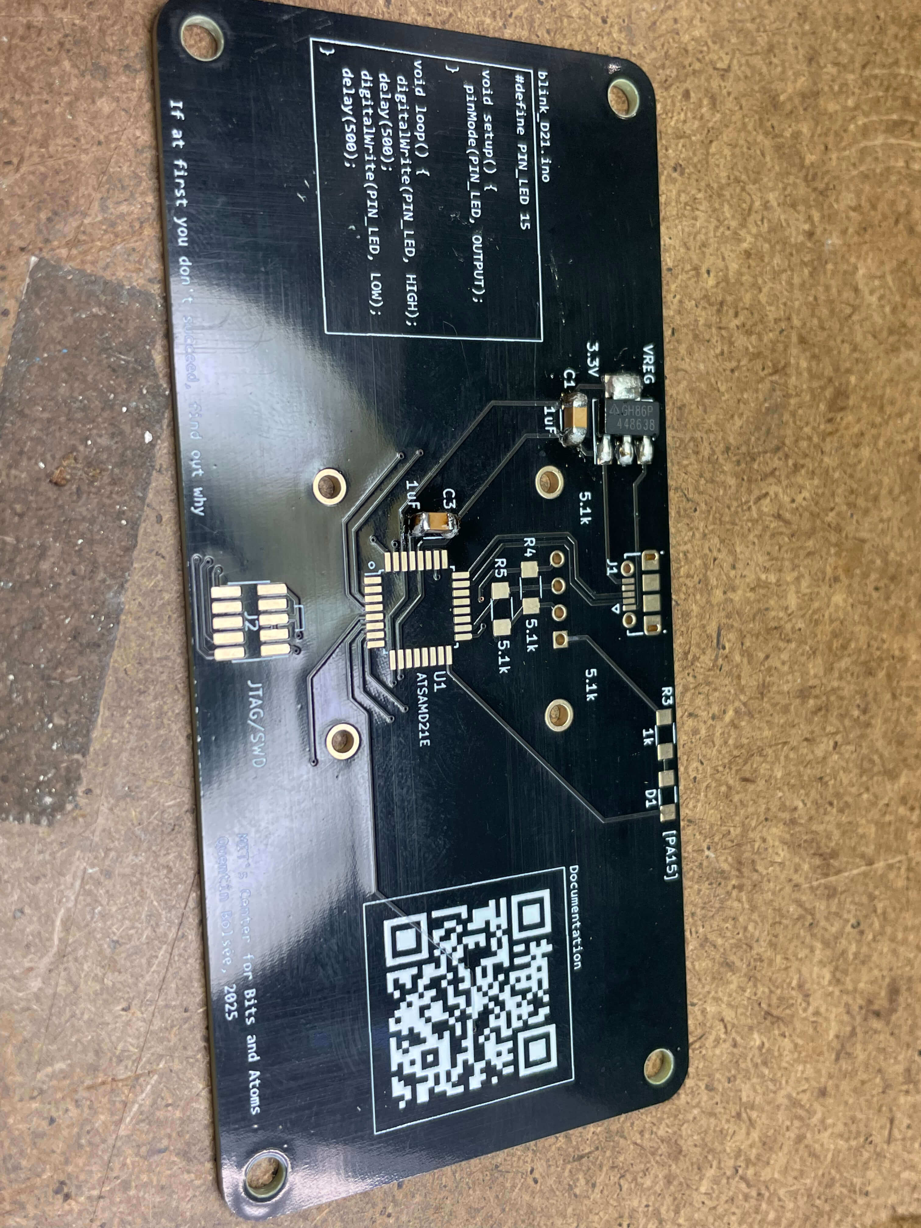
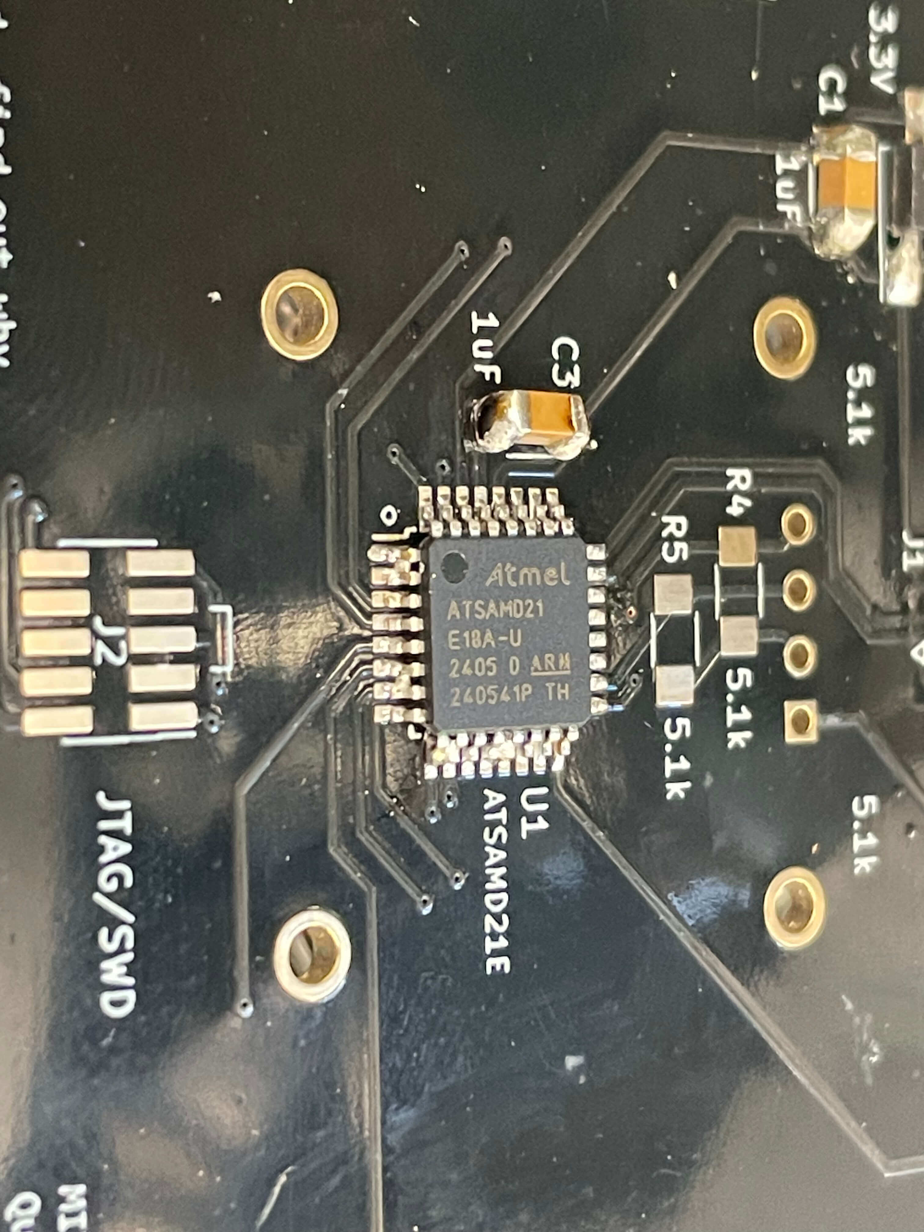
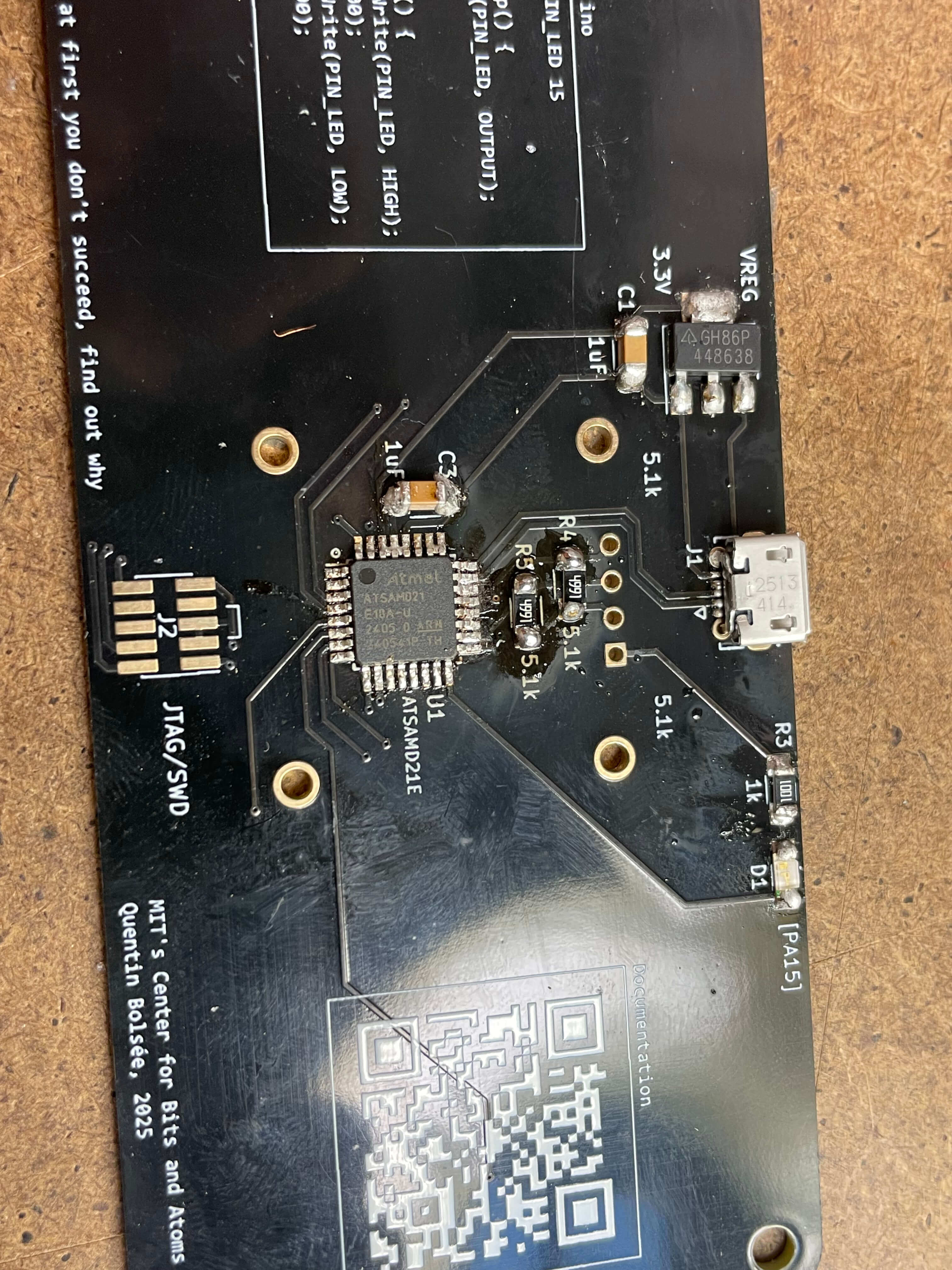
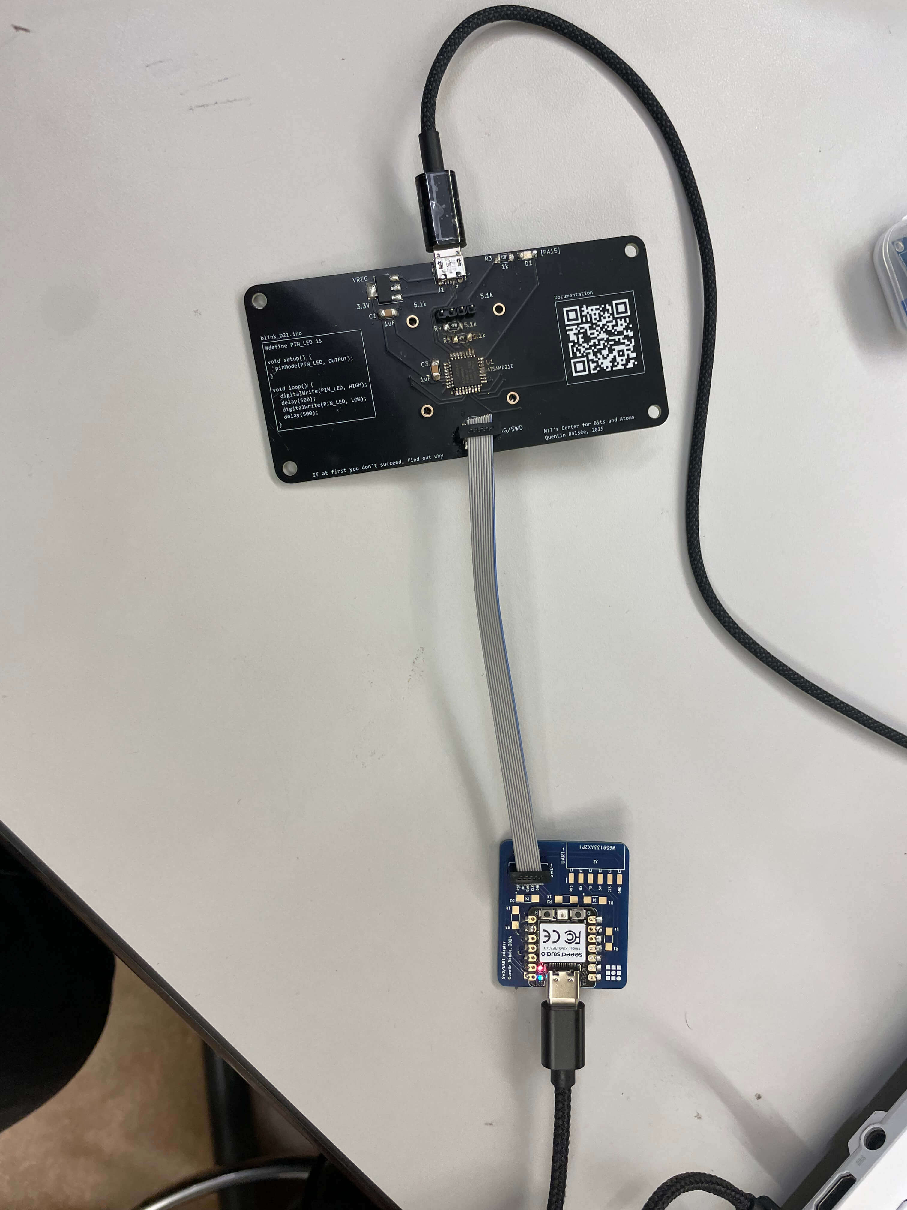
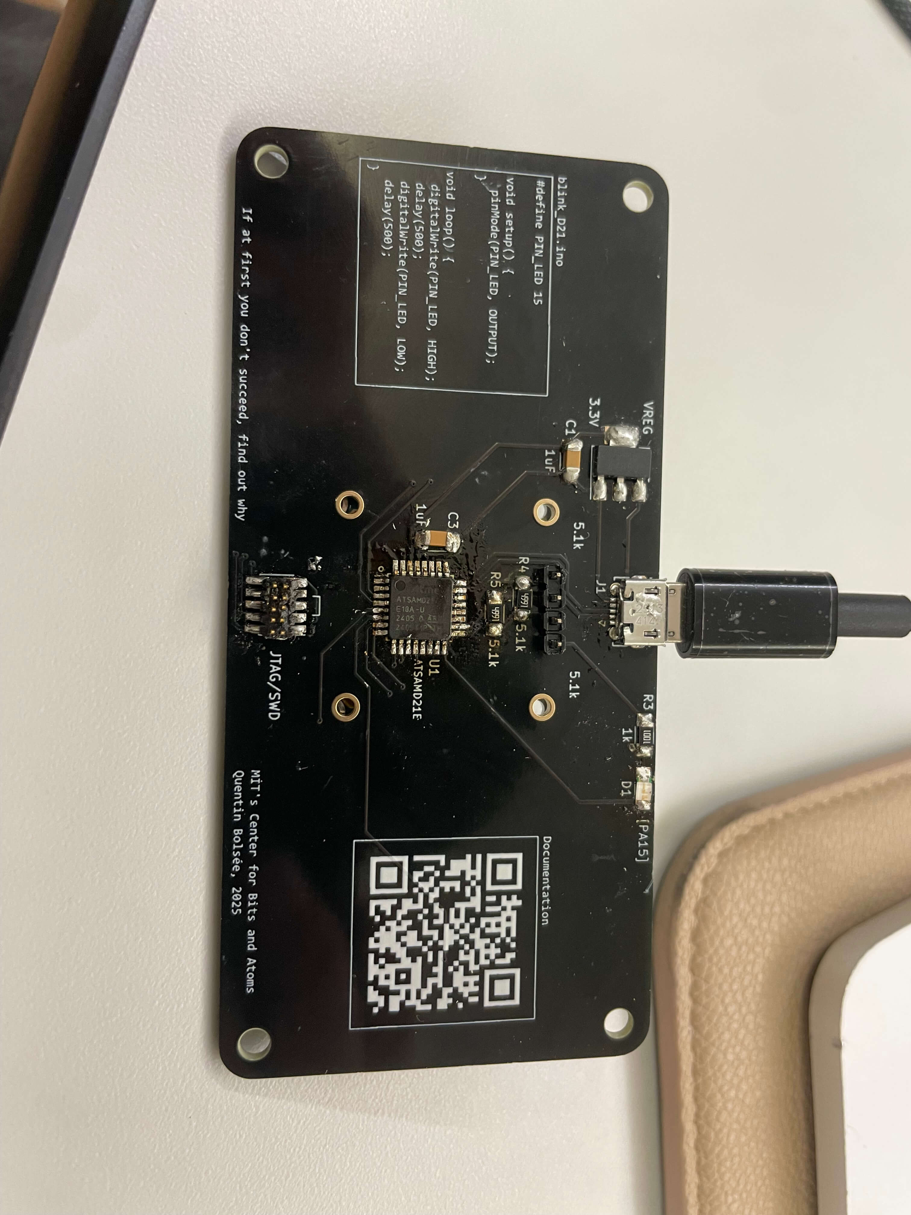
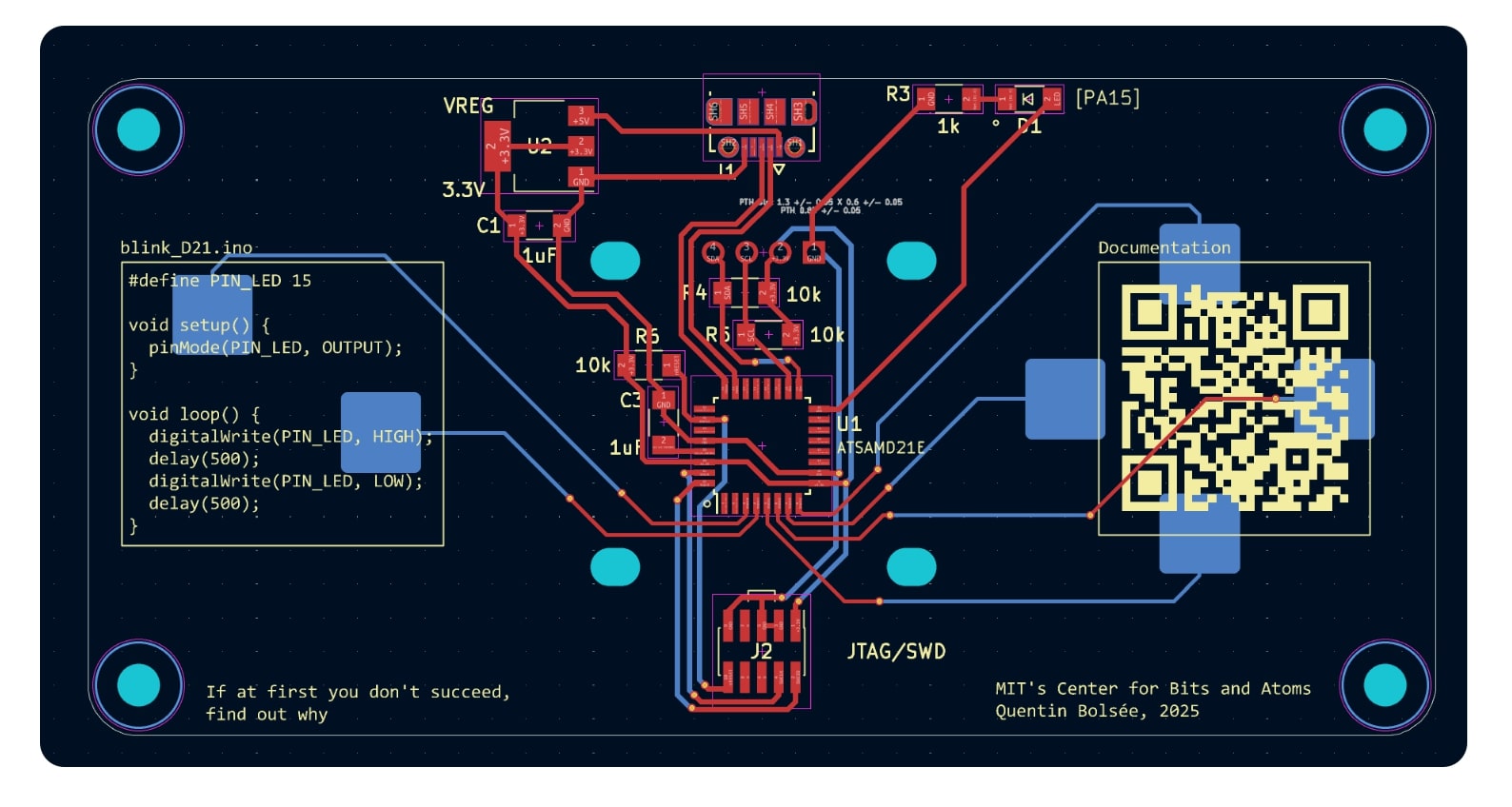
- I recieved a kit inclusive of a motherboard designed by the teaching team, and all the hardware components including a microcontroller, two 5k resistors, one 1k resistor, a small led, two capacitors, a header that would ultimately recieve a bootloader, a voltage regulator, and a usb port for transfer of power and data. (fig 1)
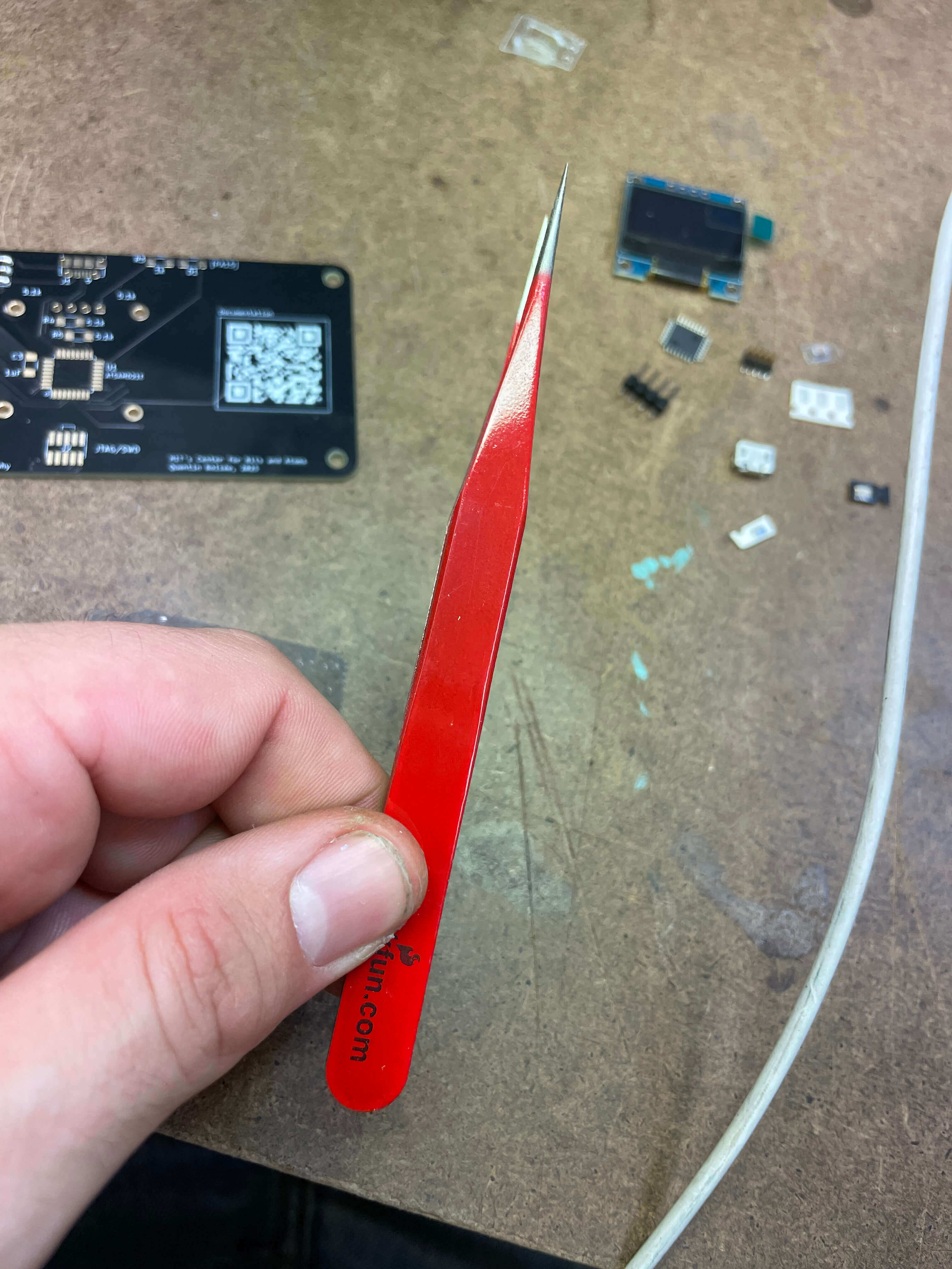
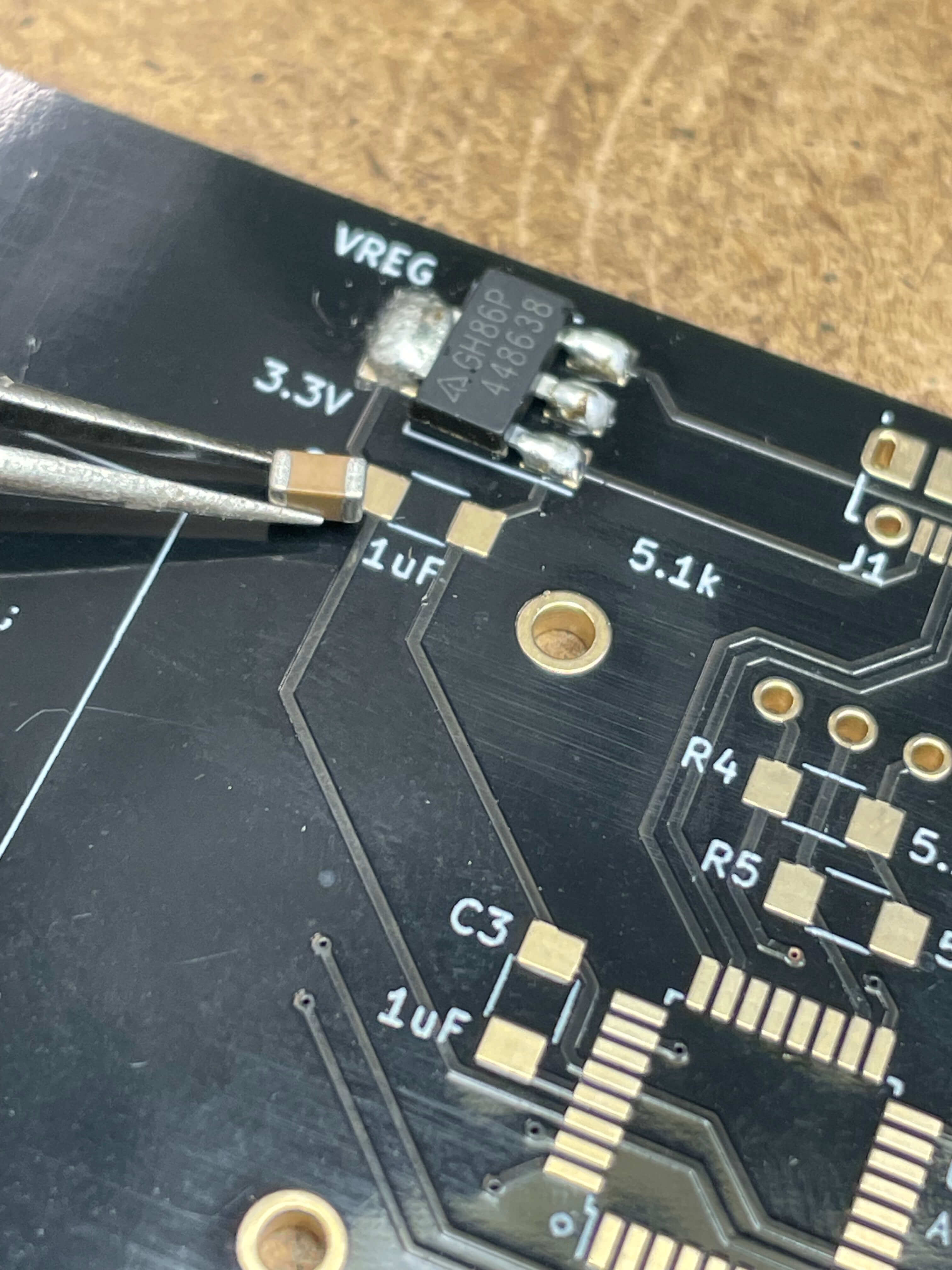
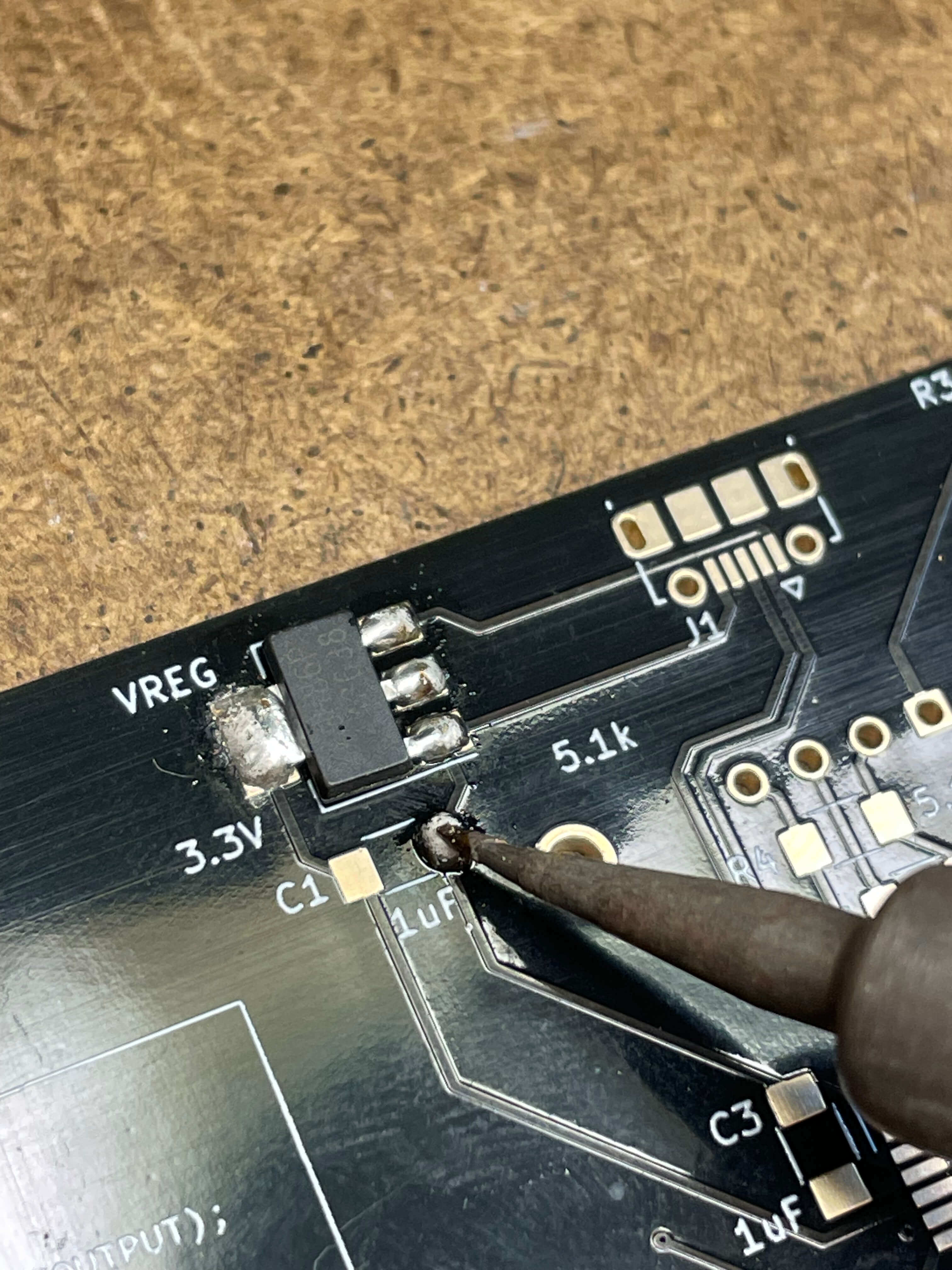
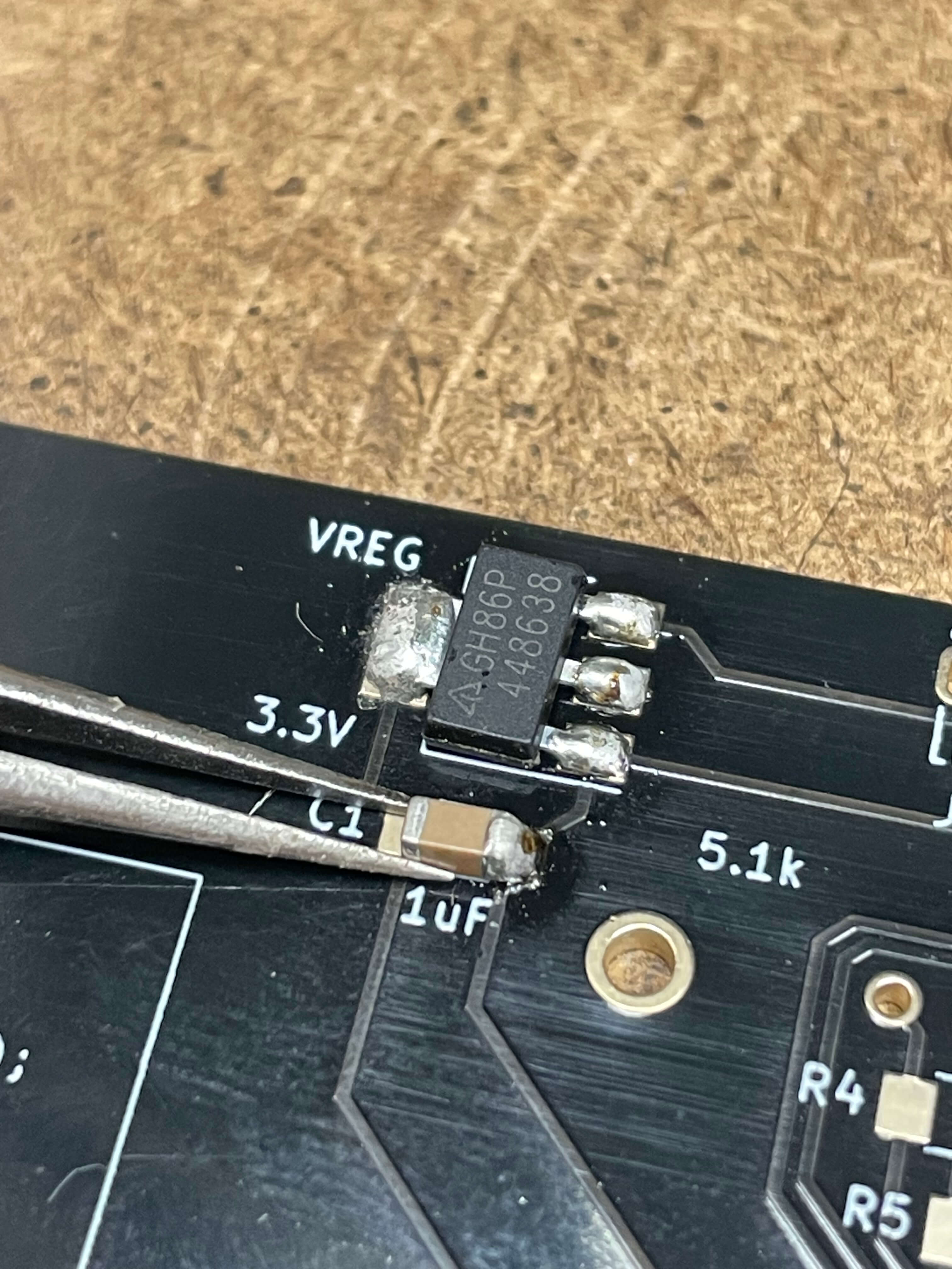
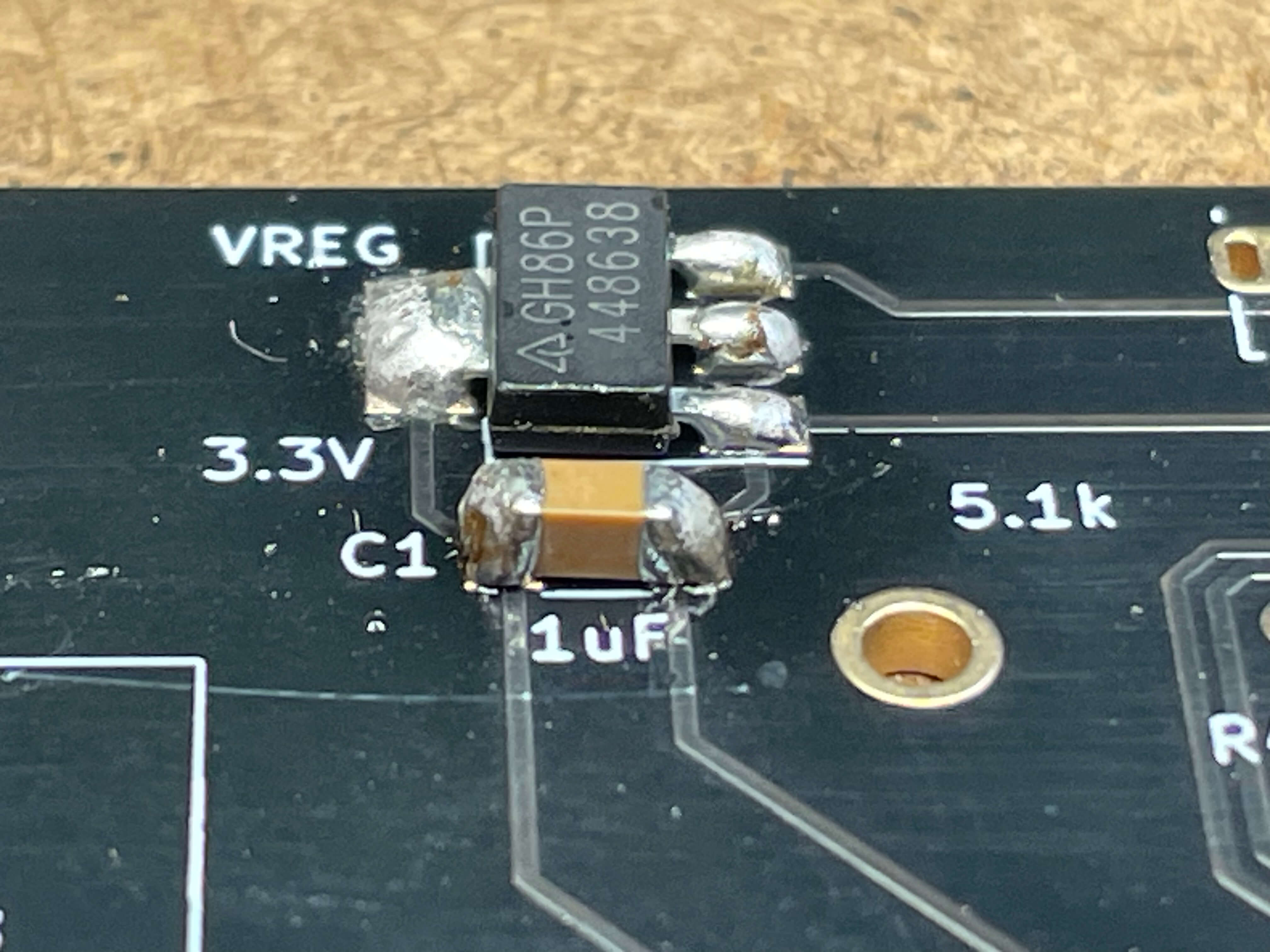
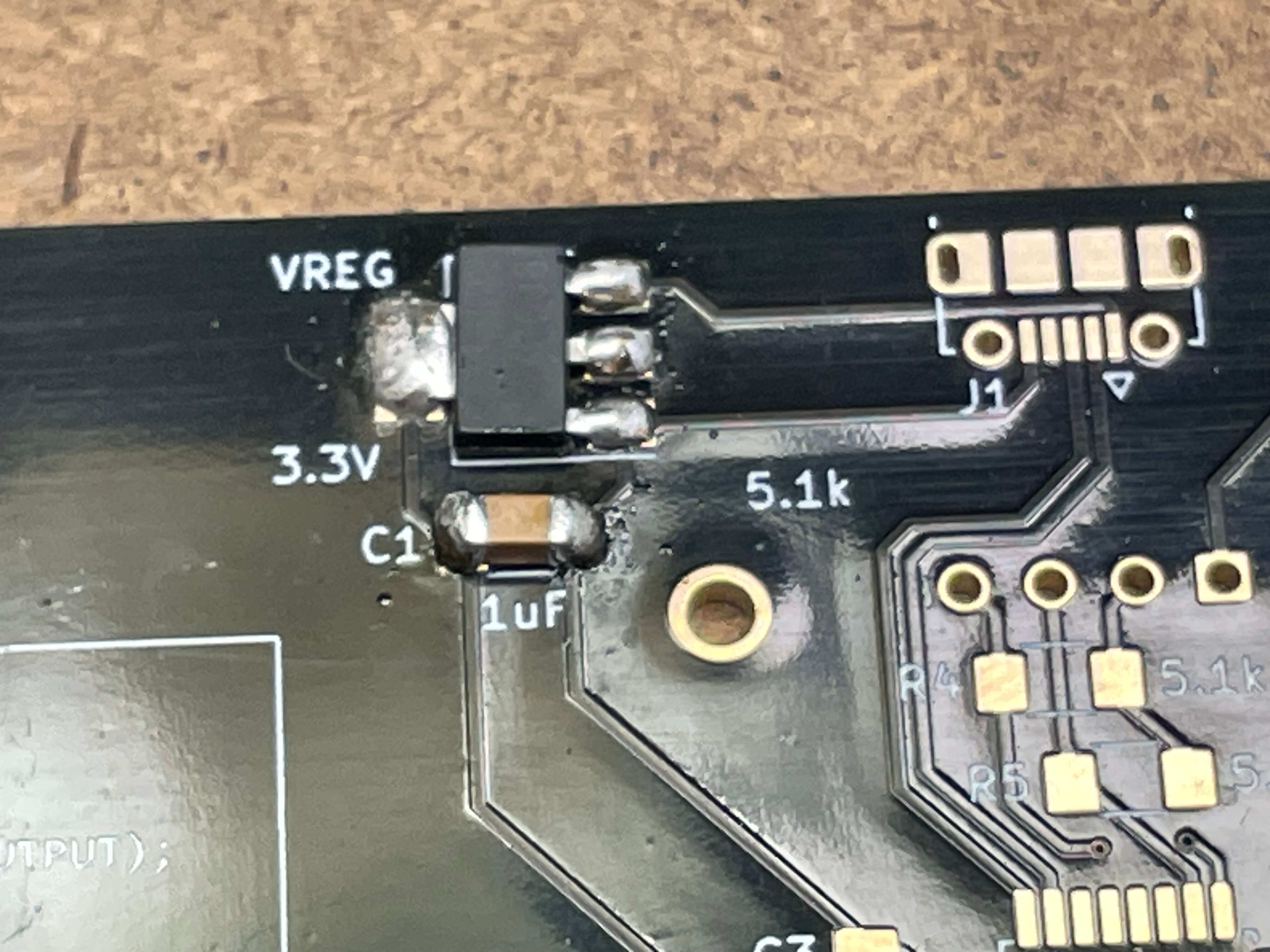
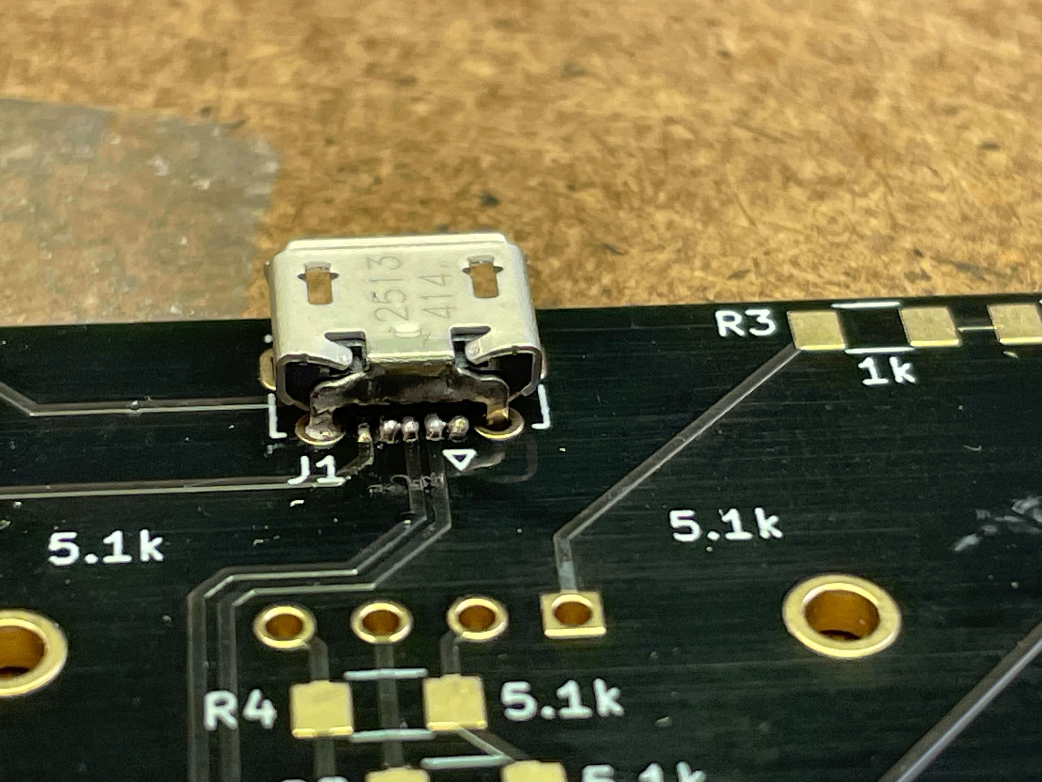
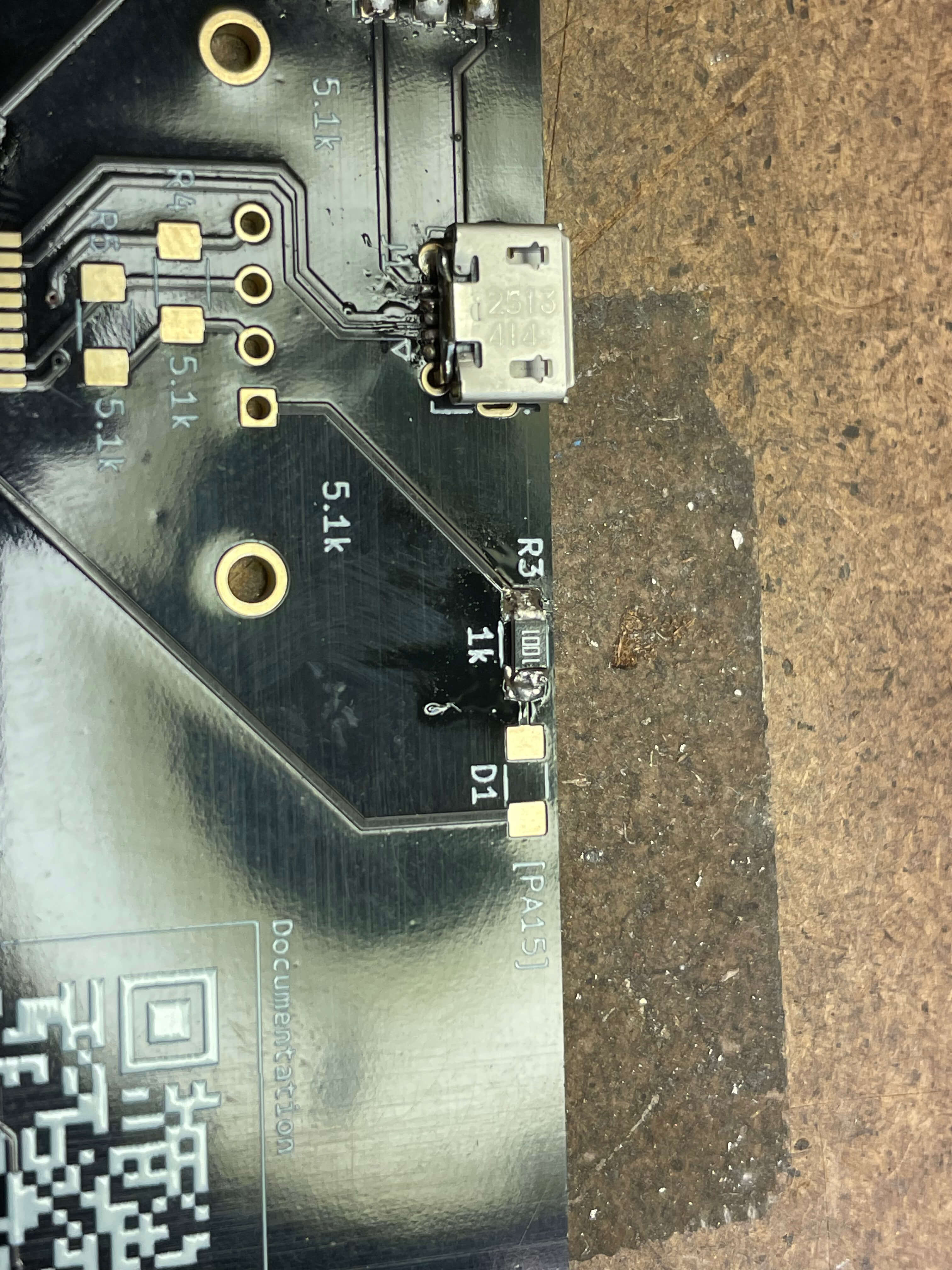
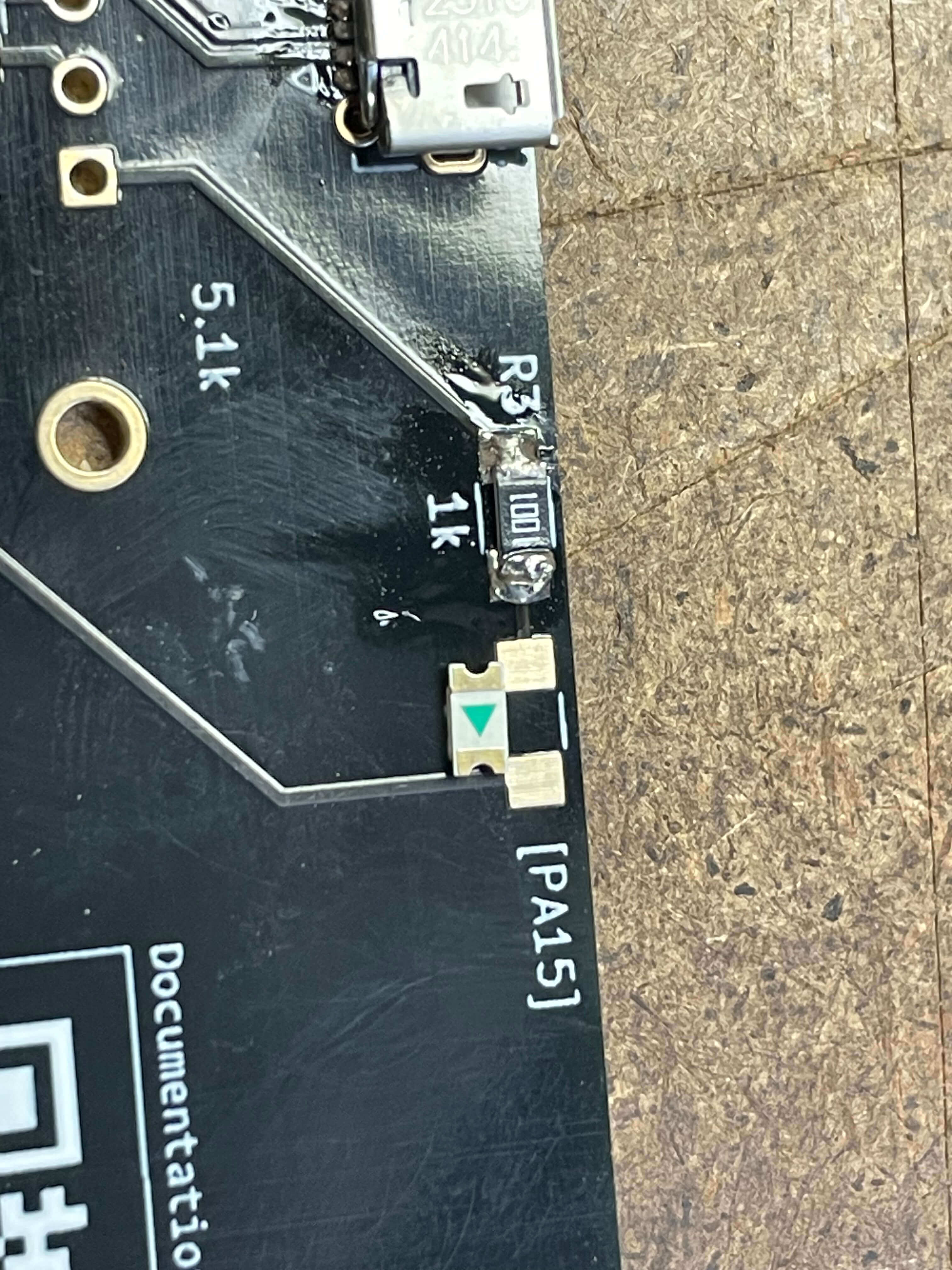
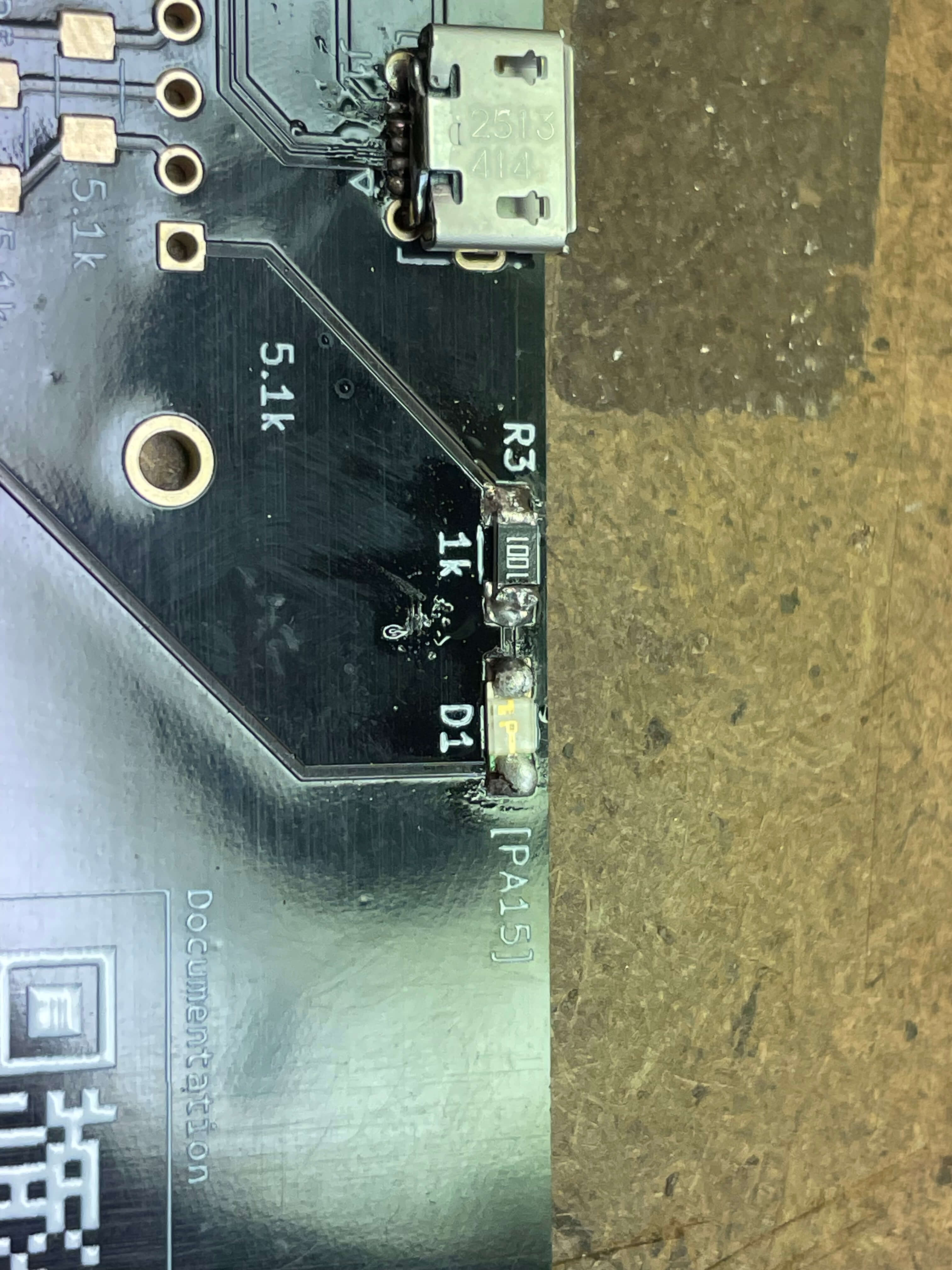
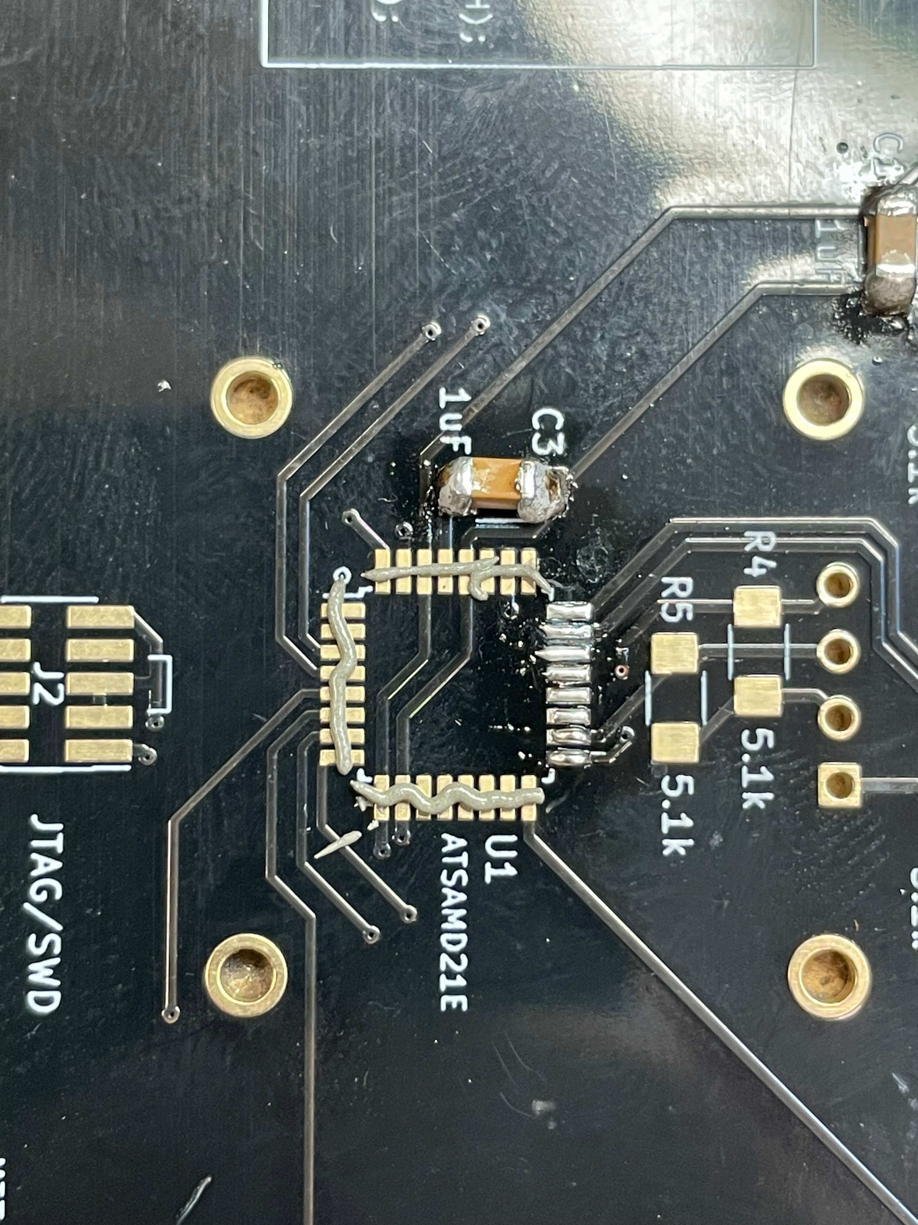
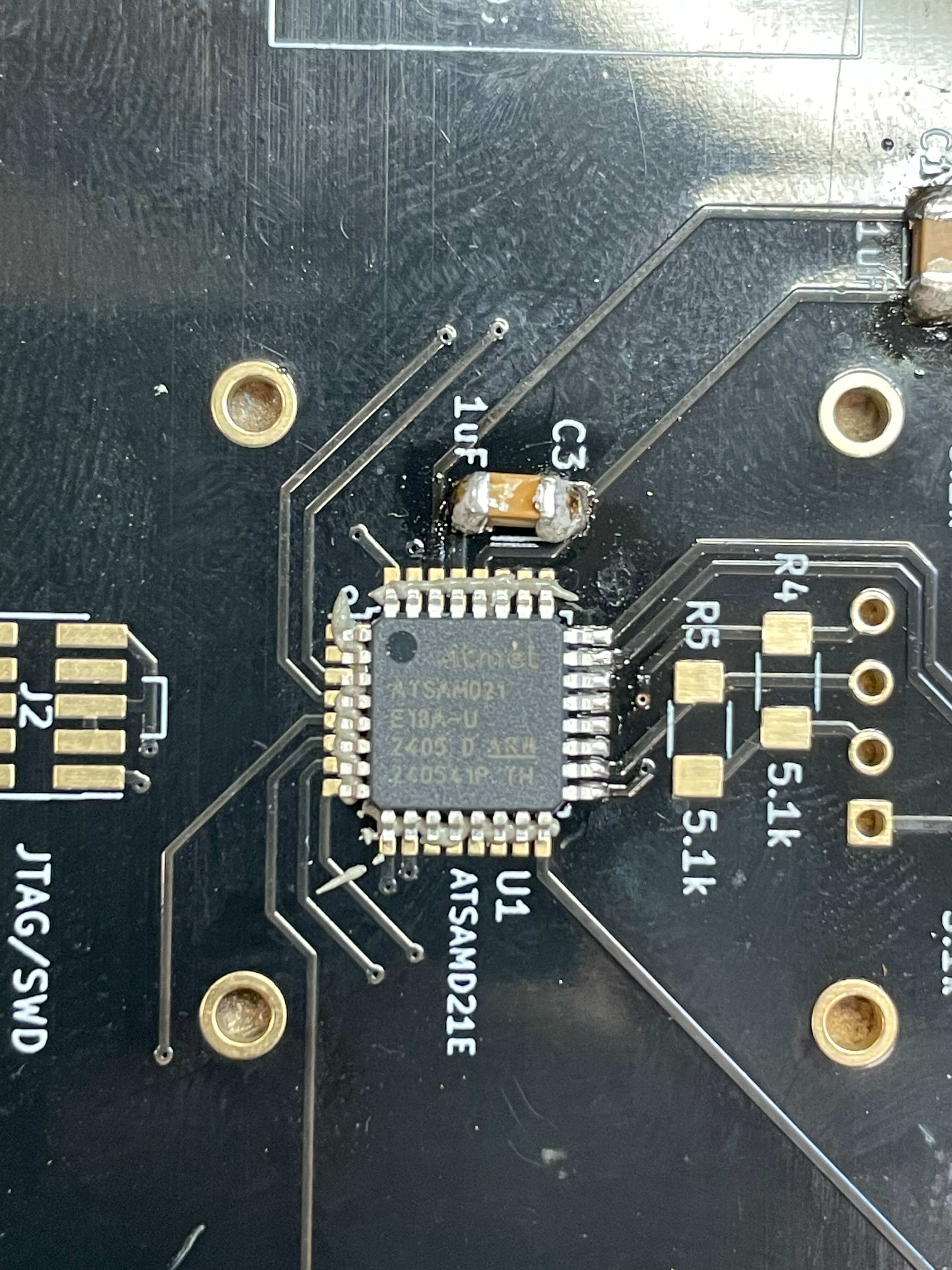
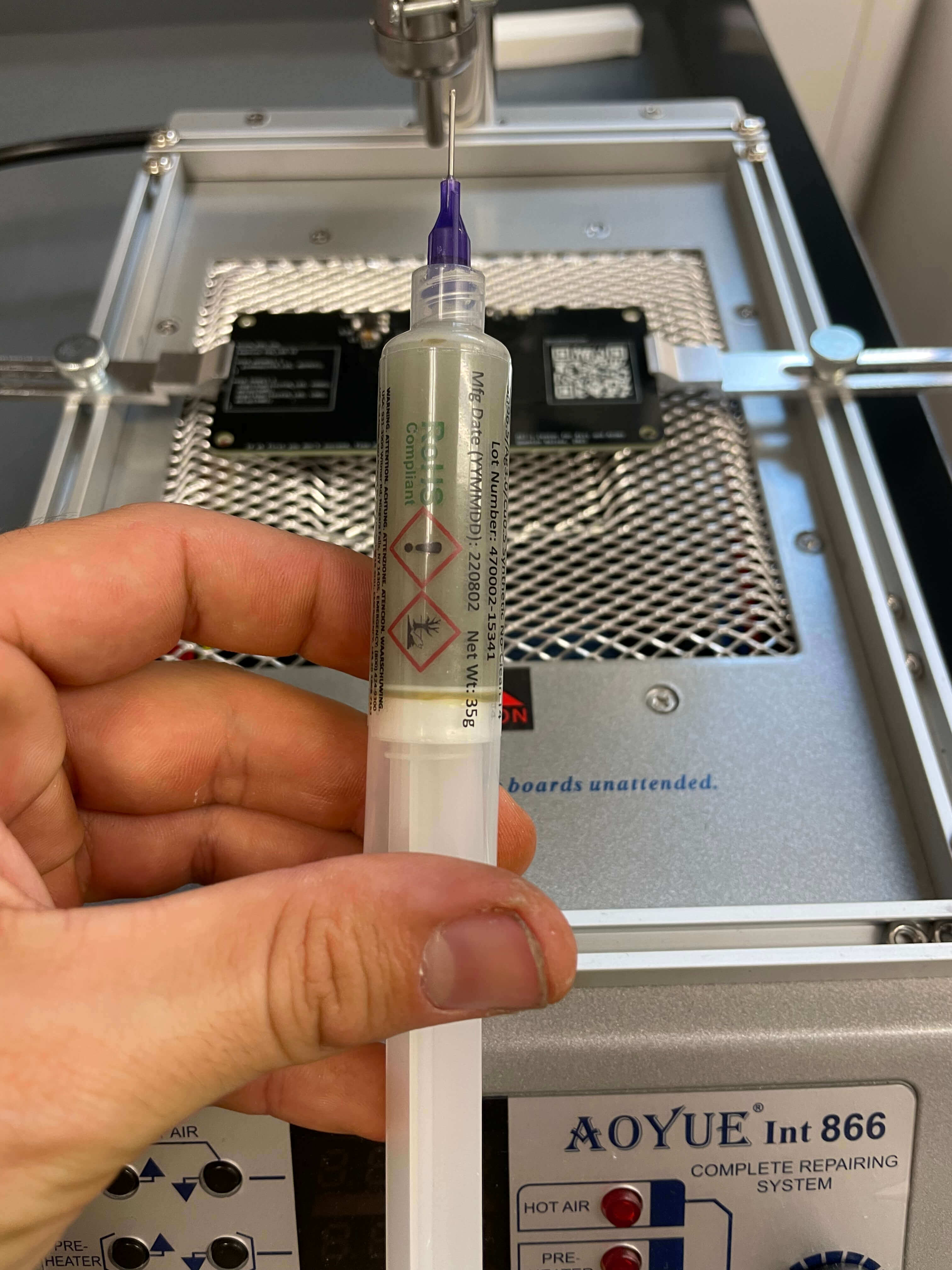
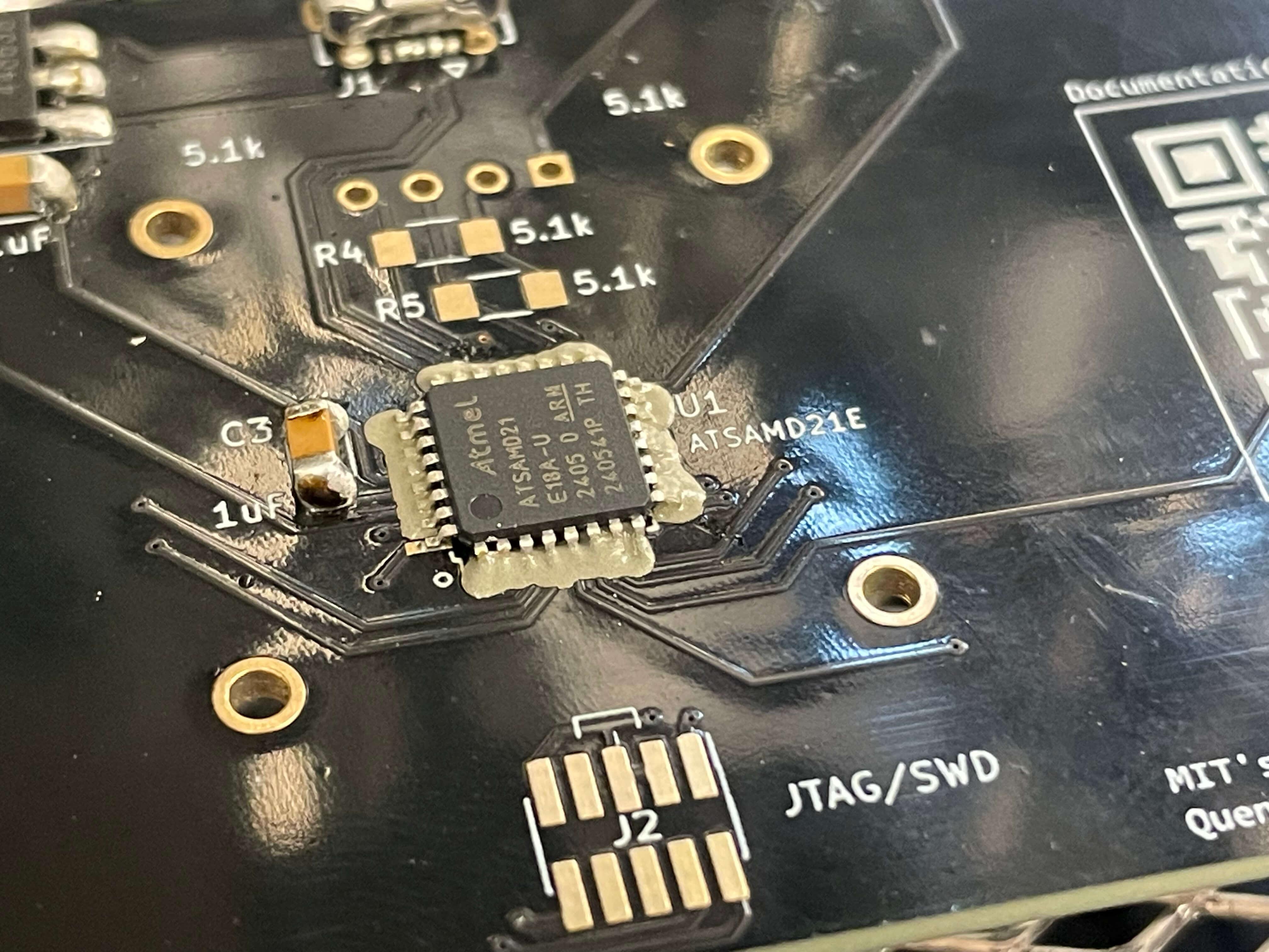
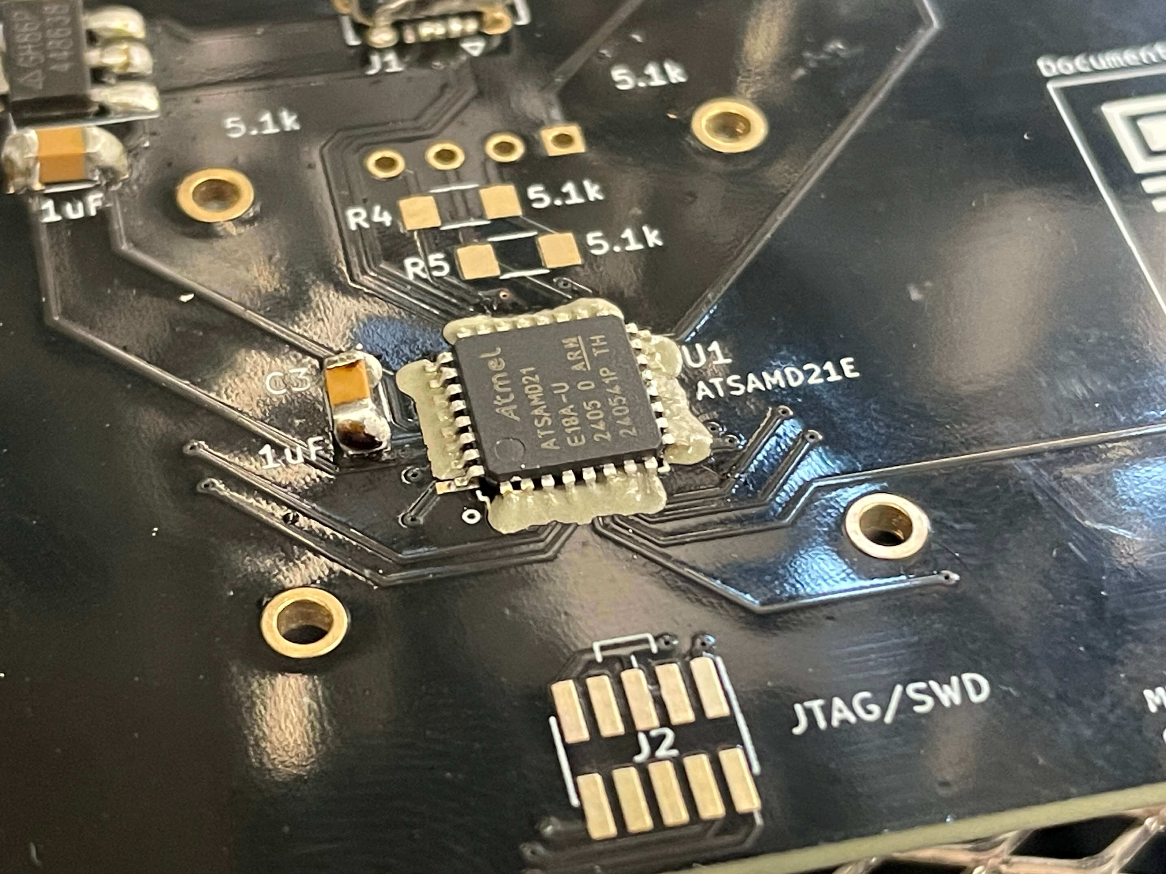
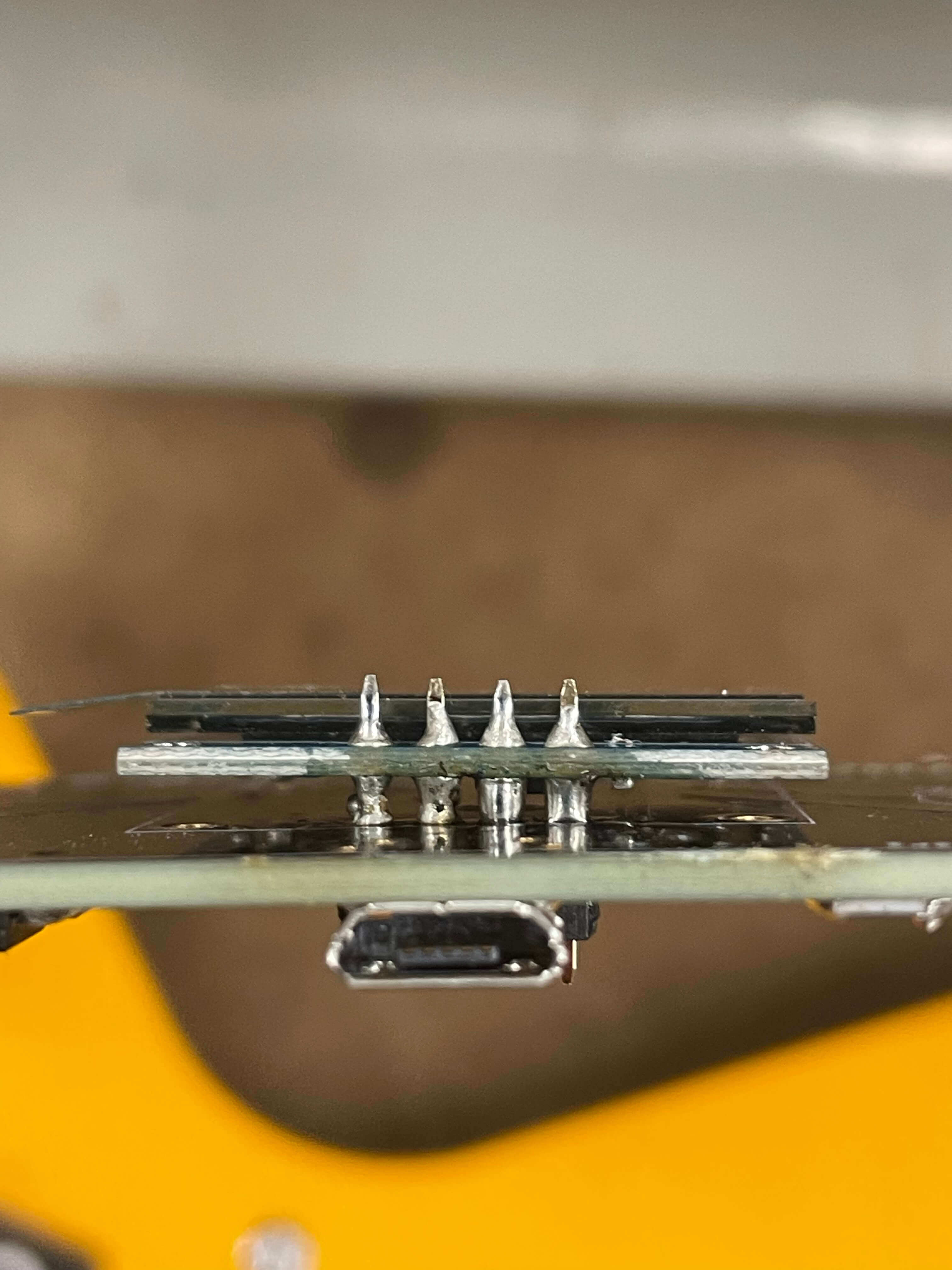
- Using soldering tools including a fan, iron, nonleaded thin solder, tweezers, solder paste, and a heat gun soldering iron, and a large screen stereo microscope to check the quality of my connections. I spent many hours troubleshooting with the solder wicking copper, and deposing and redepositing solder, alternating between the heat gun and the iron to test techniques and avoid spending too much time hand soldering each of the small pins on the microcontrollers and the headders. The heatgun did start to melt some plastic of several components, and I resolved to fix the majority of solders by hand with the iron. Problems encountered and lessons learned are largely that a larger iron that heats well is indeed way more usefull than a small precise iron that wont melt solder. See enlarged microscope photos as well (fig 2-35)
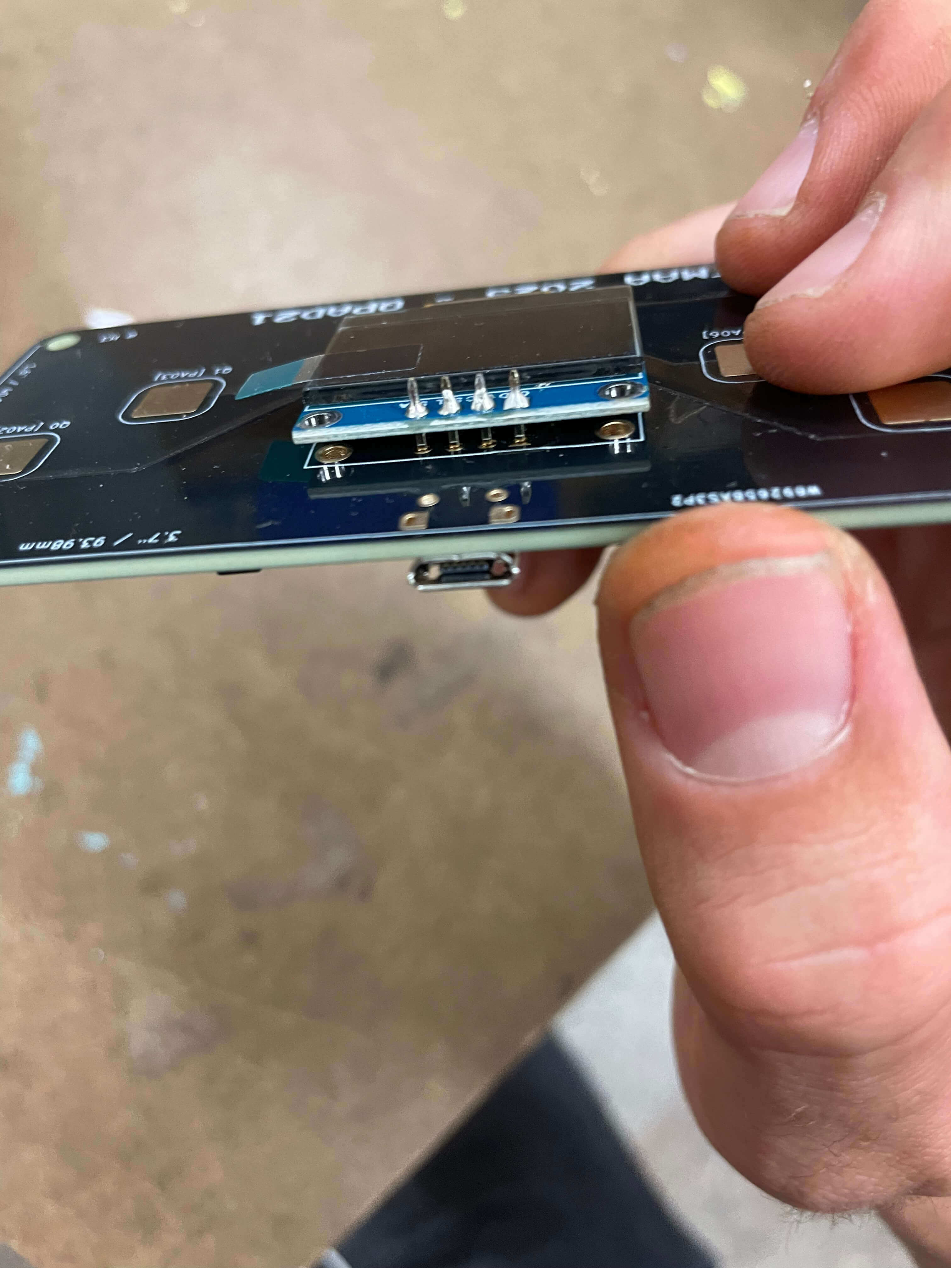
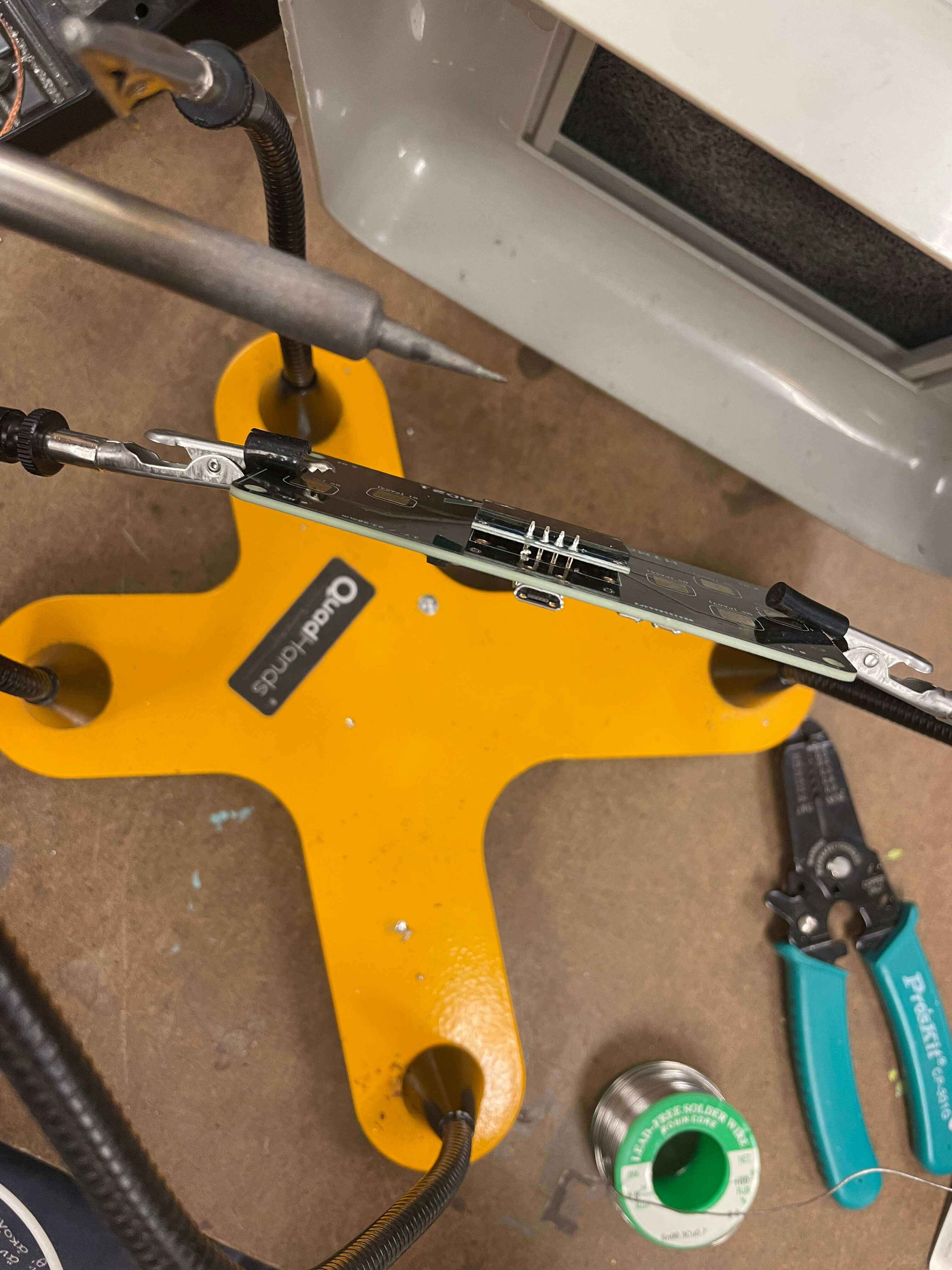
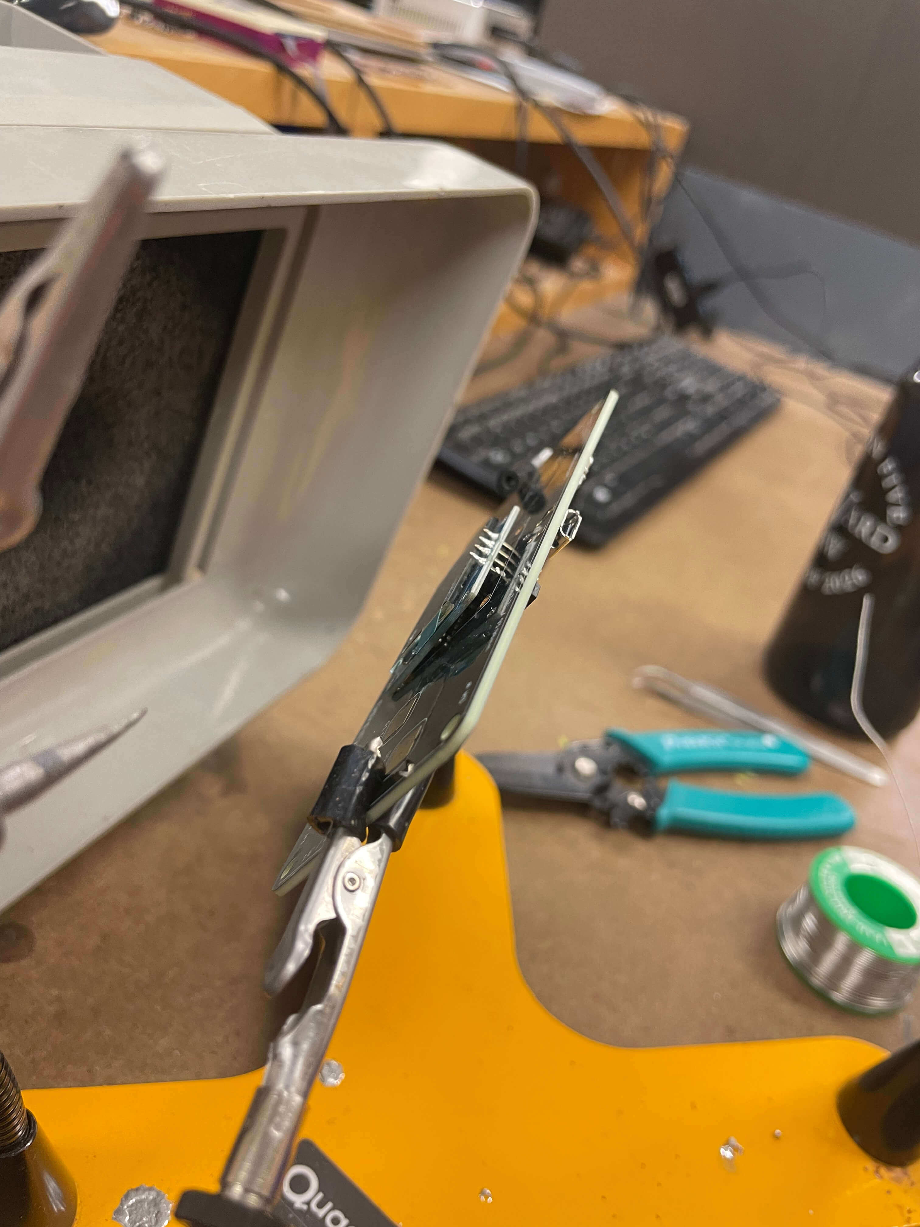
- I had flipped the hardware connection for the screen mount, (fig 36-38), and as a result I needed to use aligator clip welding arms to hold the board so that I could flood the pegs with solder to fix the board into place since the plastic spacer did get in the way of soldering onto the front face of the hardware side - opposite the screen side.
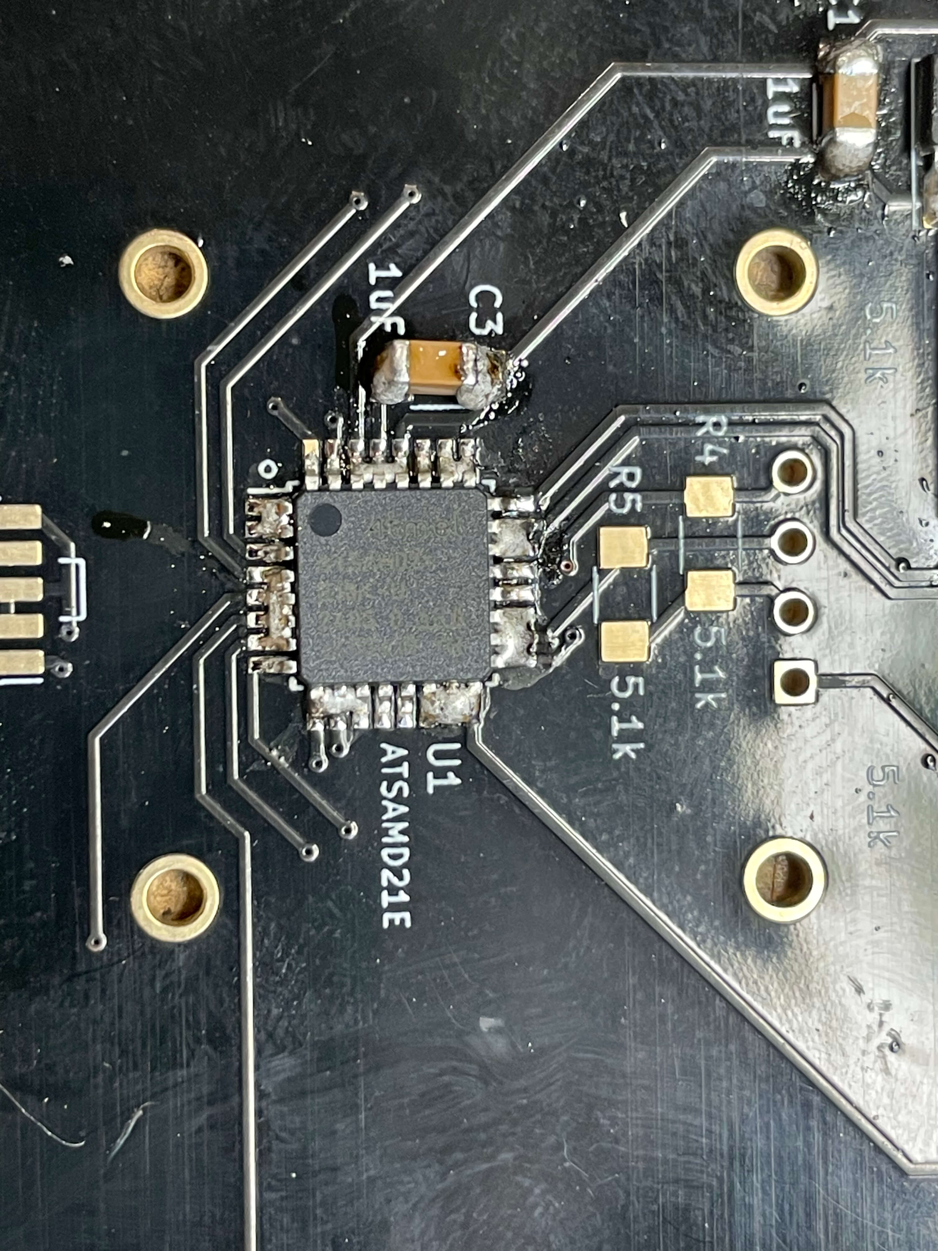
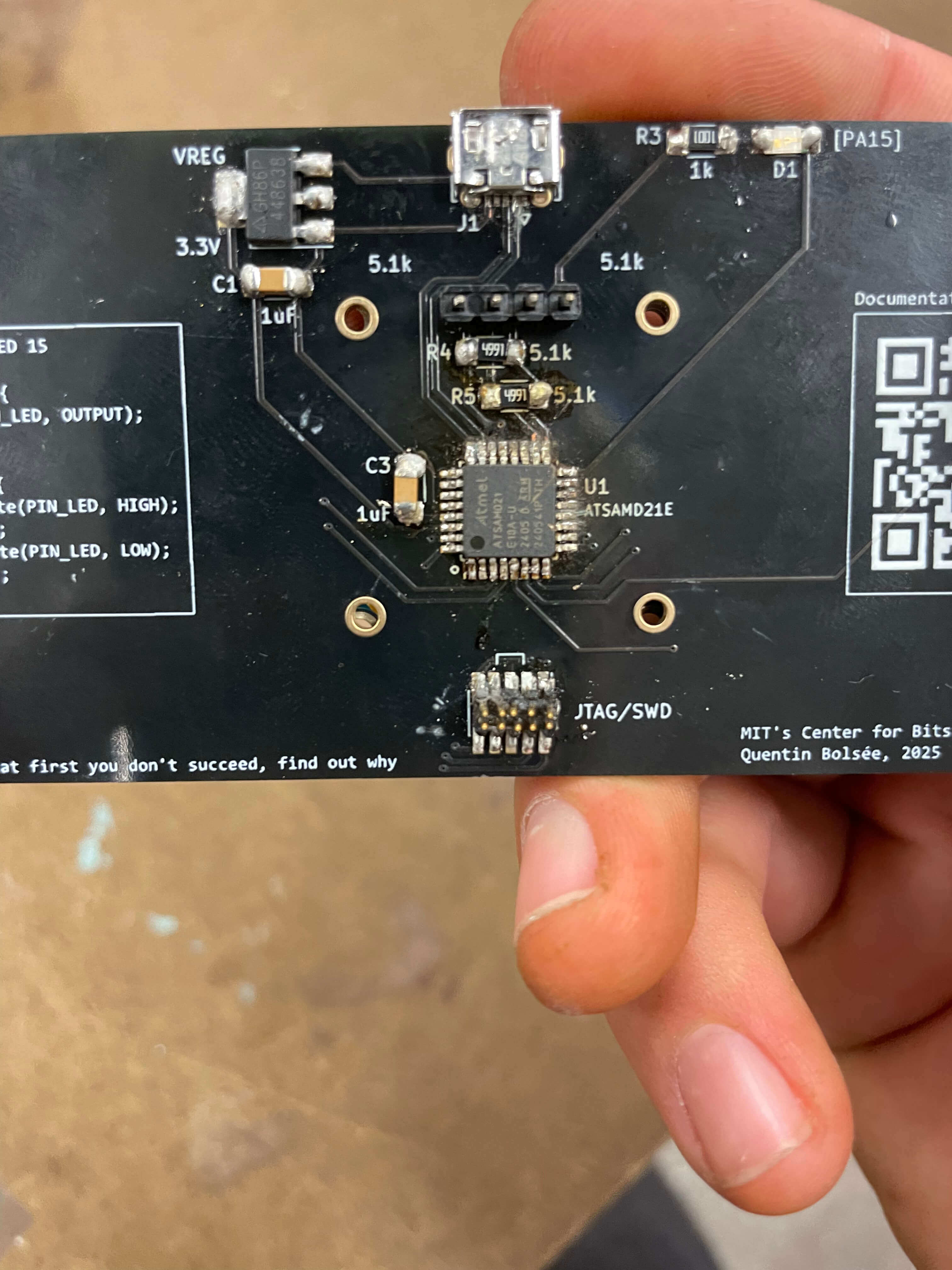
- I brought my board into get help with the boot loader monday evening, and was skeptical I had soldered eveything correctly. It seemed entirely possible that I hand produced several moments of short circuit, and had also gotten my solders down to not much material so i was worried about strength of connetcion. (fig 30-35)
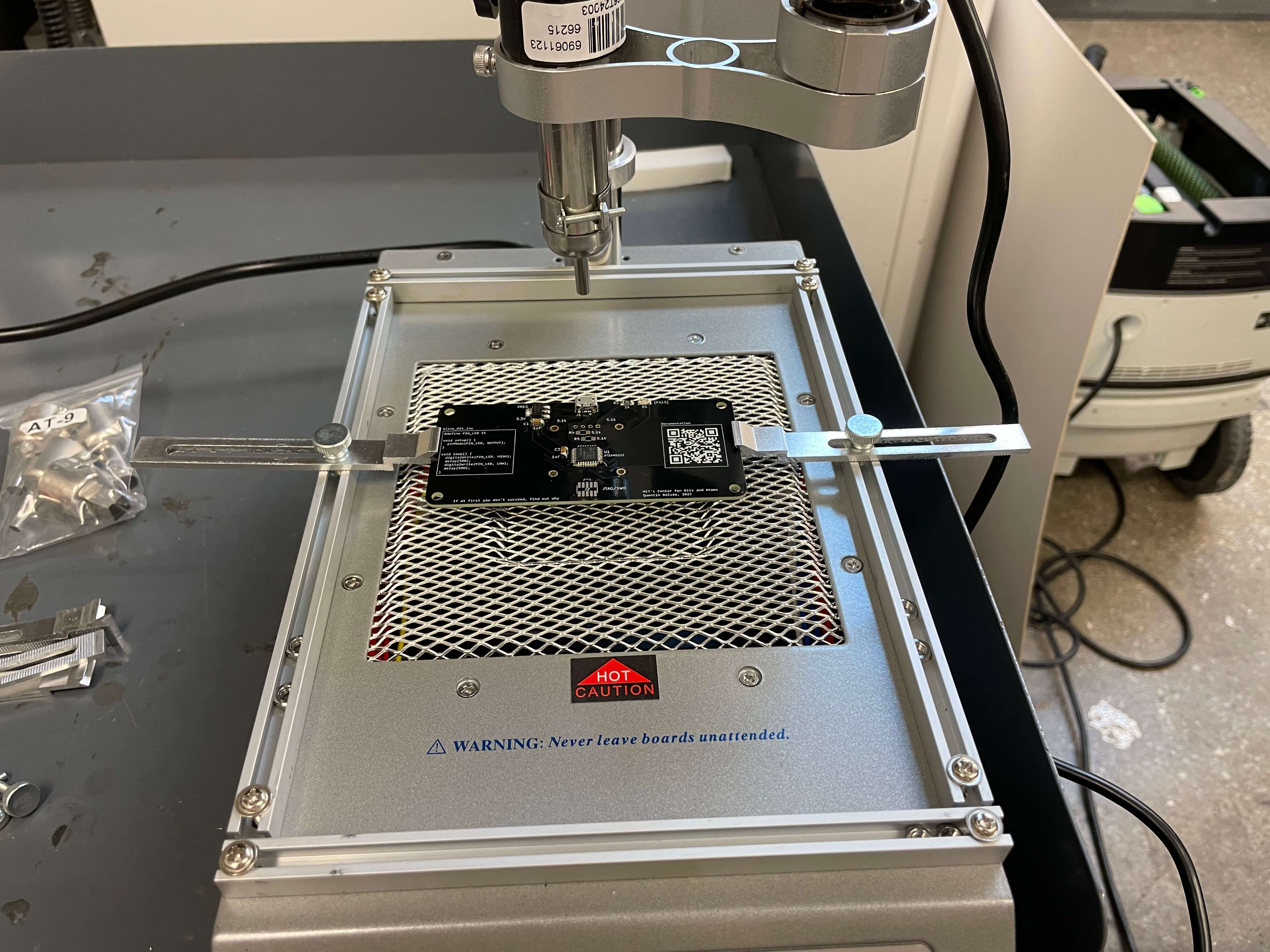
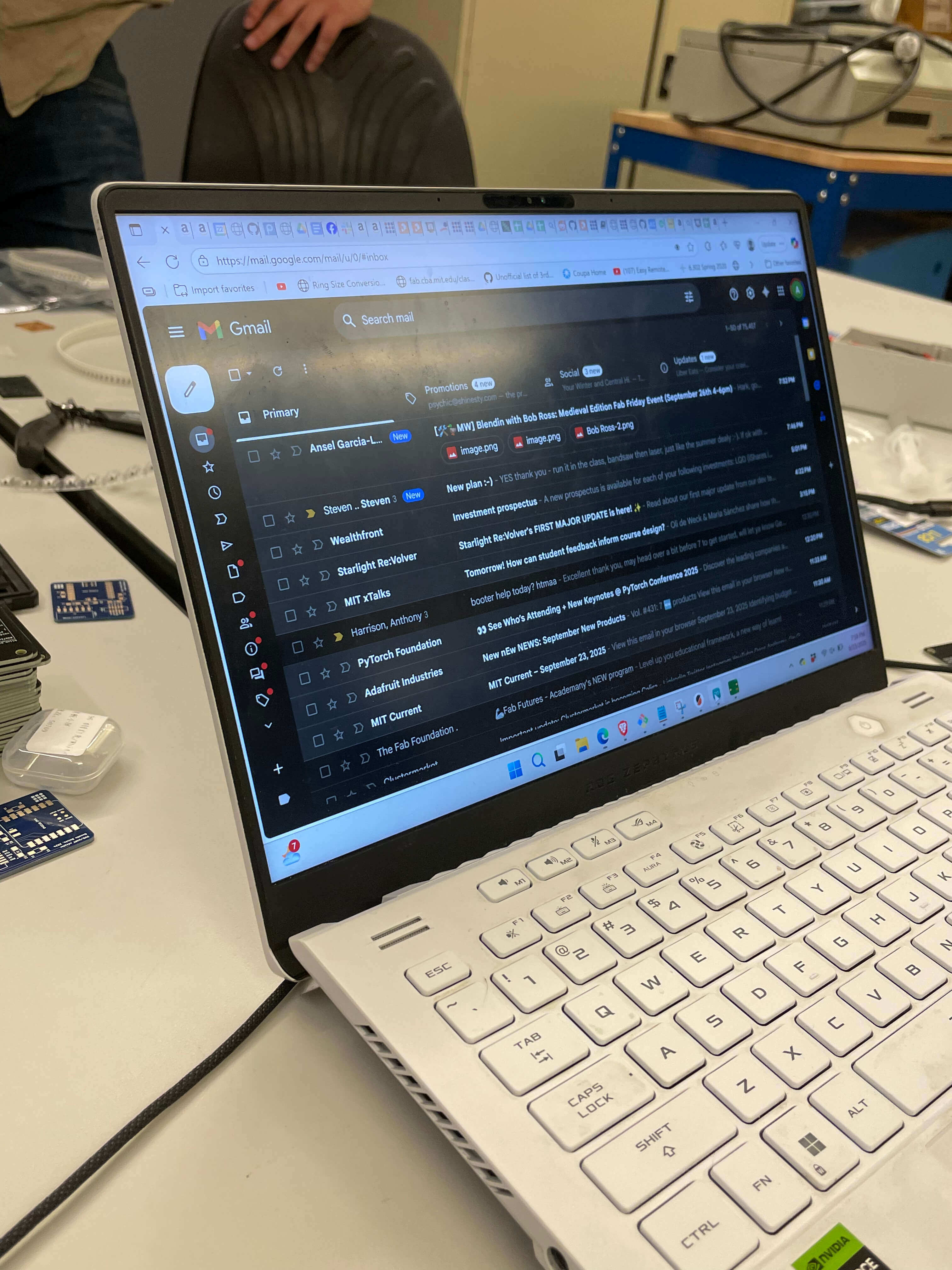
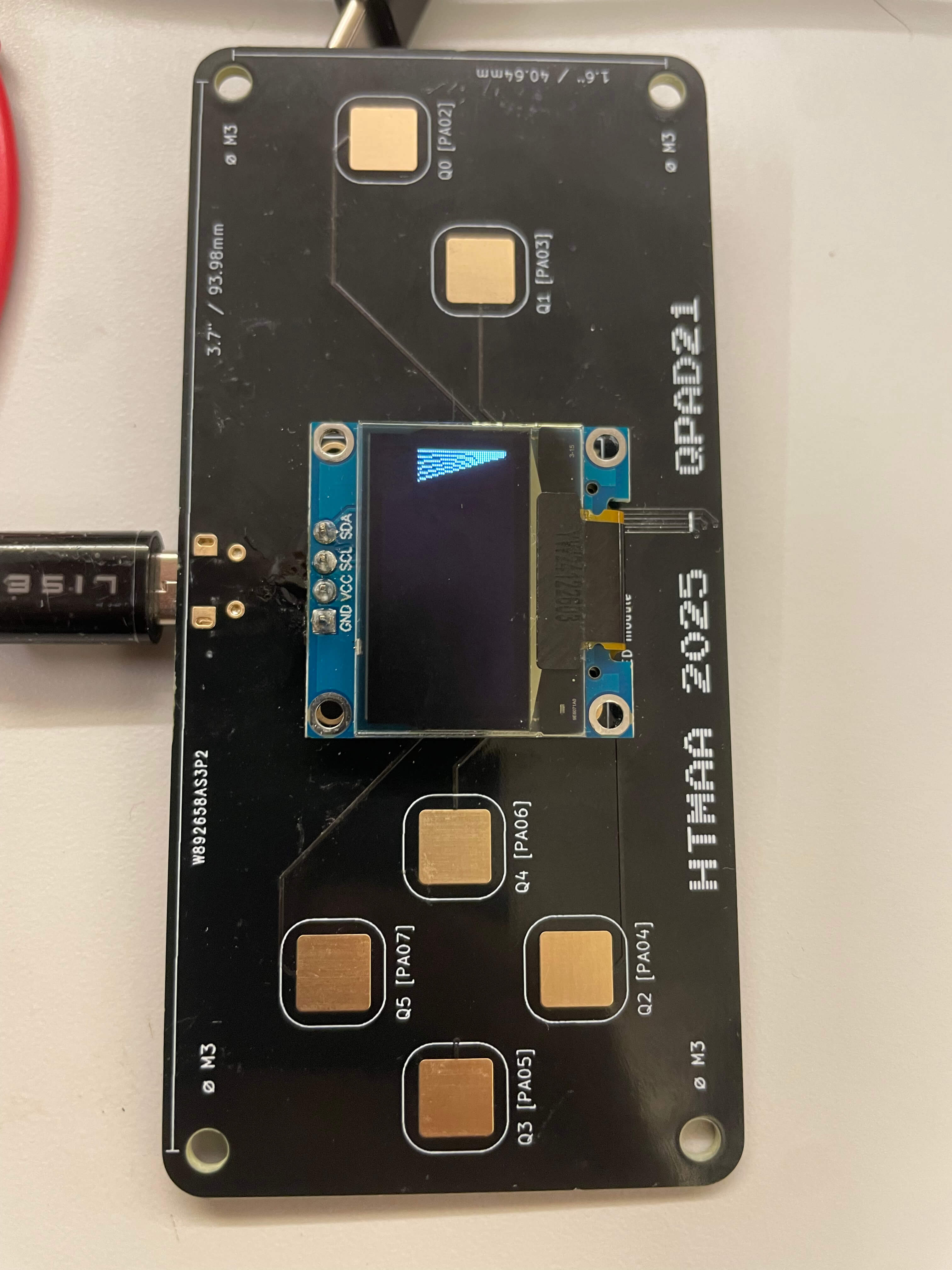
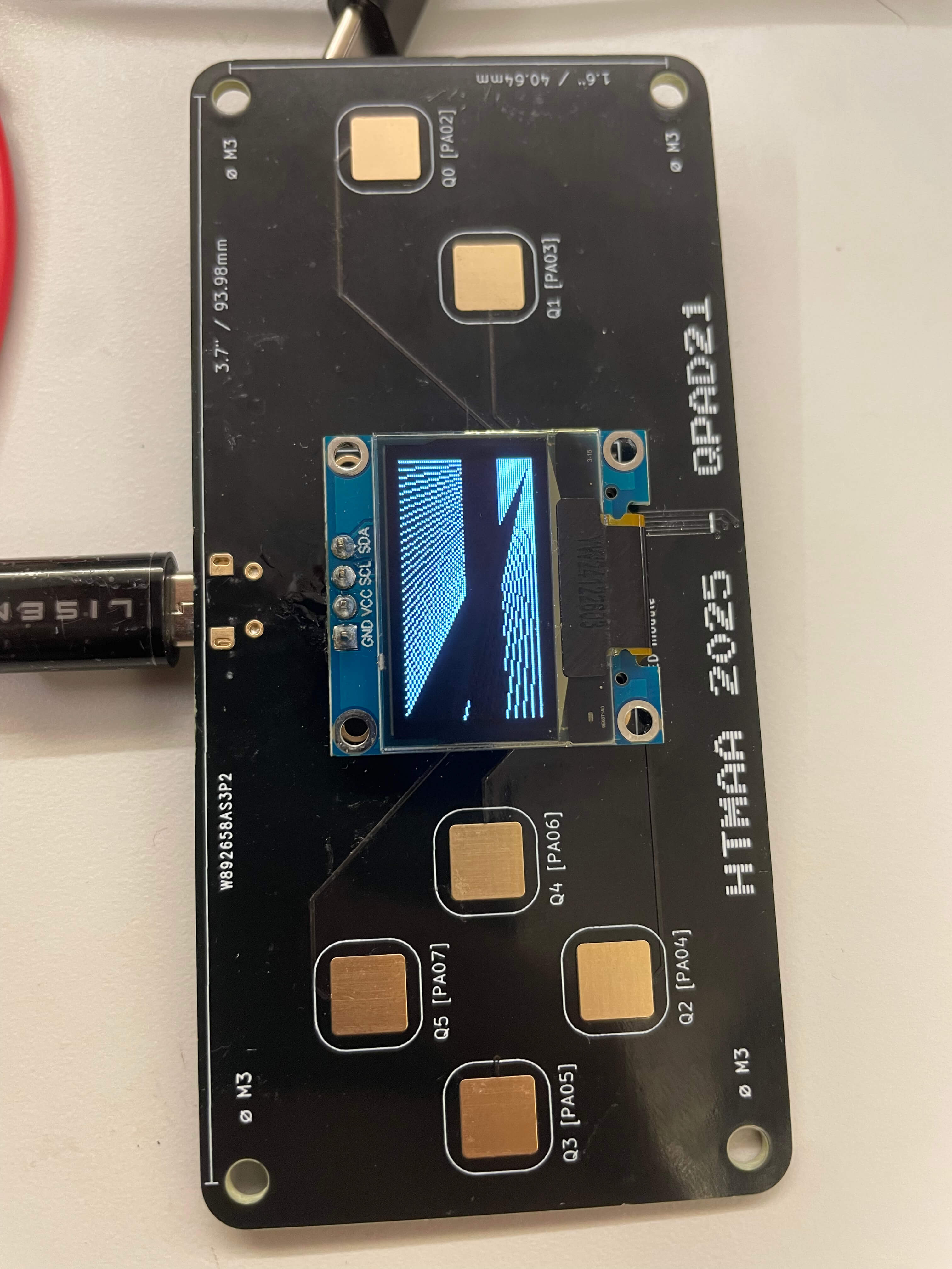
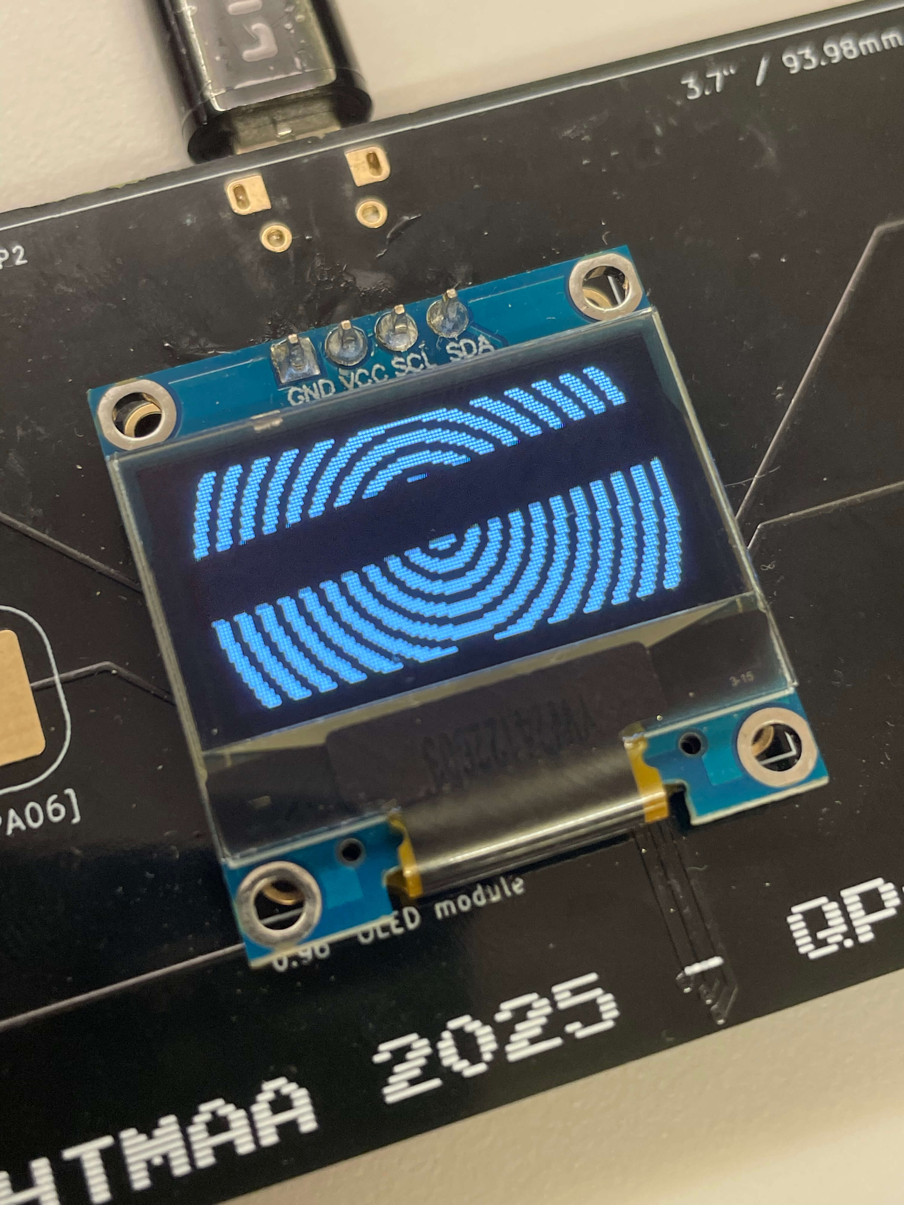
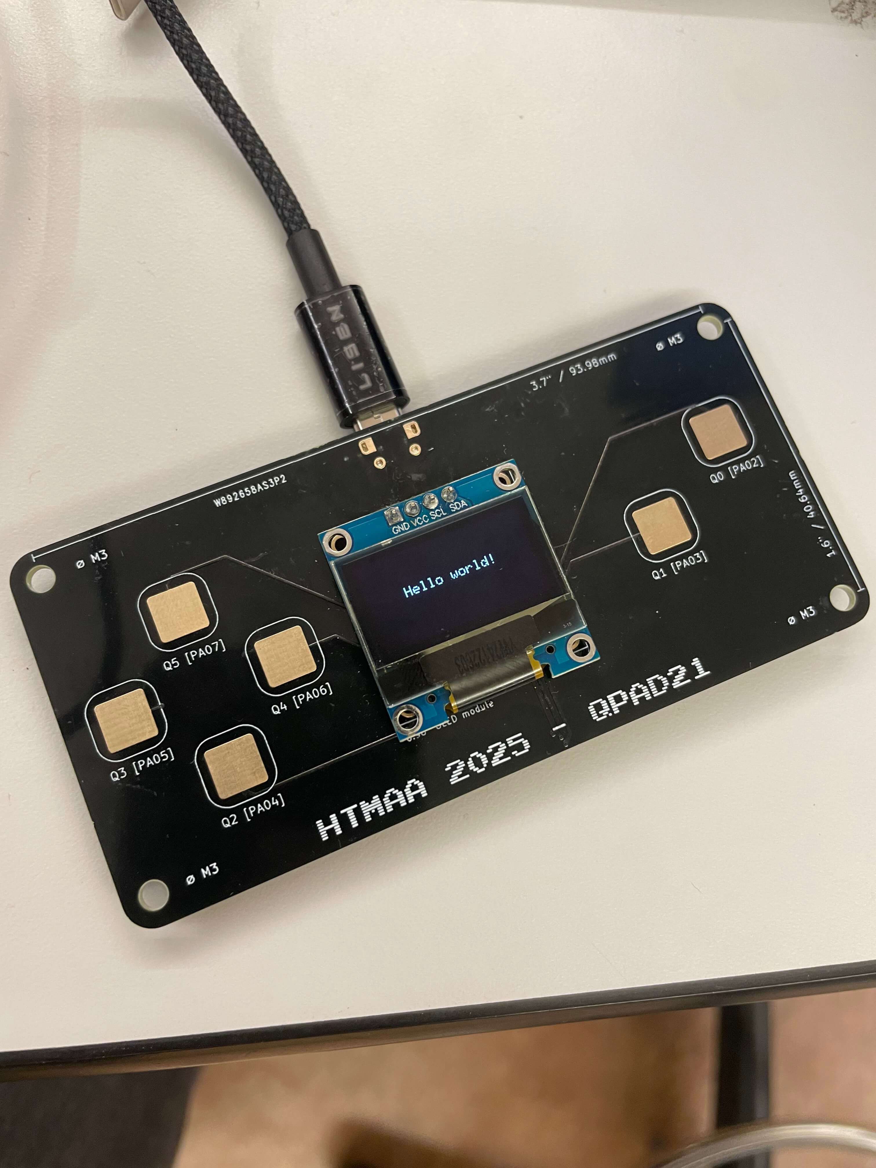
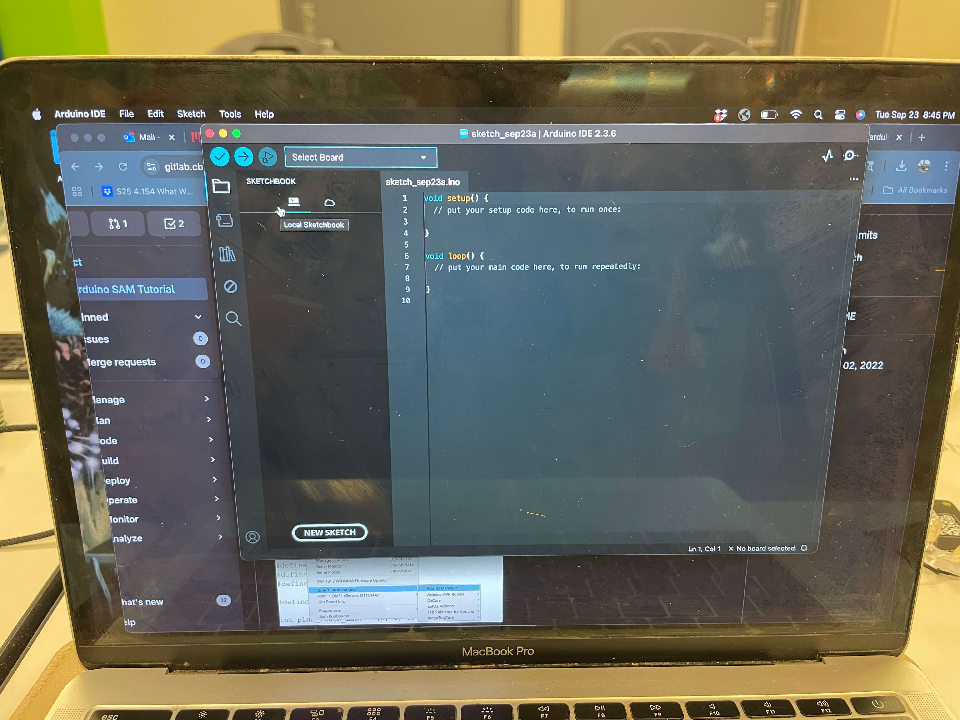
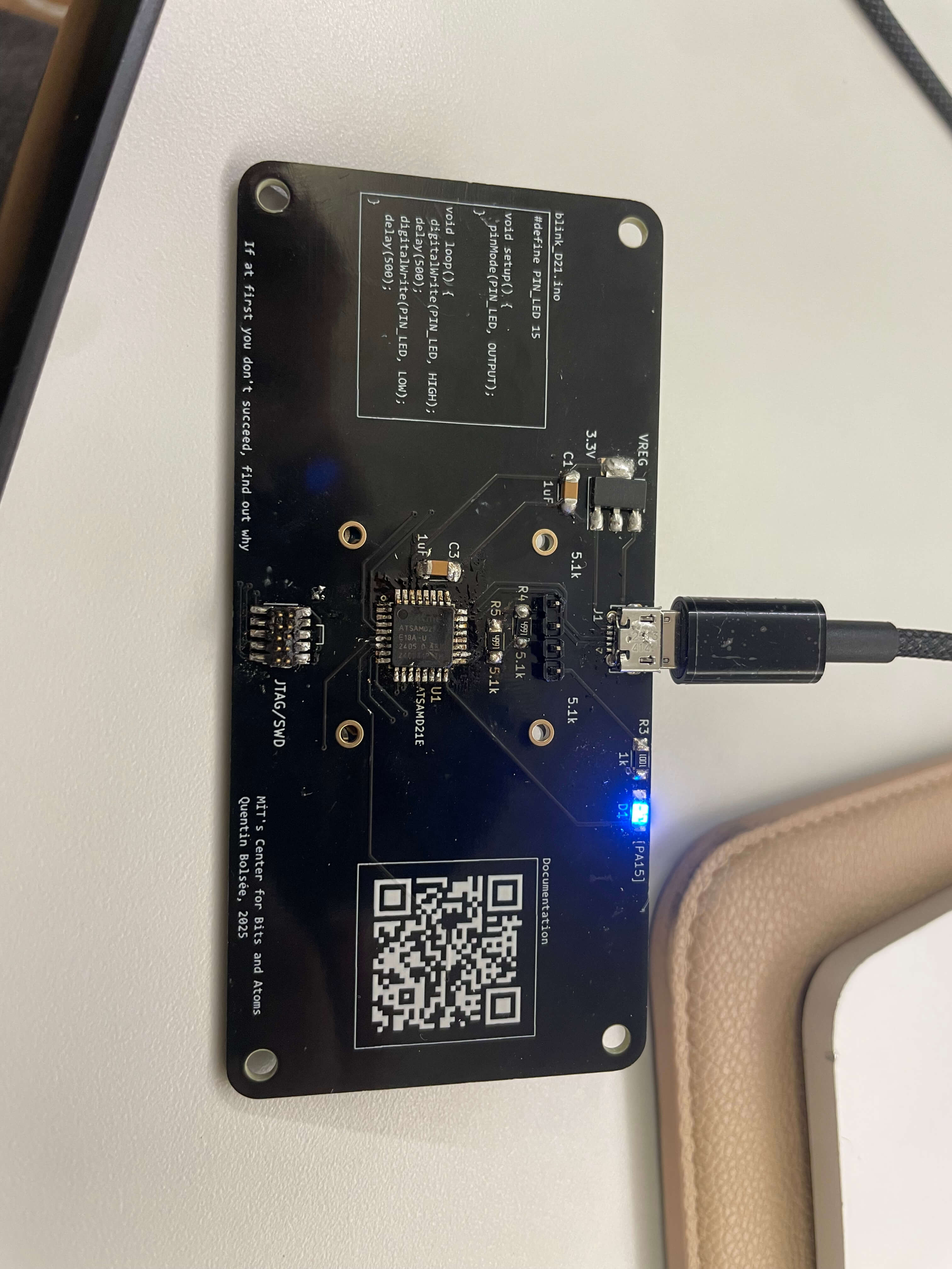
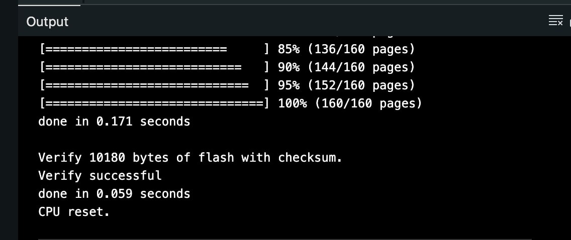
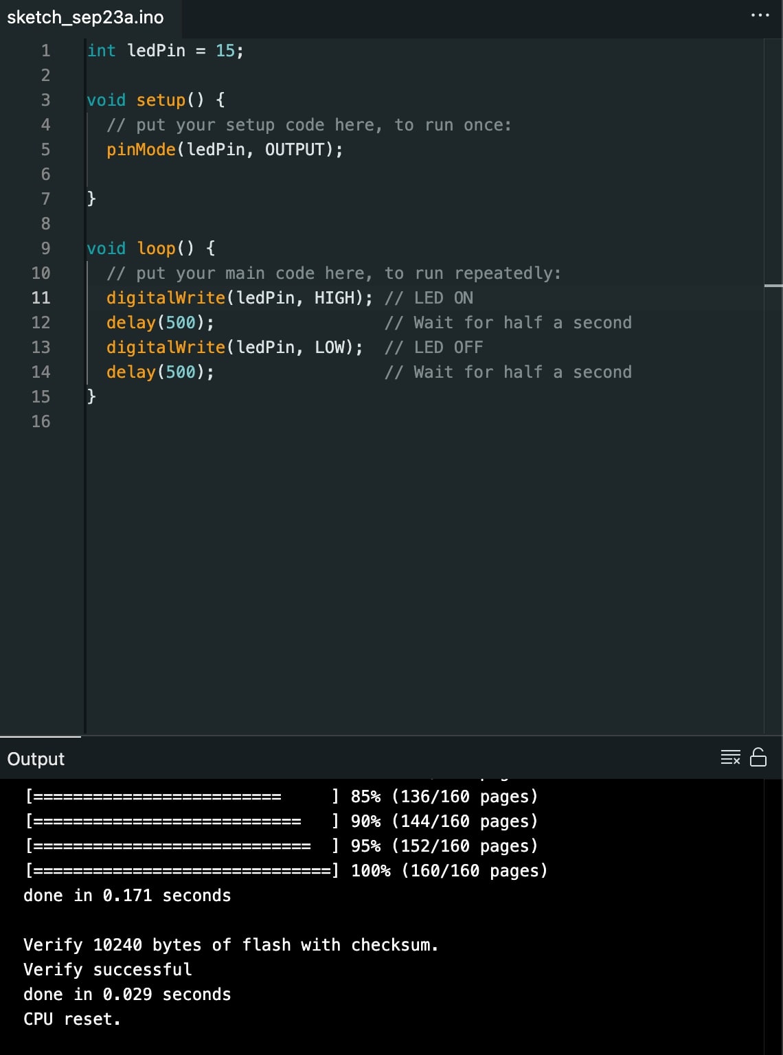
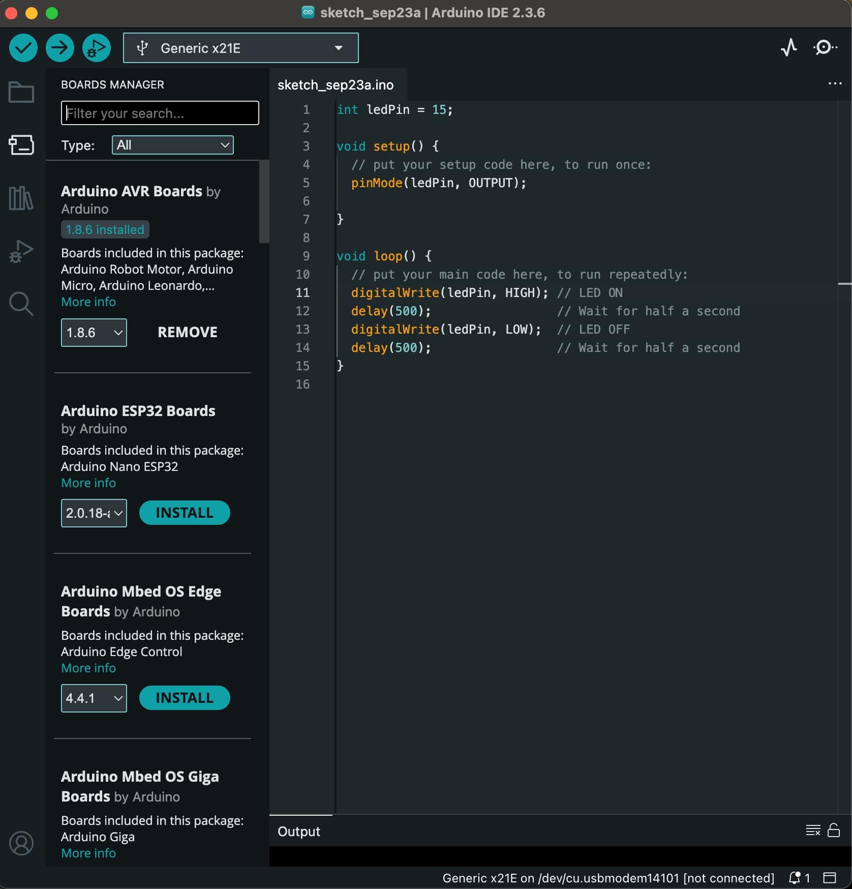
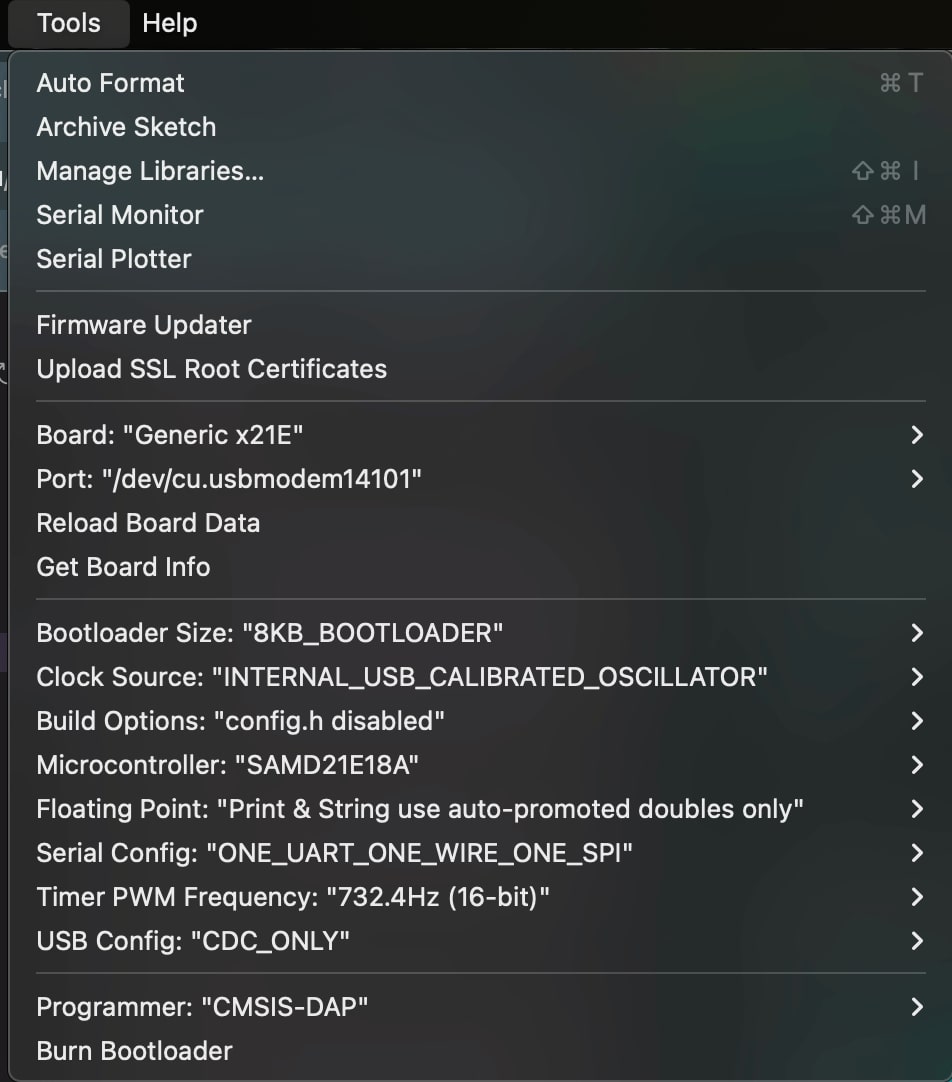
- and yet, it loaded up and passed our tests. We ran a e-meter in a mode where completed circuits would beep to check various areas for shorts and none were found. After this test (fig 39-45) I was able to input code into the microcontroller using arduino ide and a tutoral provided by the TA's on github. I wrote the following code (fig x) using google ai to talk to about the code words I would need to utilize to create a gap and how many of the timing units would equal one second. I then set the settings in Arduino IDE for the microcontroller and the programmer (fig x) and uloaded it, and it worked on the first try (fig x-x). I lucked out.