Week 6
Assignments: Electronics Production
group assignment:
• characterize the design rules for your in-house PCB production process
• submit a PCB design to a board house
individual assignment:
• make and test an embedded microcontroller system that you designed
PCB Production
print file is here: file
code text file is here:file
Pale Blue Dot
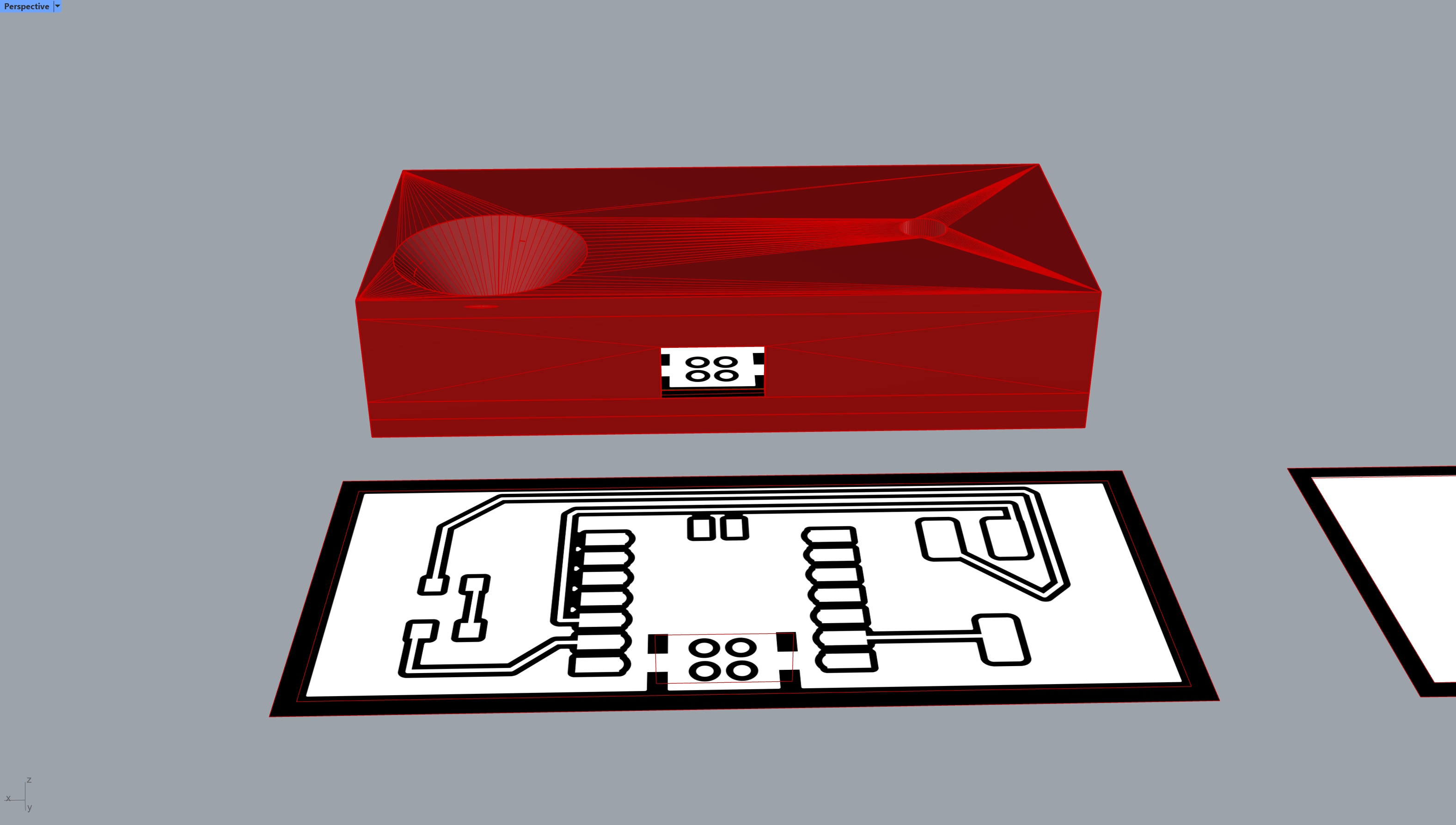
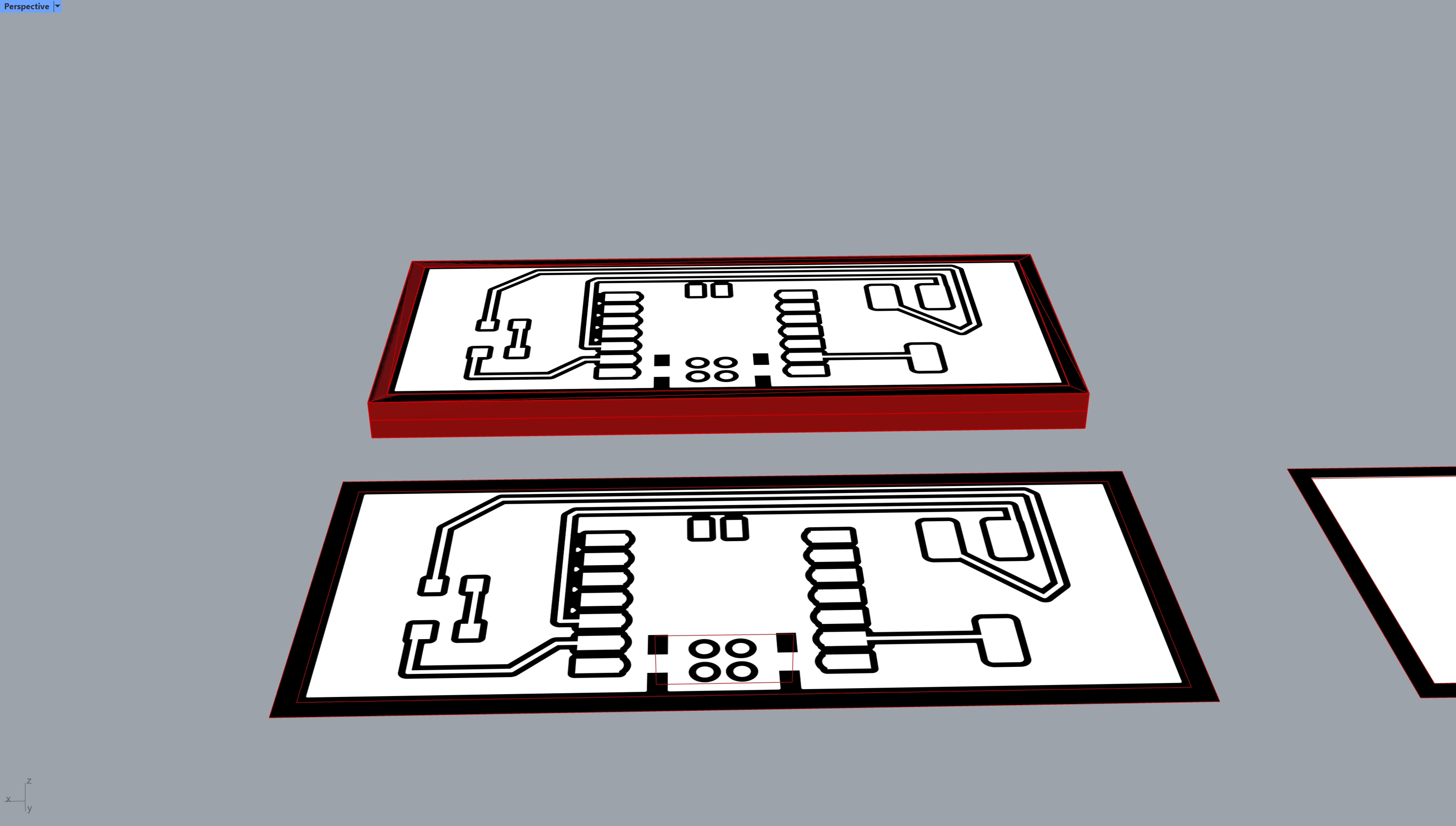
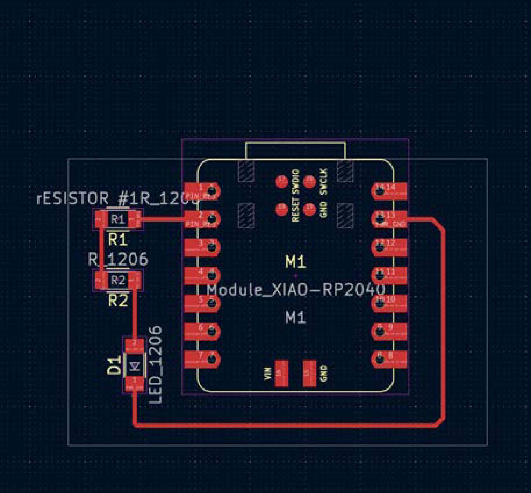
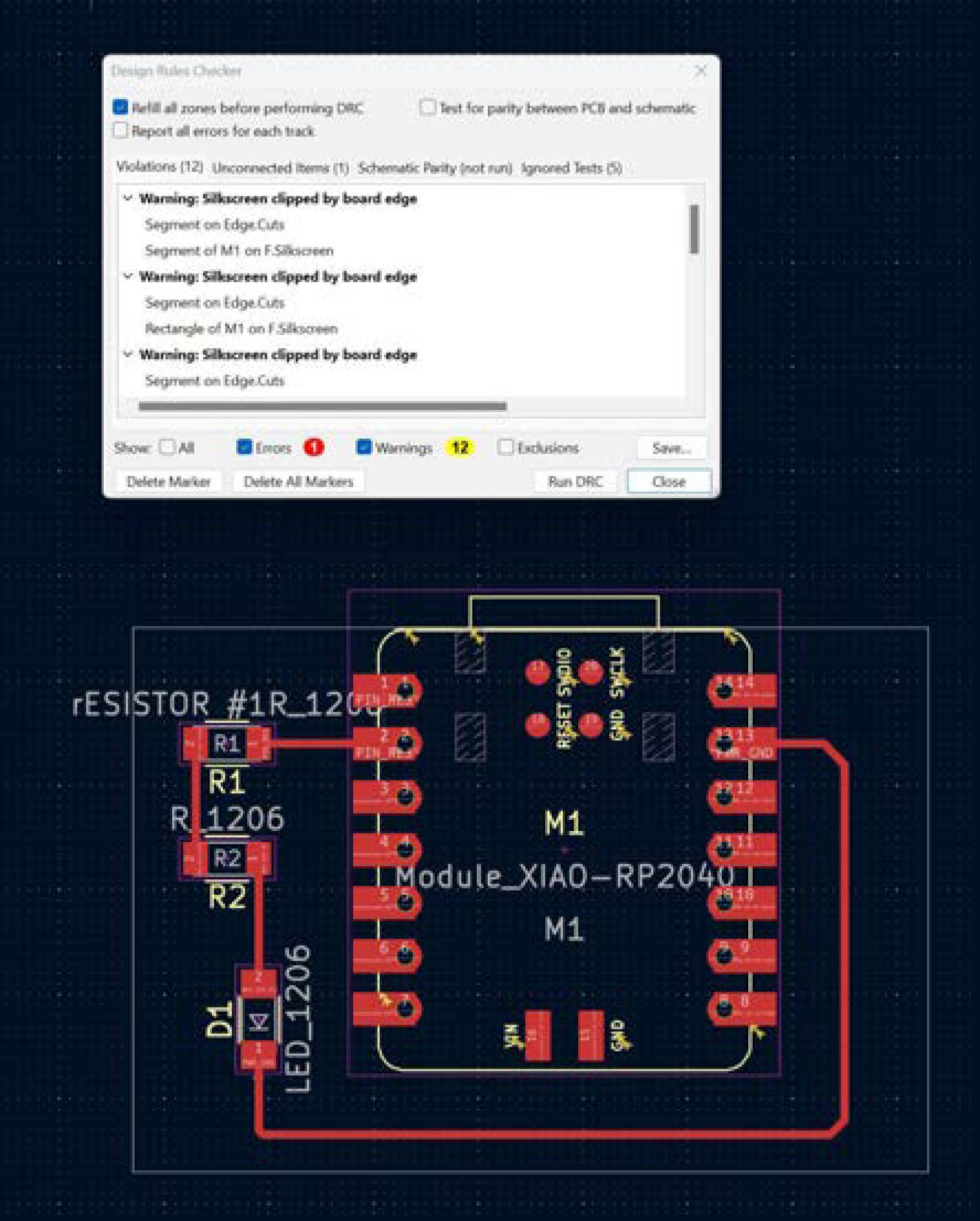
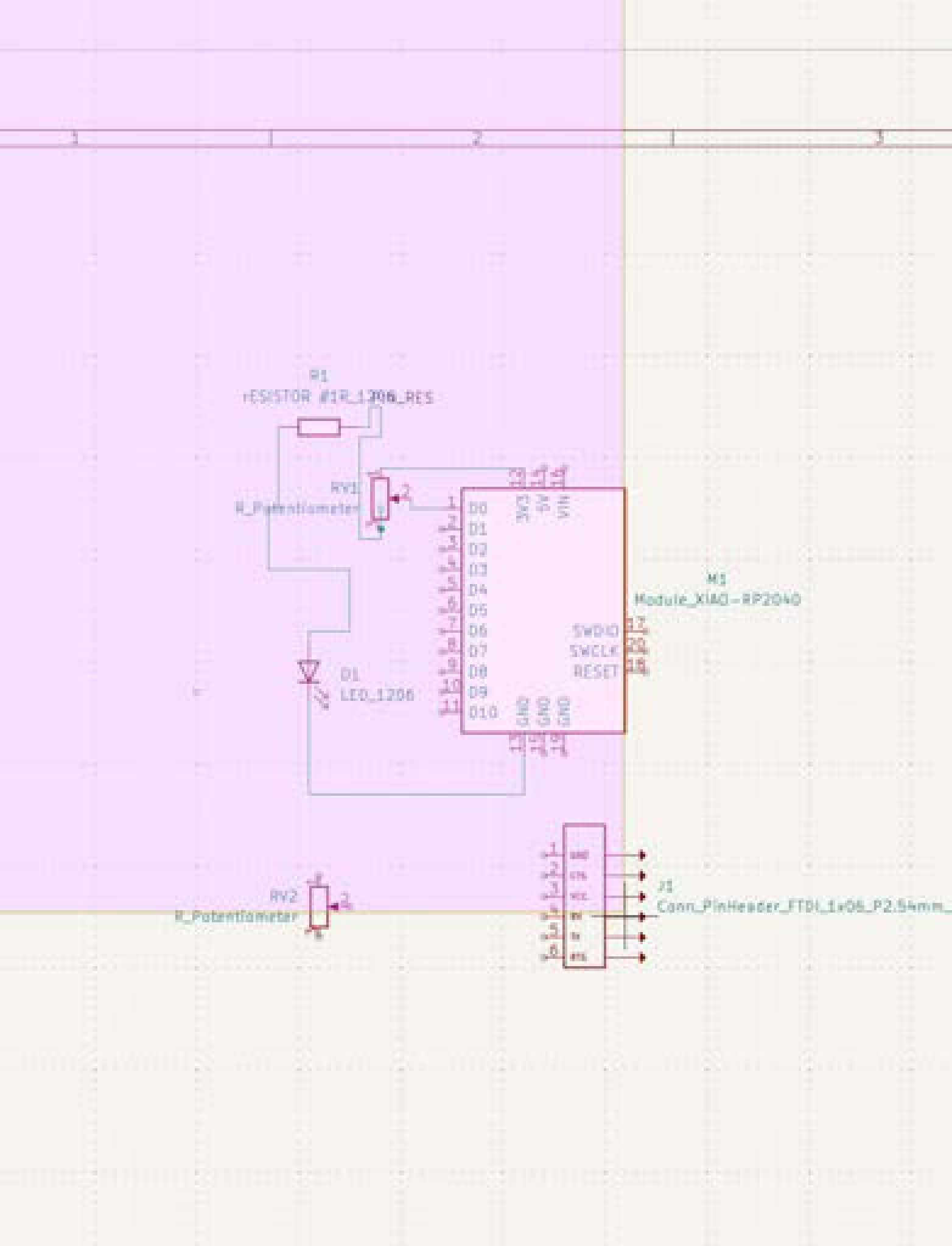
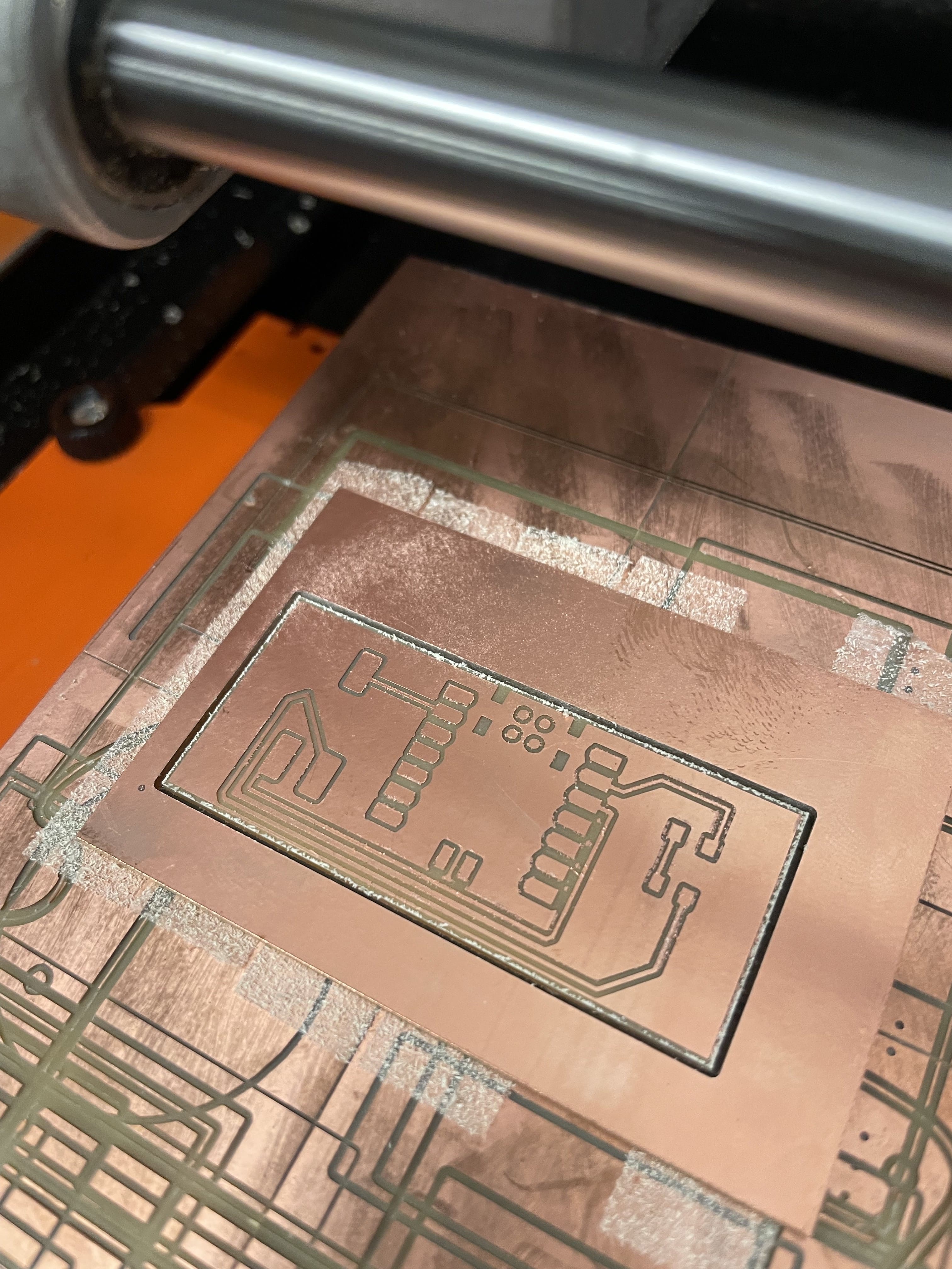
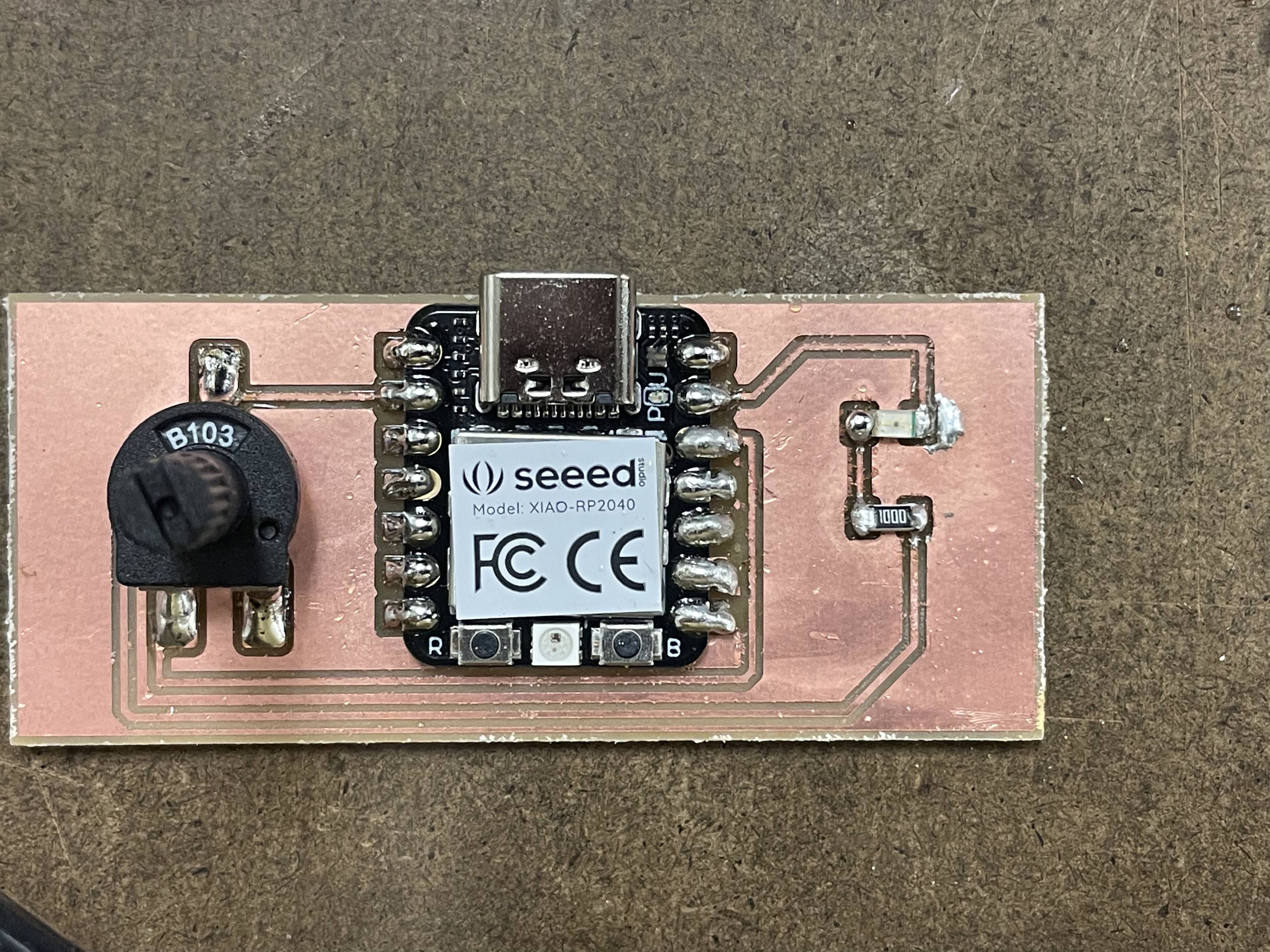
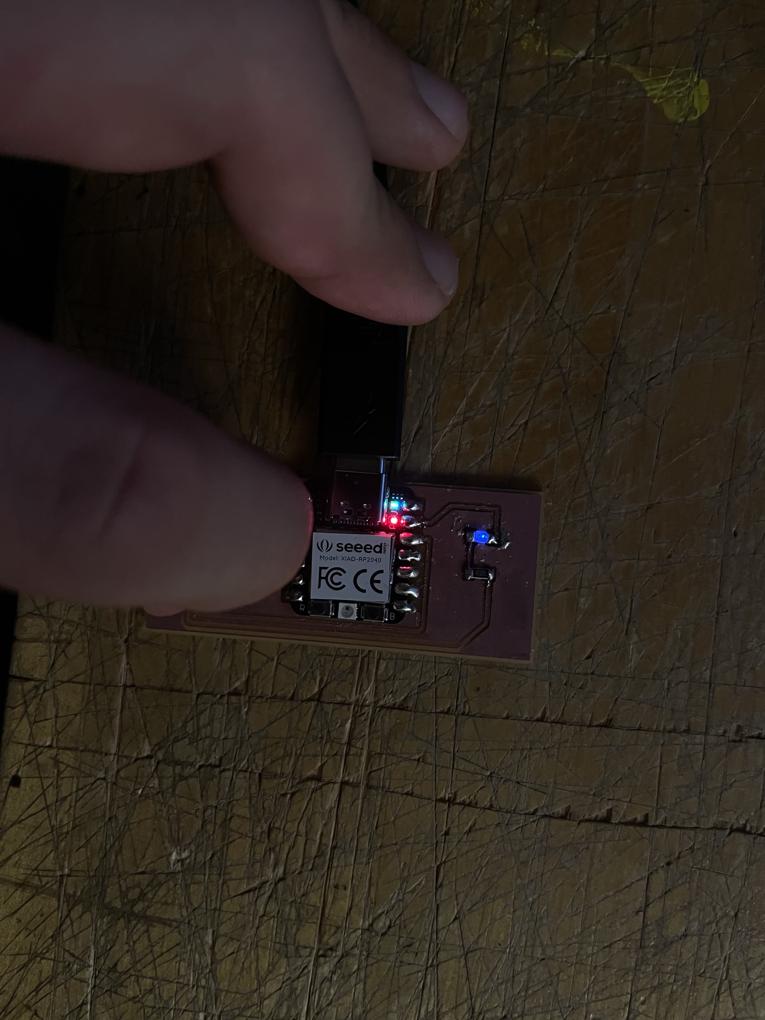
My PCB design is a simple circuit using one data pin, a potentiometer, a single resistor, and a single led. The circuit passes through these components in this order, from data pin D1 through the 2nd Pin in the Potentiometer, and then another trace extends from 3v3 power through pin 1 on the potentiometer, then through a 100 ohm resistor that I calculated was appropriate for my 1206 Blue LED. The PCB trace and cutout milling files are fig1-2 respectively. Progress images of my Kicad use (fig 3-8) show the progression towards the circuit described above.


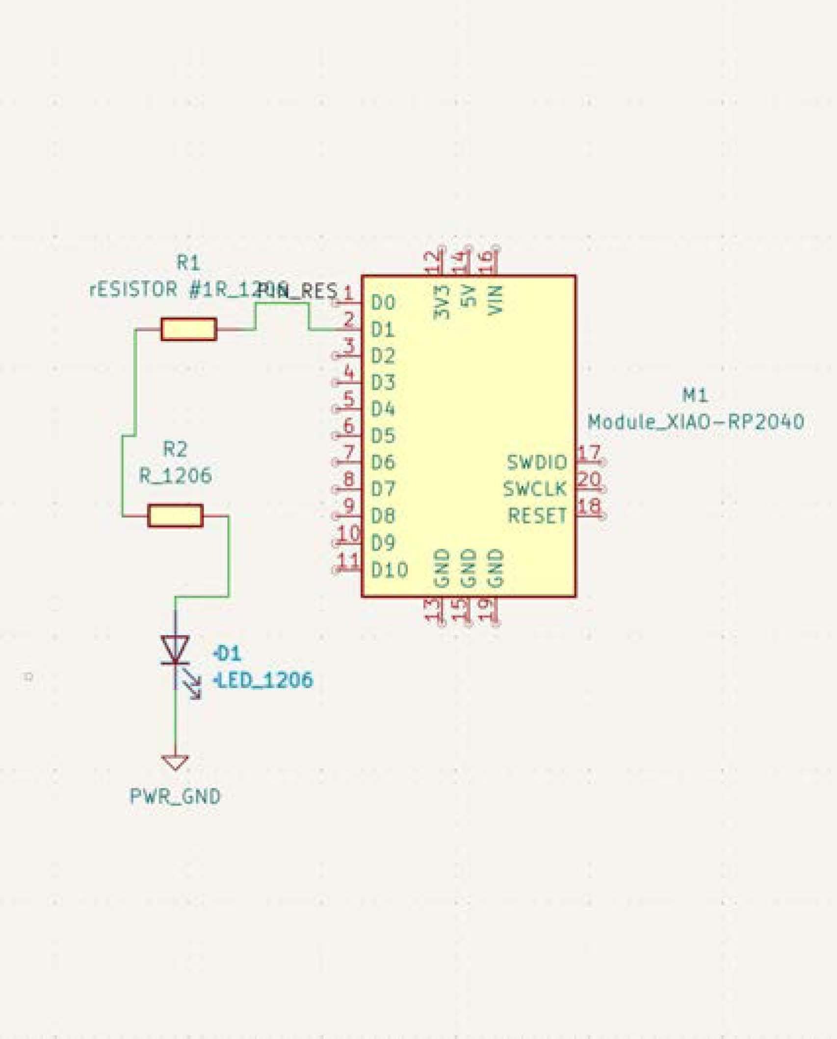
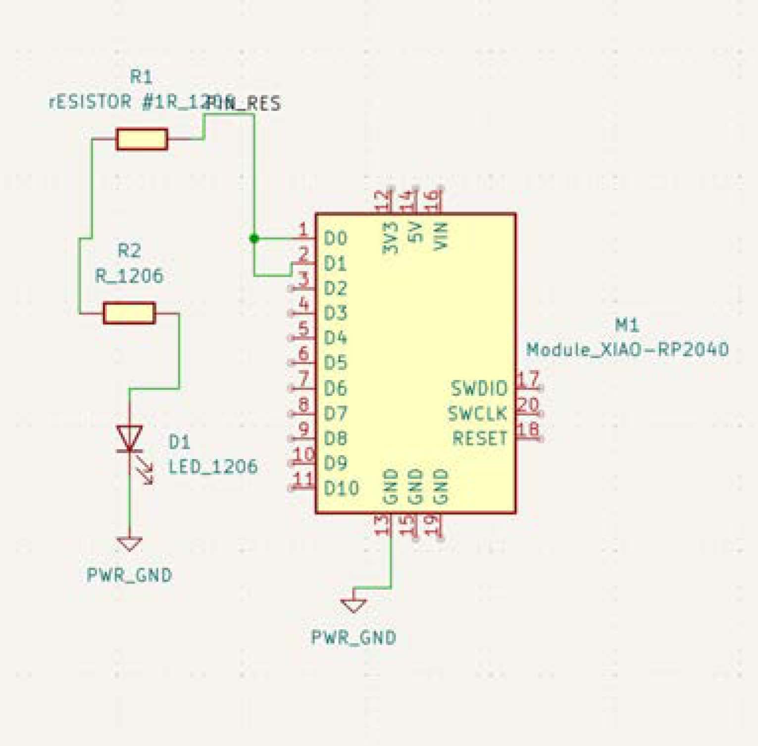
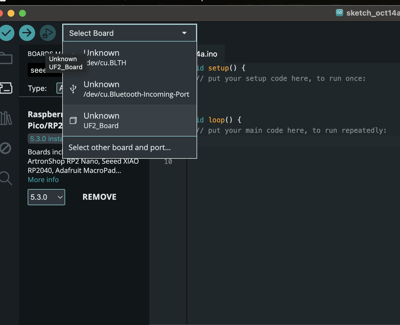
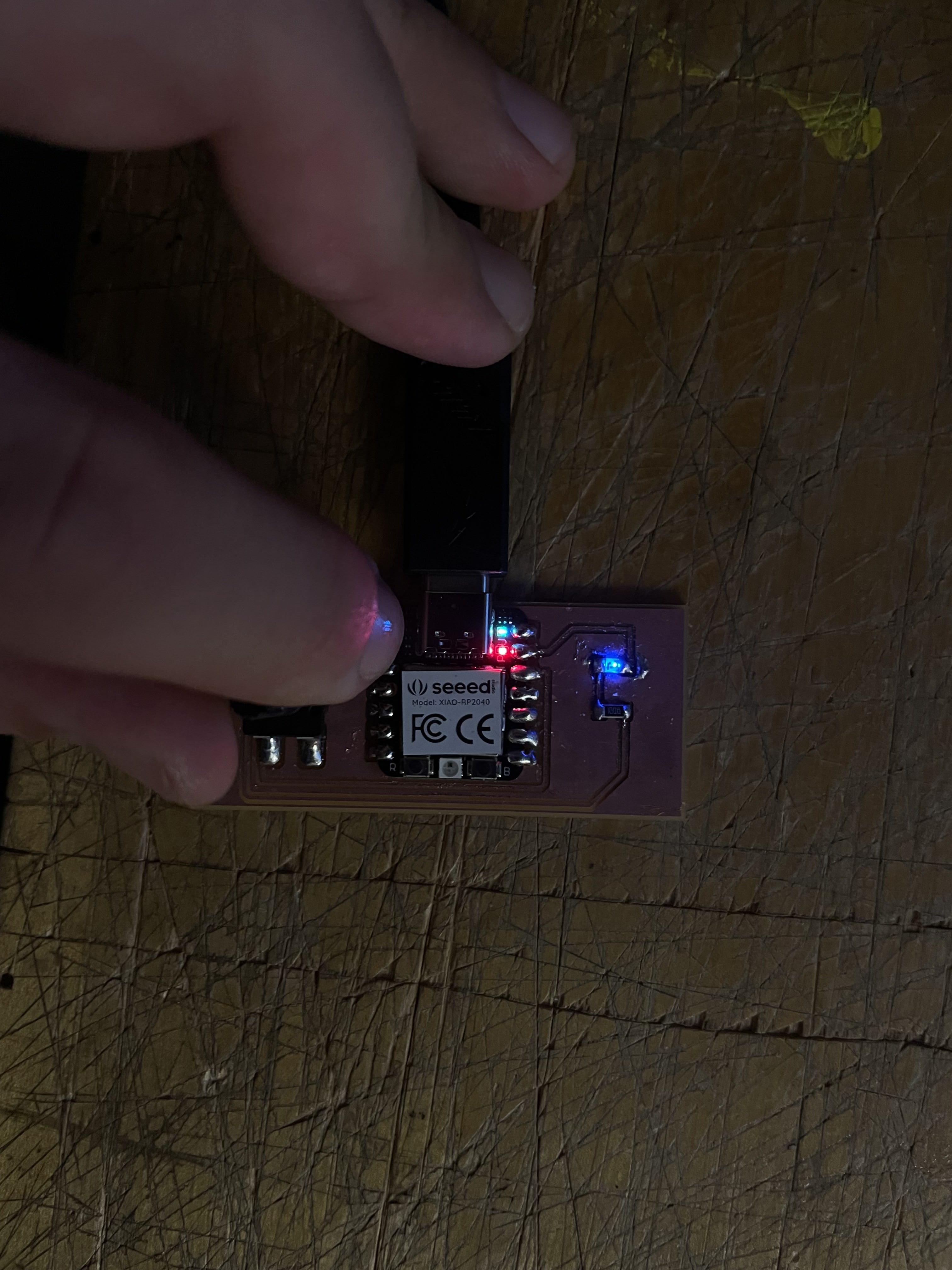
The pcb package is meant to allow for the dimming of a controlled led. To prove the funtionality of the code via D1 data pin, I wrote code to time out morse code that could strobe a yoko ono / anohni song called "I love you earth".
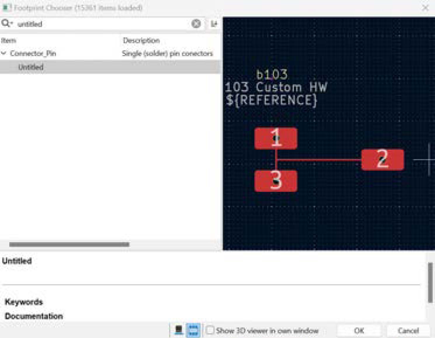
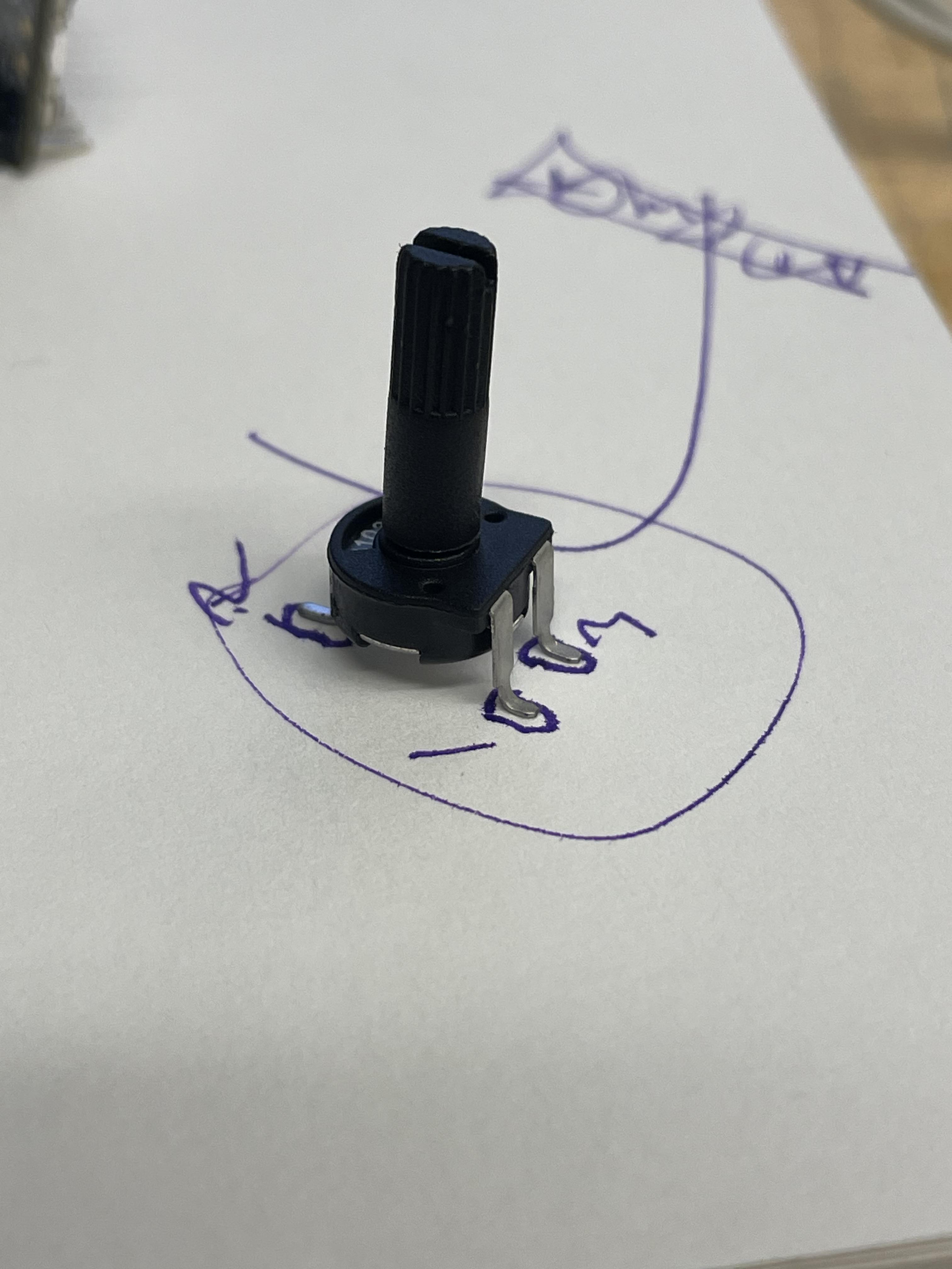
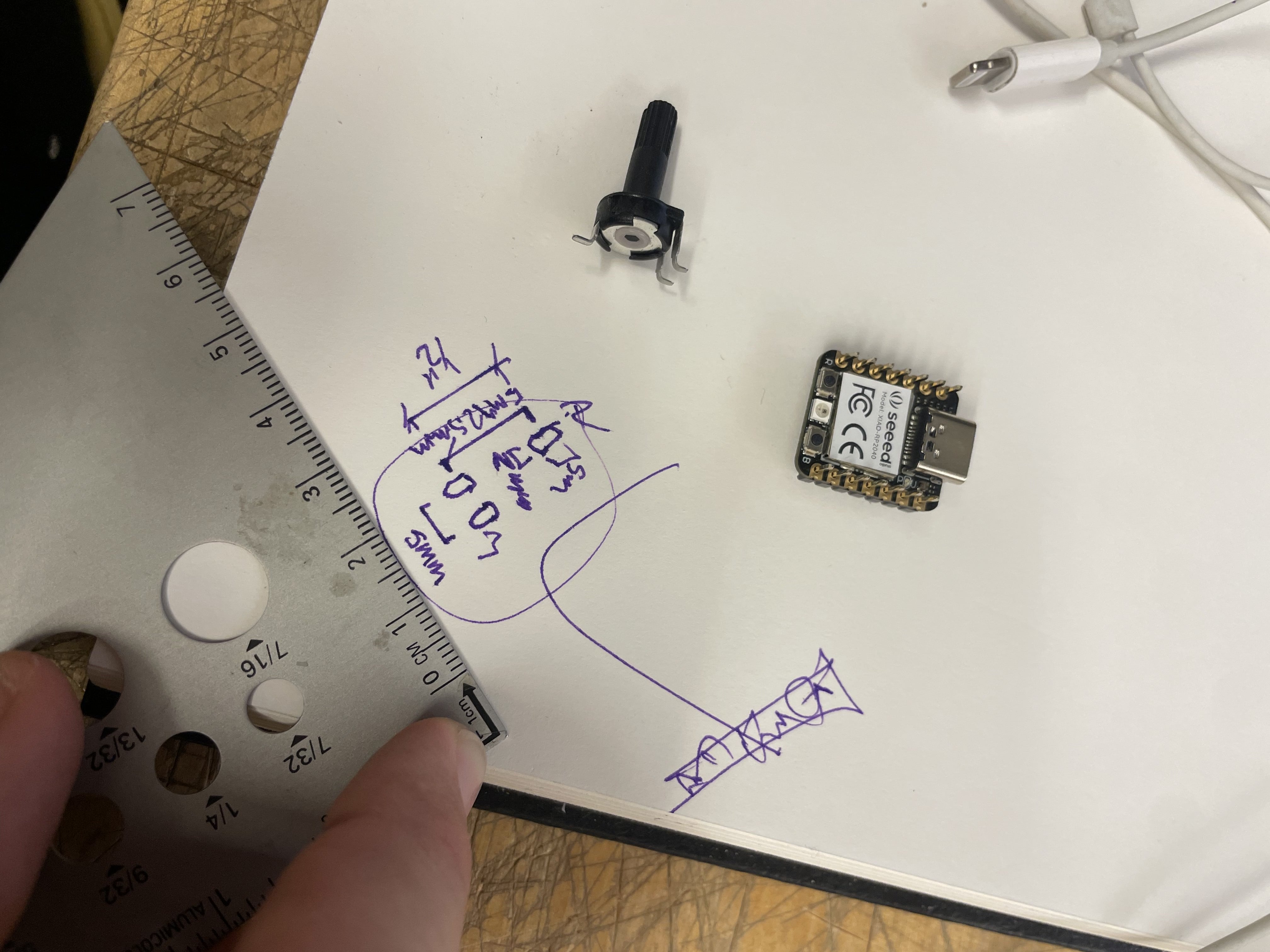
The potentiometer I found in the shop that I liked was not listed in our fab library so I was prompted to lay out my own footprint and place it in the pcb editor. To make the pads line up I just traced the component and its little legs that I bent so it sits flat, and measured the size of the pads and the distances between the center points of each and made the following component (fig 9).
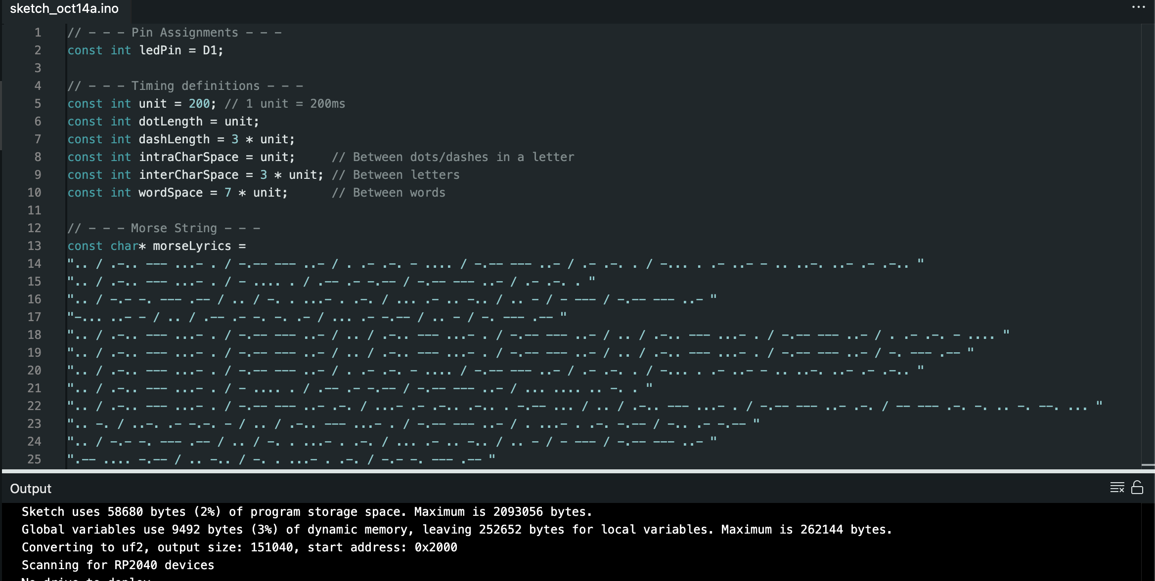
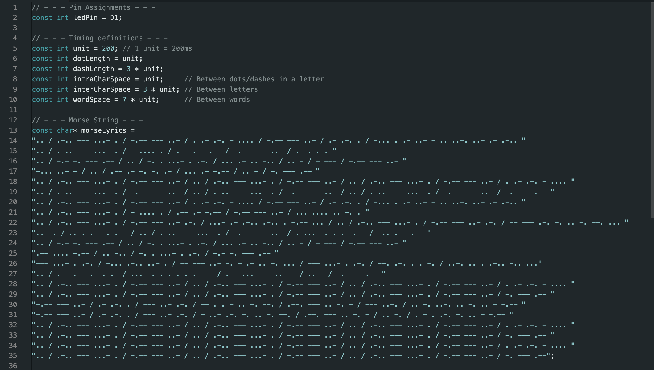
This is the code I wrote with prompting help from AI.
• I asked AI to write me the Morse Code String for the song lyrics that I gave it.
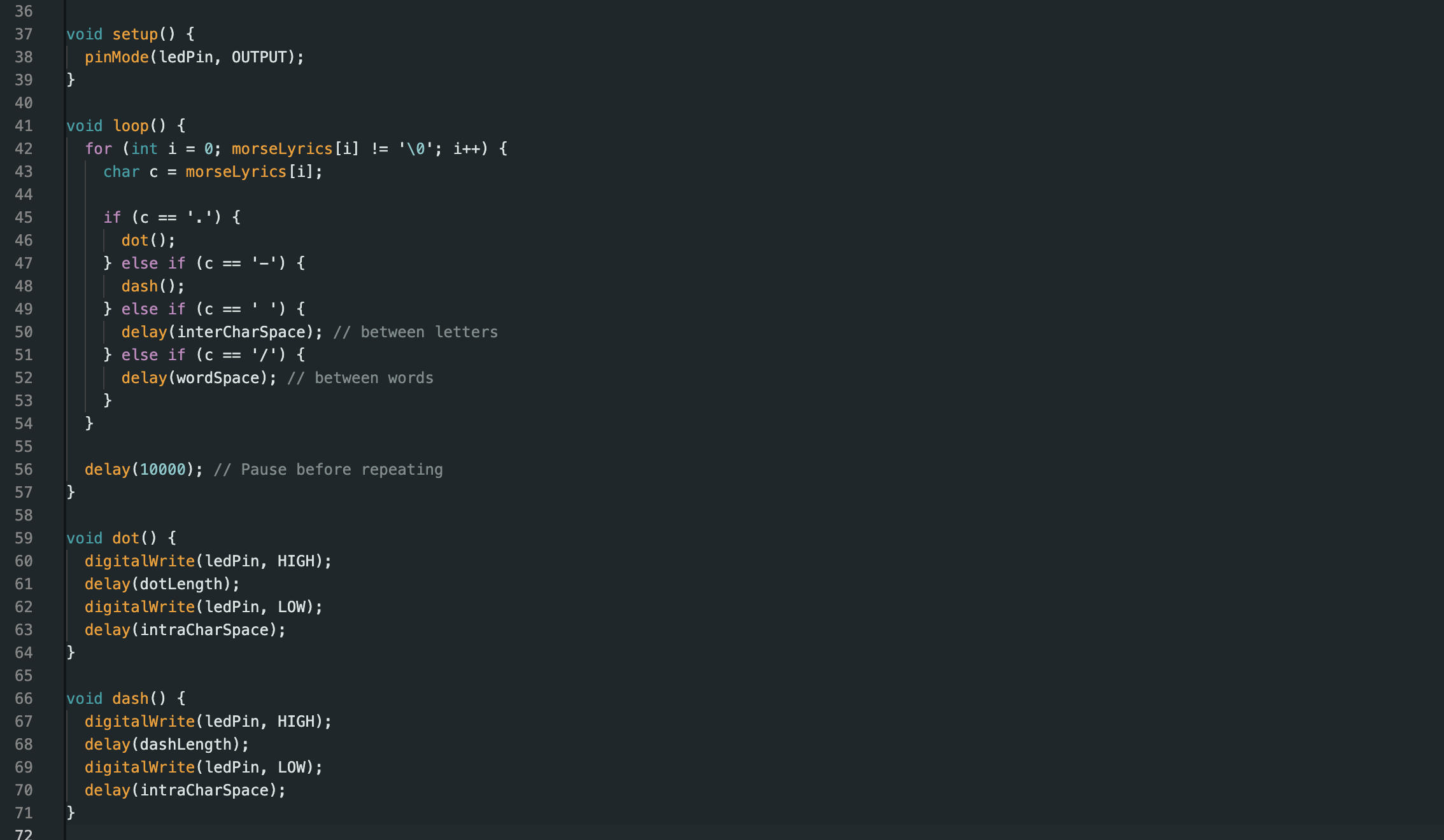
• I asked AI for the code words to set time, duration, and how to lay out the logic for and if, else if, else if, else if condition for the four types of letters.
• I dont know how long the actual song takes but its several minutes, and at the end theres a 10,000 x 200ms pause before restarting.
• The potentiometer I found labeled B103 had uncertain range of resistance, but after installing and inputing the code, it turned out to work pretty well within the operational range of the 1206 LED.
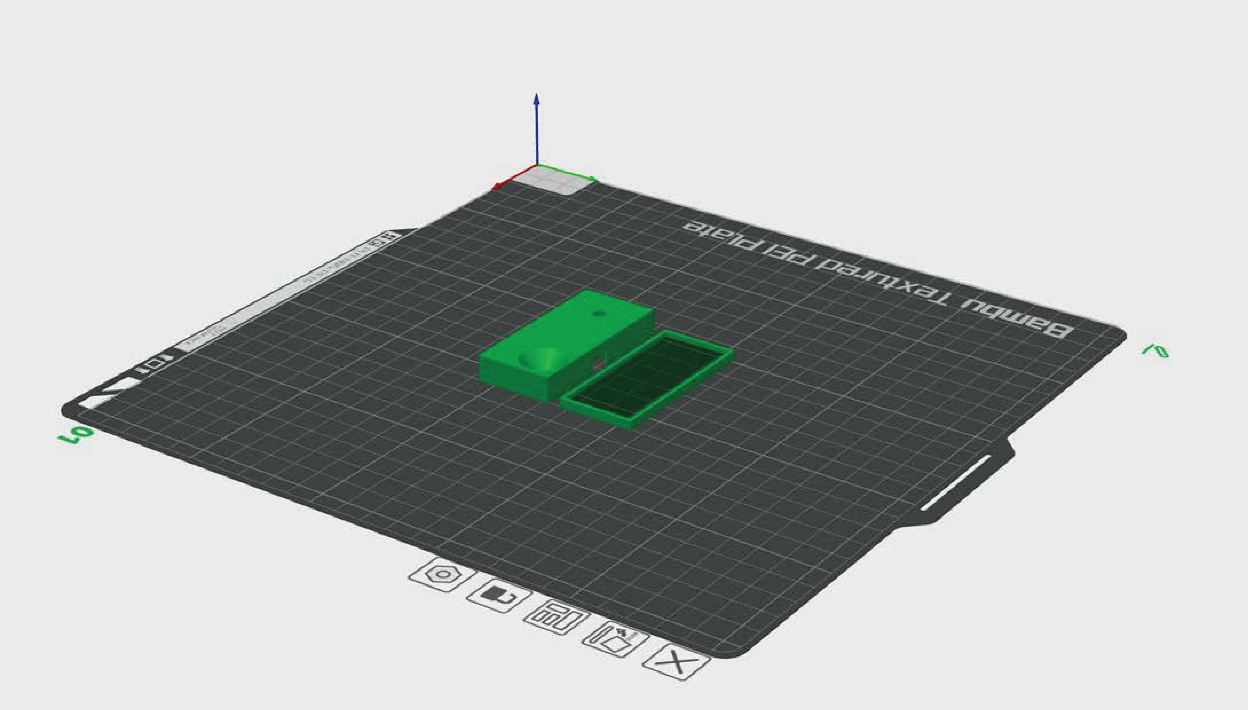
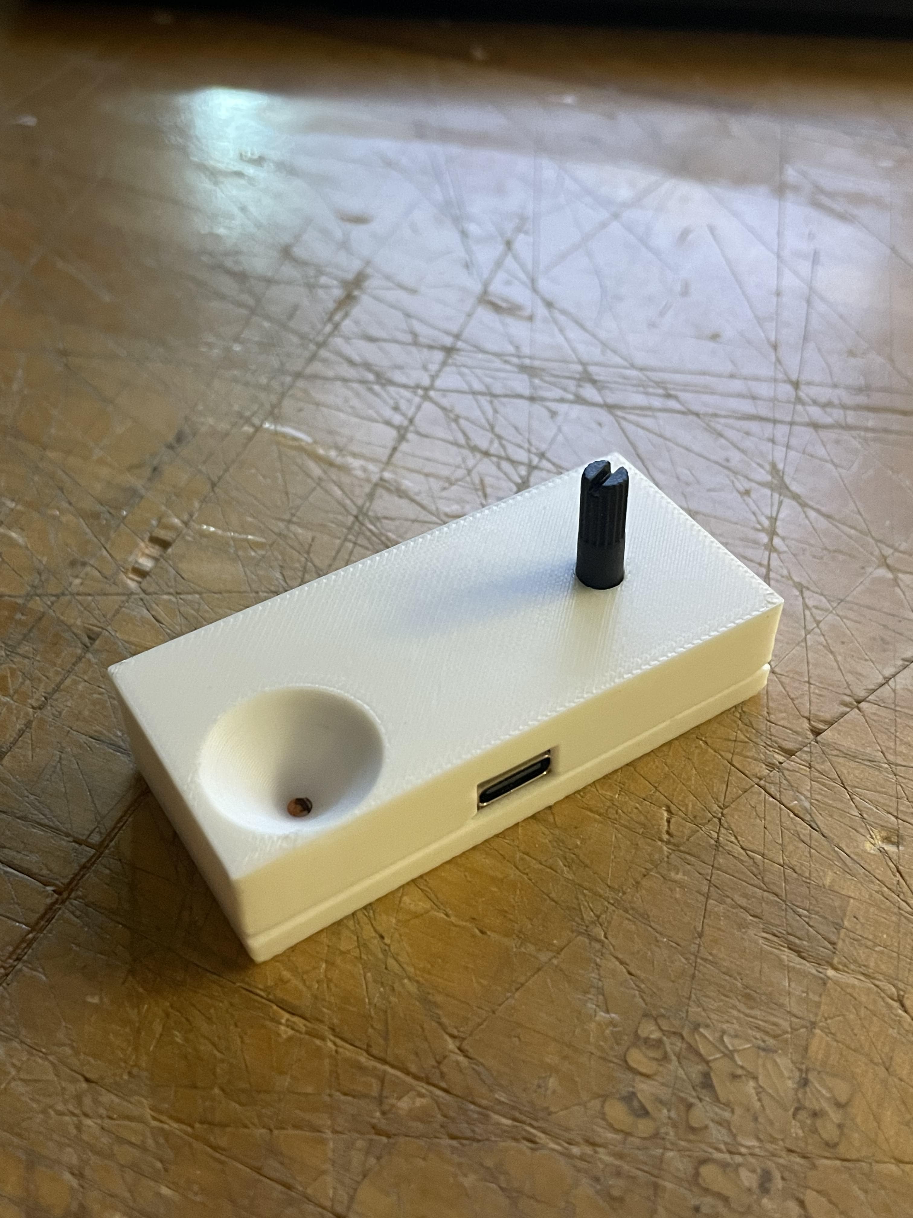
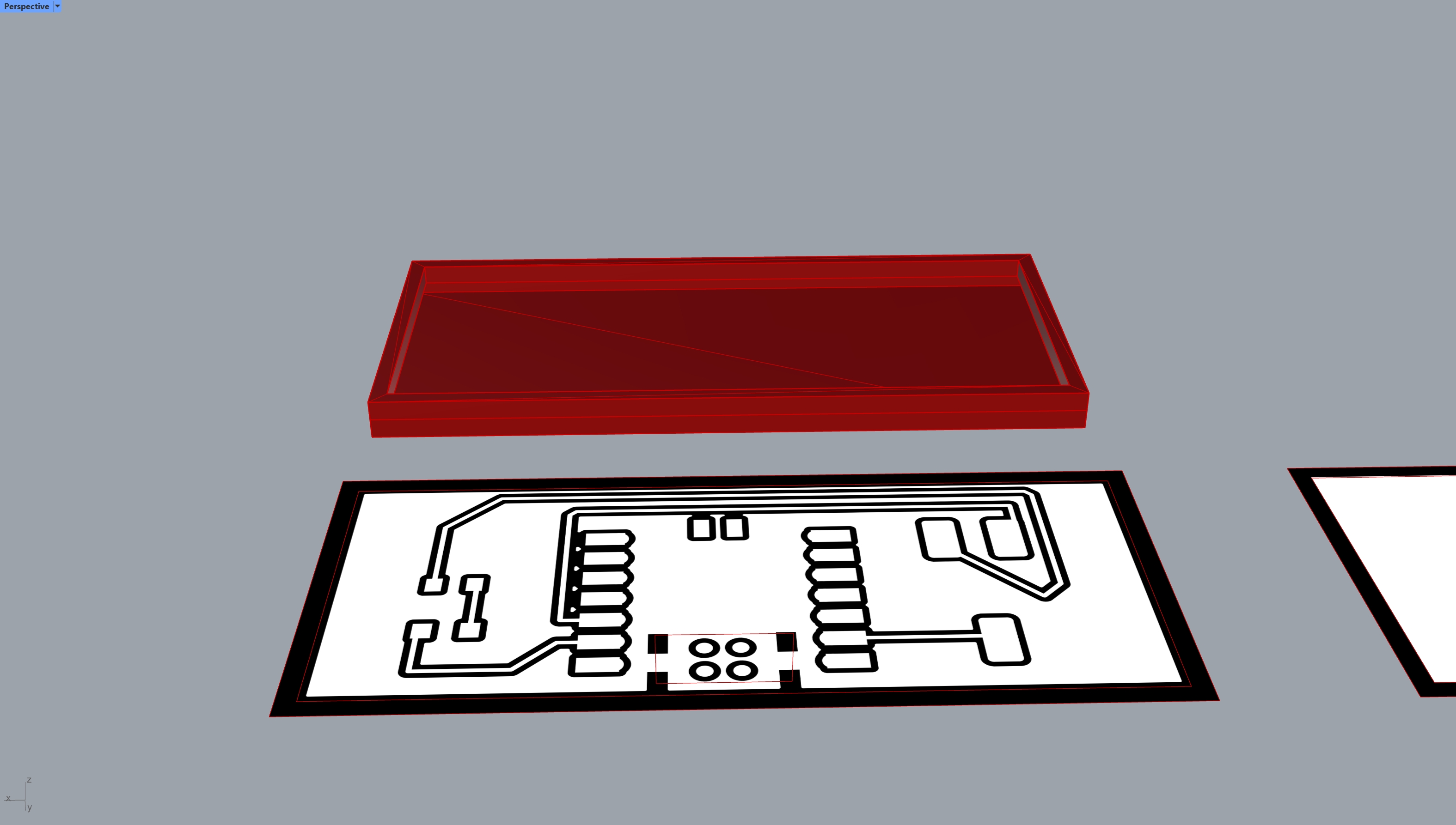
• To celebrate I 3D printed a housing.