How To Make Something Big!!!
Introduction
This assignment needs to learn the CAM (Computer-aided manufacturing) and CNC (Computer Numerical Control) to make something big. I want to take this chance and make a stargazing chair, which is relevant to my final project, and this could be my prototype of its mechanical design. I explored more online examples of making a wooden binocular chair. Finally, this one interested me, and it can be designed as a wooden joint structure without using any glue or screws:
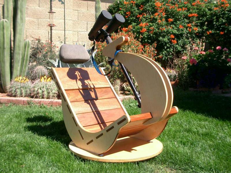
The function of this chair should be two-axis rotatable, so I bought a Lazy Susan turntable bearing; the 20-inch commercial model can support up to 160 kg, so it can work as a basement. For the tilt rotation, I use the rocking chair structure as a wheel, and I also designed two simple tracks to limit it.
1) CAD of Stargazing chair:
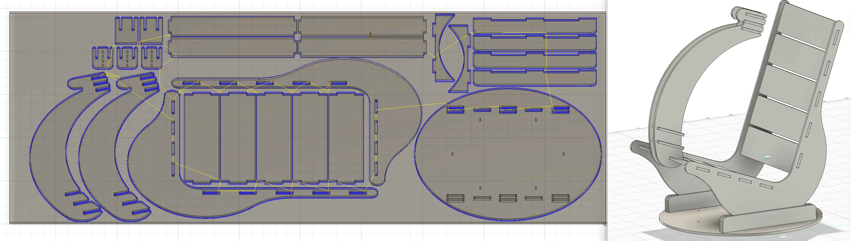
Although I’m more confident in the CAD with SolidWorks, because we were taught to do CAM later on the Fusion, I decided to also do the CAD for my chair originally in Fusion. It took me the whole day to design it, which also used the parametric design for the thickness of the board and the length of joints. I also tried to assemble it at the end in Fusion, and it looks pretty good:
2) CAM to generate G-Code:
Before I came to the CBA machine shop, I simply learnt how to set the parameters for CAM on Fusion:
(https://gitlab.cba.mit.edu/classes/863.25/site/-/blob/main/doc/CAM/readme.md)
Some key information from the recitation:
- The diameter of the end mill is 6.35 mm, set it as a Flat end mill
- Add dogbones for the inner corner with the tool called Nifty Dogbones: Nifty Dogbonesfor Fusion 360 - Ekins Solutions, LLC
- Select the raw wooden board 3d model as “stock”
- Use 2D contour mode and multiple depths
And when I came to CAB on Monday morning, Dan taught me more about the additional parameters for CAM:
Feed and Speed: Spindle Speed = 12000 rpm and cutting feedrate = 220 inch/mm
Height setting (all based on stock top): Retract Height = +2in; Retract height = +5in; Feed height = +0.2 inch from top height; bottom height = -0.45 inch (while the board thickness is around 0.433 inch)
Tabs: Triangular shape; width = 0.25inch and height = 0.3 inch. For the tabs’ position, I have a more detailed discussion later.
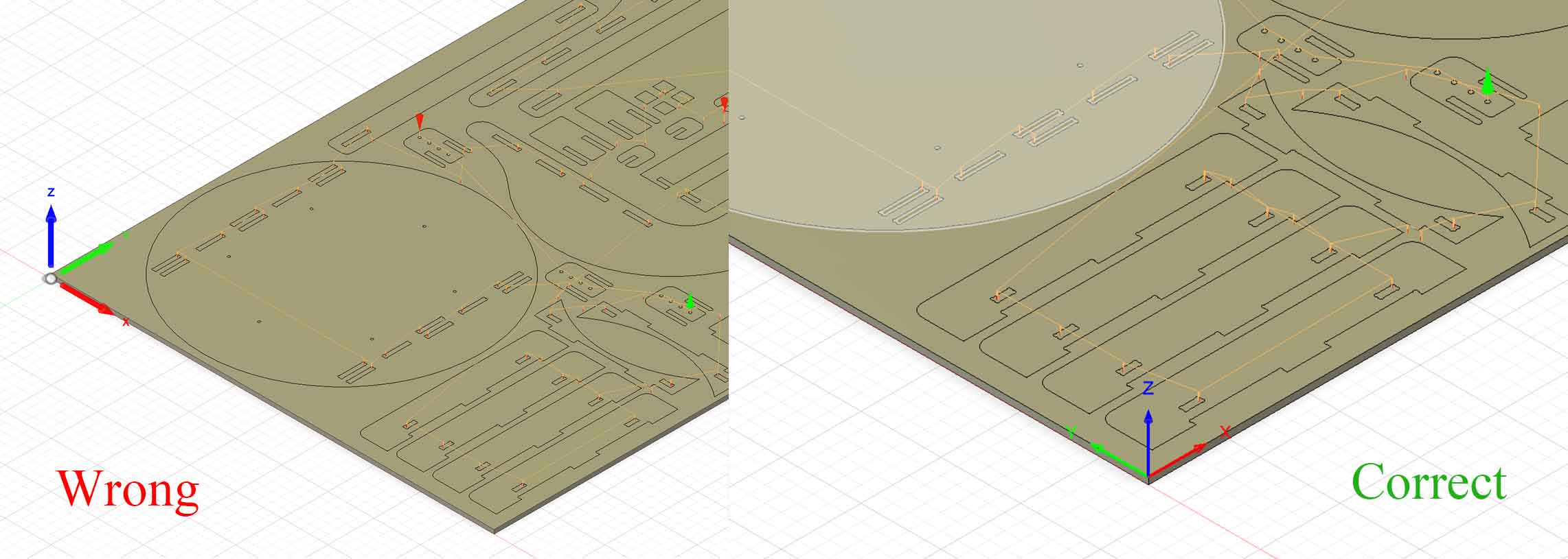
The coordination: zero (0,0,0) is located at the surface-bottom-right point of the board! I made a mistake on this, and I will discuss it later.
3) Debugging for the CAM parameters and the errors I made
After Dan set these for me, it’s very strange that the Fusion keeps warning and can’t post the process/ simulate. I can simulate it a day before, so there must be some parameters that Dan changed that caused the bug.
...

      **Error**: Invalid toolpath point detected '(-nan(ind), -nan(ind), -inf)' for 'onLinear'.

      ^^^^^^^^^^^^^^^^^^^^^^^^^^^^^^^^^^^^^^^^^^^^^^^^^^^^^^^^^^^^^^^^^^^^^^^^^^^^^^^^^^^^^

      **Error**: Failed to execute configuration.

      Stop time: Monday, October 20, 2025 1:16:08 PM
To debug it, I went back to my former version and manually excluded different settings. It took me an hour of reserved machine time to fix this software issue, and the bug was finally located for the tabs: If I change the triangular shape to the rectangular shape, it can work! There might be some issue with the toolpath calculation, but I can’t understand.
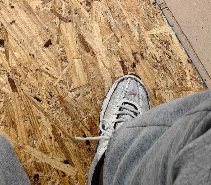
When I tried to load the board into the machine, I noticed the board is not totally flat, and it bulges in the middle. To fix this issue, I stood on the board, added four extra screws in the middle to fix it:
However, I was too early to be glad about the fixing of the bug. Because I manually re-entered all parameters without Dan’s help, I ignored an important setting: the Zero point of coordination! The CNC machine gave me the wrong first point, and it gradually moved out of the board. This is because I set the reversed X/Y coordination!
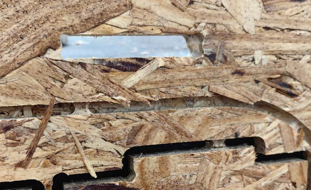
All these issues took me nearly 1.5 hours to fix, so I only had half an hour left and got very limited parts being cut. But I learnt a lot on the first day and also found some issues with the parts I got: In the joints, there is still some material left at the dogbone, and I also found it in the simulation. After trying the different setups, I found the issue came from tags.
The solution for it is shown in the figure below. Basically, we need the positioning method to be “segment” but not “contour”, otherwise it will always consider the joints’ inner contour as the contour that requires the tab, and finally leave some materials at the beginning and end points. I also set the tab distance to be bigger(10 inch), which can save me time for post-processing of big parts, but then small parts need to have tabs added manually because their perimeter might be smaller than 10 inches or only have 1 tab on that. Not sure why, after I changed some additional design, on the second day I can output the process with triangular shape tags again. But it helps: 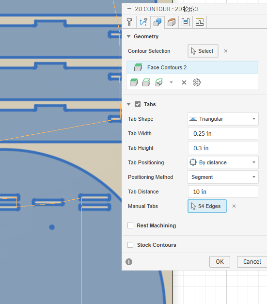
4)Re-cutting and assembly of the chair
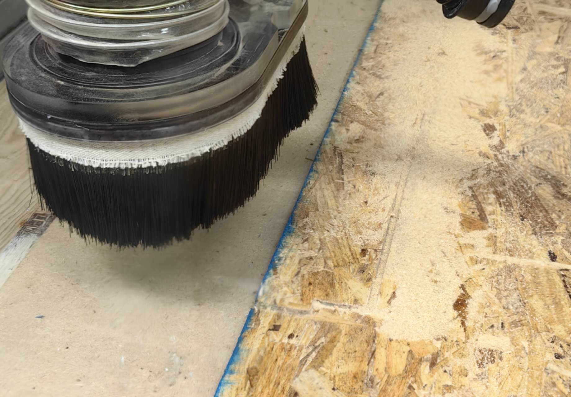
Second day, I came back to the machine with more confidence. It took 2 hours to cut all parts, but it was worth the effort, because the quality is super good. I noticed the most time-consuming part is the Z-axis lift up, which is set as 2 inches (Retract Height), and it’s too high, considering the machine can only move the Z-axis very slowly (plunge feedrate=73.3 inches/min for z axis, only 1/3 of cutting feedrate = 220 inches/min for x and y axis). I assume if I decrease this Retract Height, it can be much faster, especially considering my design has lots of joint holes, which all need several z-lifts during cutting.
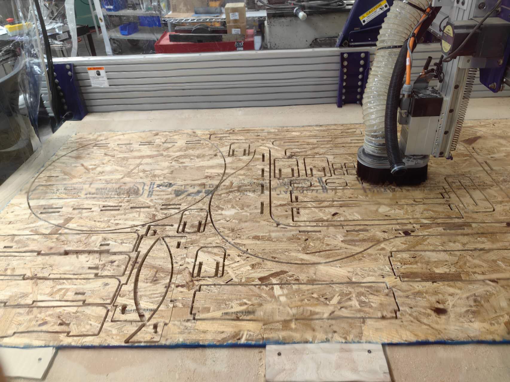
However, you can notice at left-bottom part of the photo, two falcate parts fall off from the weak tabs because I didn’t add enough tabs for them, so the cutting of their joint failed. I also planned to drill some screw holes in the had shape small parts, which can’t be machined with a 2d contour, because the diameter of the holes is just a little bigger than the end mill. As a result, I added the additional bore process in Fusion, but because of some issues, it does not output after the same 2D-contour cutting G-code.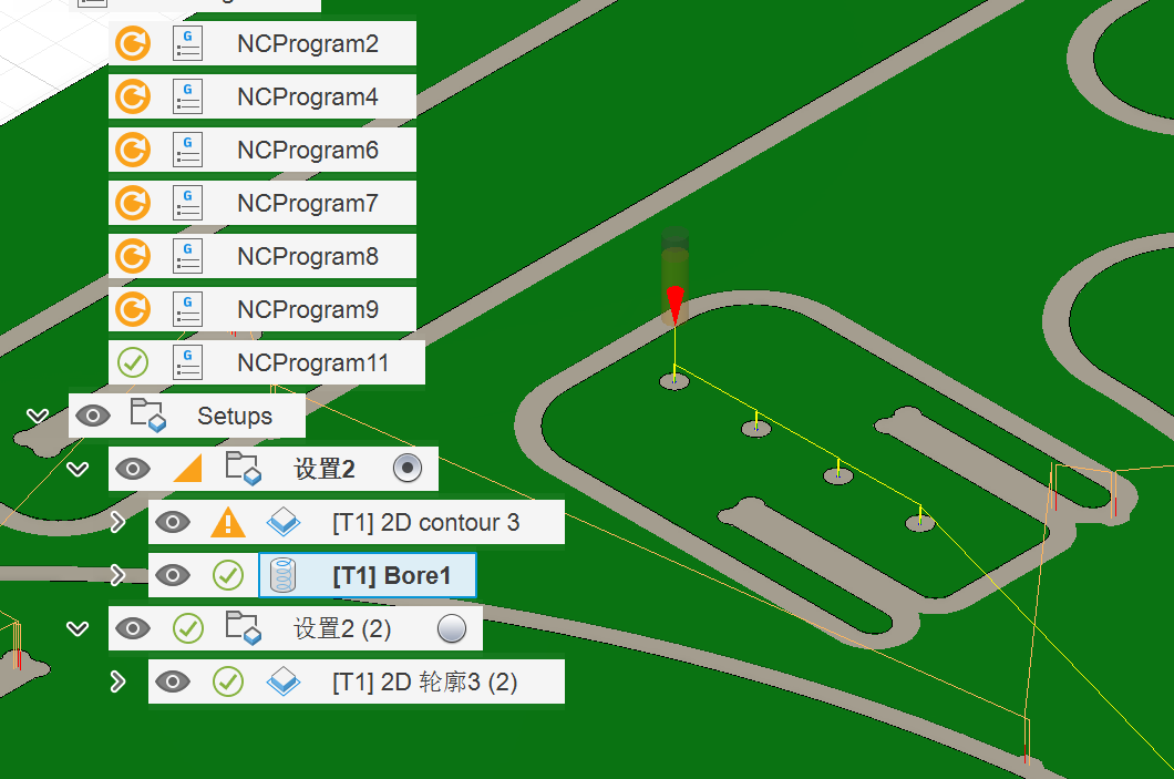
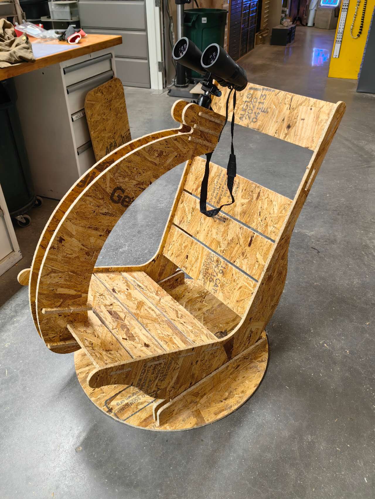
And my chair finally looks like this! My turntable bearing from Amazon is delayed for delivery, so I can’t rotate it on the azimuth axis. But the elevation axis can work smoothly without any metal bearing, which is surprising! I used only one screw to fix my tripod ball head to the chair and connect it to my binoculars, but to be honest, this chair is too hard and not comfortable!
And this wooden material is not strong enough, so the binocular holders will shake. Another issue is that when someone sits on it and lies down, it will be super hard to get up again without anyone else’s help! I will try to fix this issue when I redesign the chair for the electronic version.
The original Fusion design files with CAD and CAM: Download