Introduction
This assignment is targeted at learning how to use EDA (Electronic Design Automation) tools to build PCB boards. Unfortunately, I didn’t attend the lecture this week since I was out for a meeting during whole week. I watched the video for recitation from TA (2025-10-03 11-18-14 on Vimeo) and tried to replicate its example about using Fusion to create an XIAO RP2040 development/test board with LED, bottom, and pin connectors.
1) The problem I encountered:
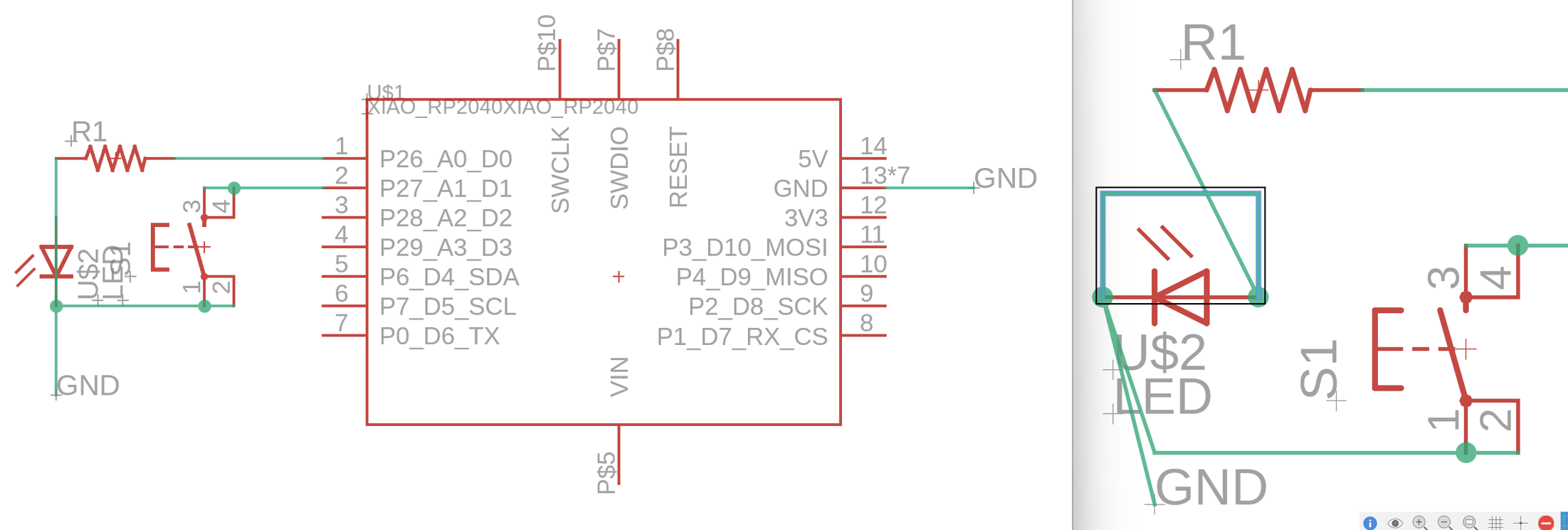
I followed the instructions in the videos, but it didn’t meet my logic when I tried to pour copper with the POLYGON function, because I noticed two pins on my LED were both connected to the GND:
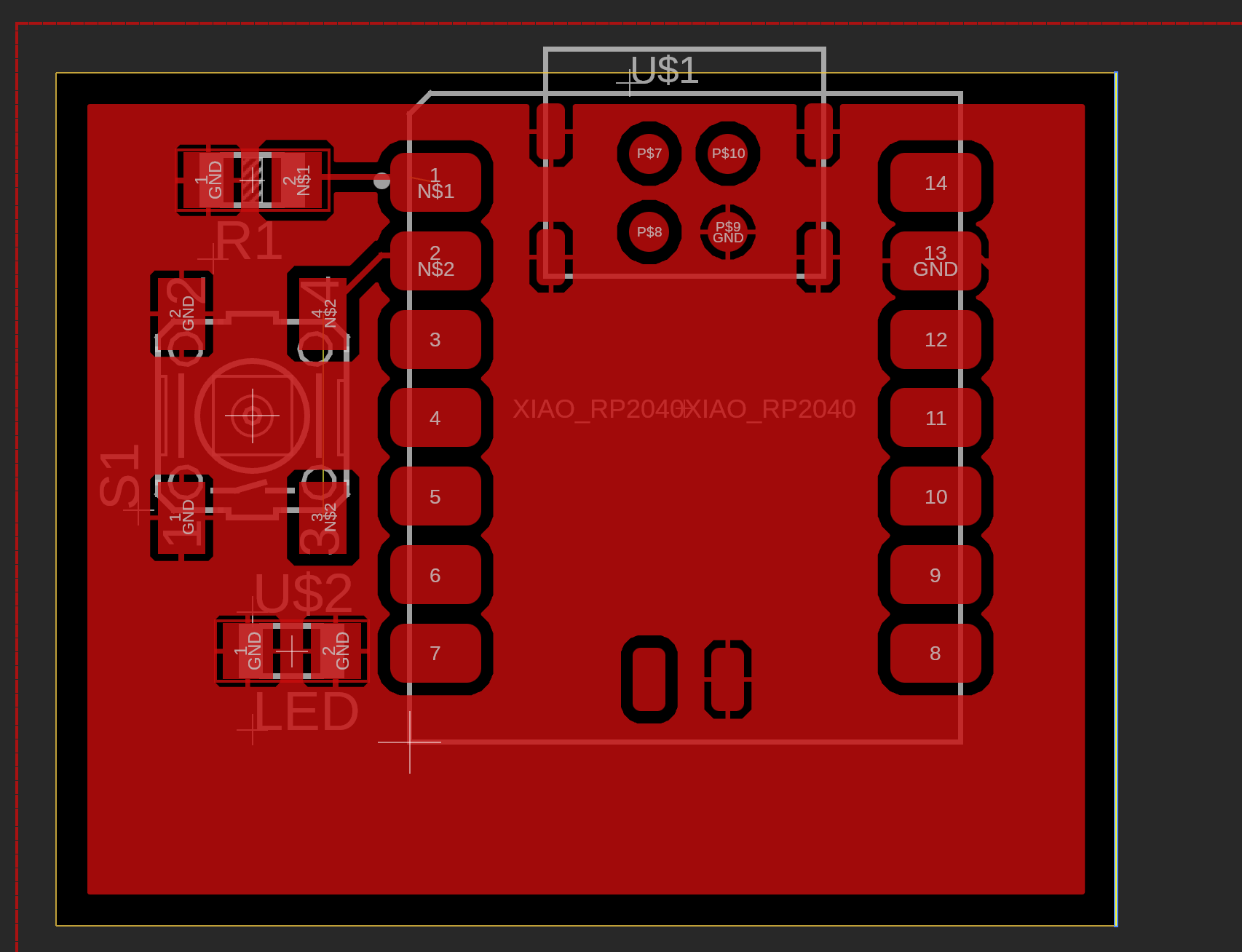
But when I checked my original schematic design, it seemed normal. However, the polygon function connected both pins to GND means there must be some problems in the schematic design that I ignored. Finally, when I tried to rotate that strange LED, I found the problem: I mistakenly shortened the pins of it, but the line was superposed on the LED, so it’s hard to see!
After I fixed it, everything came back to the trail. Finally, I successfully finished the examples in the video but it’s my own version: 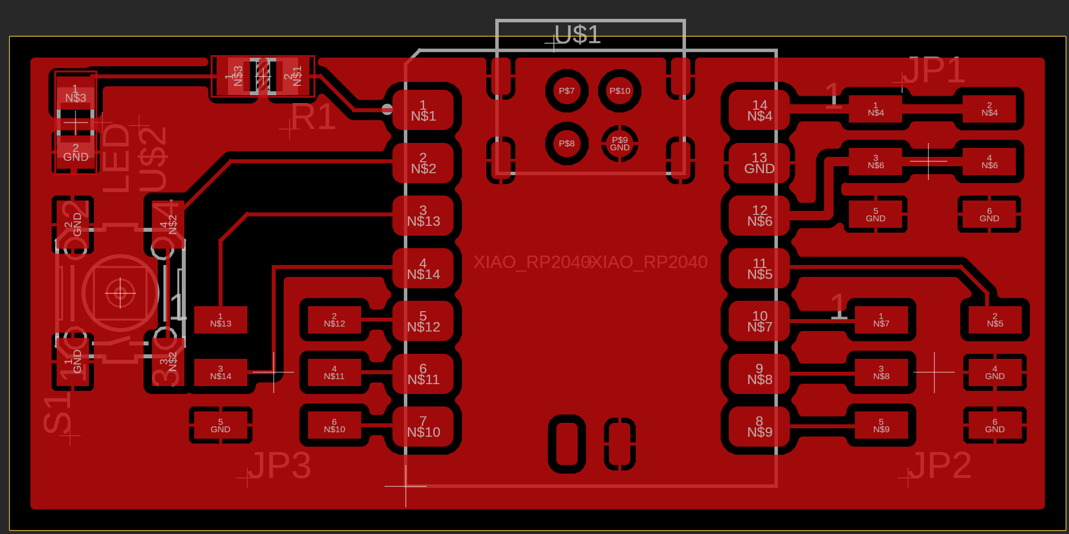
2) The idea to design the uniform PCB controller platform for my spectrometers:
Considering my limited time last week and this week, I didn’t get enough resources to build a customized board since this is my first time trying EDA. However, I do have the ideas on the PCBs that I want to build: A Spectrometer remote control board.
To begin with, I want this board to have the following functions:
- Several stepper motor controllers (2-4) for the electronic focusing and wavelength selection;
- Servo Motor controller, possibly 1-2 of them, for the calibration lid
- Several 12V/5V DC outputs for calibration lamps/LED, which means I need a boost module
- Sensors, like a hall sensor, are used to find the home position of the rotatable grating.
- WIFI function for remote communication without signal cables, to reduce vibrations. This means I should better choose XIAO ESP32-C3
The function of it shouldn’t be very complex, but it needs a lot of I/O ports. XIAO definitely has enough computing resources for it, but maybe not enough I/O ports. So there are two solutions:
- Use MCP23017 (16-bit I/O Expander with I²C Interface) to expand the I/O ports to 16 more (Which seems not to be in the fab class inventory). This is the suggestion from ChatGPT
- Use two or even more XIAOs to communicate and work together
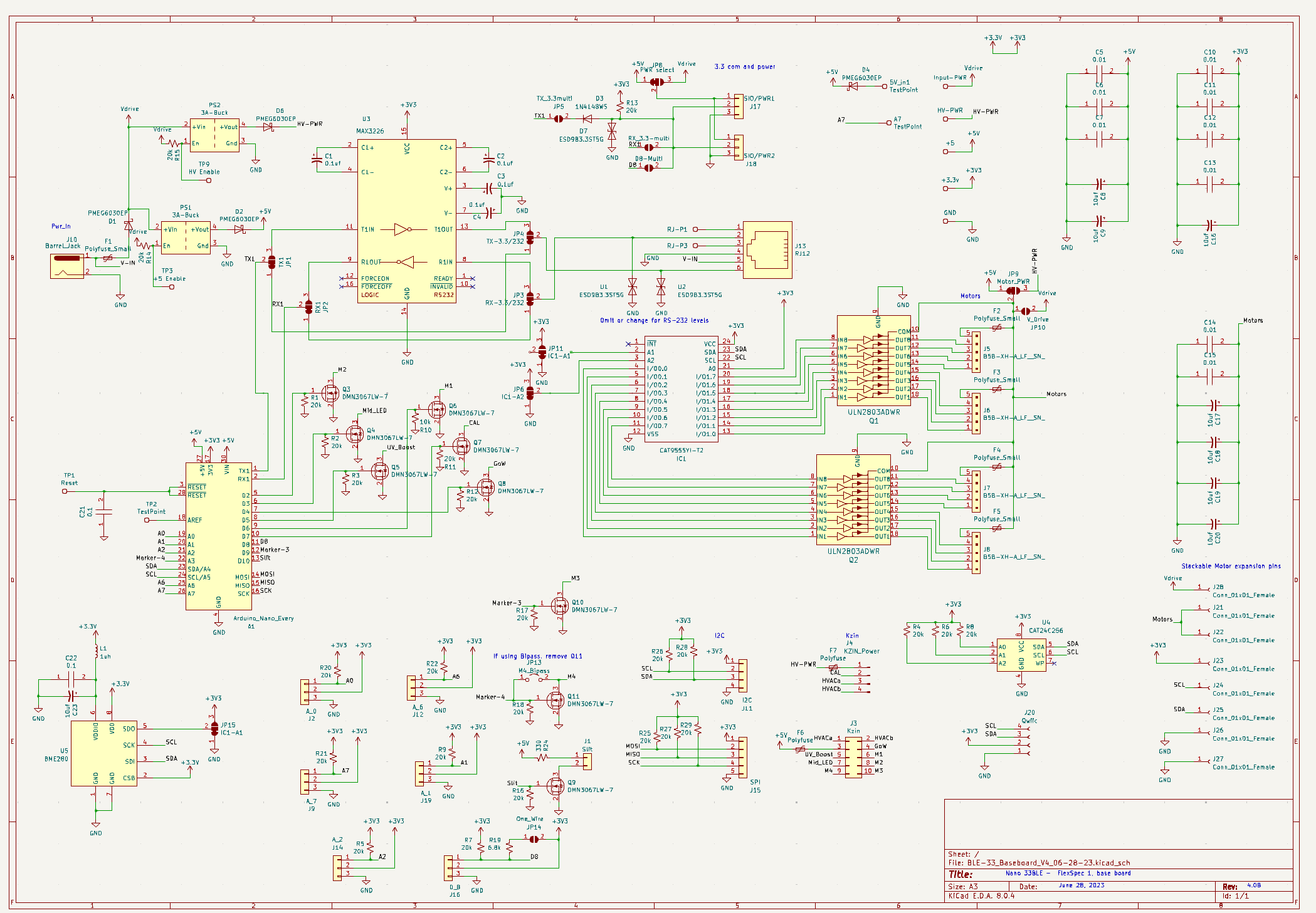
Now I have two open-source programs with similar functions to learn from them, but they are too big:
UVEX 4i: Montage électronique 4.13 – UVEX 4
They are still using the super old “Arduino MEGA 2540” as a microprocessor. I can use more smaller, modern processor like RP 2040 to replace it. Now I have the physical board to learn how it works.
They didn’t publish the files of their design publicly. I personally contacted them, and got the PCB files (KiCAD). I also printed the boards from JLC, but I still haven’t started to solder them. From the original design, I can learn a lot.