Introdcution
The homework of this week is aimed at using sensors to measure something with a microcontroller. I developed a Raspberry Pi Pico W development board during Electronic Production Week, and I can use it with a Dupont thread to communicate with a sensor breakout. However, not all the input devices listed on the online inventory are actually still in stock, so the devices I found in the actual inventory are listed here:
6-axis motion sensor: GY-521 MPU-6050
GPS Module: NEO-6M
Laser TOF distance sensor: adafruit VL53L0CX
Digital Microphone: ICS43434 I2S MEMS Breakout (randomly found in the corner of an unlabeled drawer, not sure whether it can work)
Doppler Radar: RCWL-0516
I will focus on the digital microphone this time, because I want to build a device that can listen to questions during stargazing with a microphone, translate them into text, and then send them to the OpenAI API, receive back the answers from the internet, and then use a speaker to output.
The hierarchy of an embedded system:
MCU development board and MCU
MCU: Micro Controller Unit 微控制器 (e.g.: RP2040, esp32), including CPU/RAM etc inside
MCU development board: (e.g. : Raspberry pi pico W / XIAO RP2040),
with MCU, USB port, 3v3 power regulator chip, wifi module, etc
Hardware interfaces for communication
1)GPIO: General Purpose Input/Output
Multipurpose, can be defined for different functions
2)UART: Universal Asynchronous Receiver/Transmitter (1 to 1)
Serial communication 异步串口通信 (TX/RX, 2 lines), without clock, needs a Baud rate
3)I2C: Inter-Integrated Circuit (Bus Communication, 总线通信, n to n)
(SDA/SCL, 2 lines) slower but multiple devices can be connected to two bus lines
Serial Clock Line (SCL): used to synchronize all devices’ communication rates
Serial Data Line (SDA): used to transfer the data between the master and the slave
Needs pull-up resistors to maintain the high level!
4)SPI: Serial Peripheral Interface (1 to n, fast communication)
Serial Clock (SCK)
MOSI (Master Out Slave in)
MISO (Master In Slave Out)
CSn/CS (Chip Select, used to select different slavessuoy)
5)I2S: Integrated Interchip Sound
BCLK (Bit Clock): The clock reference from the MCU to the microphone
DOUT (Data out): The real sound data output from the microphone to the MCU
LRCLK (Left-Right Clock): Select the Left and right channels (for MCU to identify the channels)
SEL (Channel select): low level means left channel and high level means right channel (for the microphone to define the channels that it’s working on)
The debugging of my old development board
As I mentioned, I plan to use the board I designed two weeks ago, but I didn’t have the proper cable to do this. As a result, I will test the function of it first.
However, I noticed the OLED screen can’t work properly. As a result, I used the multimeter to test the pins on the OLED, and the GND pin was measured as ~3V relative to the GND of the board, which means the GND pin was not connected properly. I added more tins to the cold joint, and the GND pin was measured as normal voltage.
But the screen still can’t work properly. Then I measured the other 3 pins, and noticed the VCC pin was ~1V while the SCL/SDA pins were ~2V. This does not make sense because VCC should reach 3.3V. Okay, it’s a cold joint again, but the trace and cold joints are all under the board, so I can only use the fly wire to fix it. It finally looks like this:
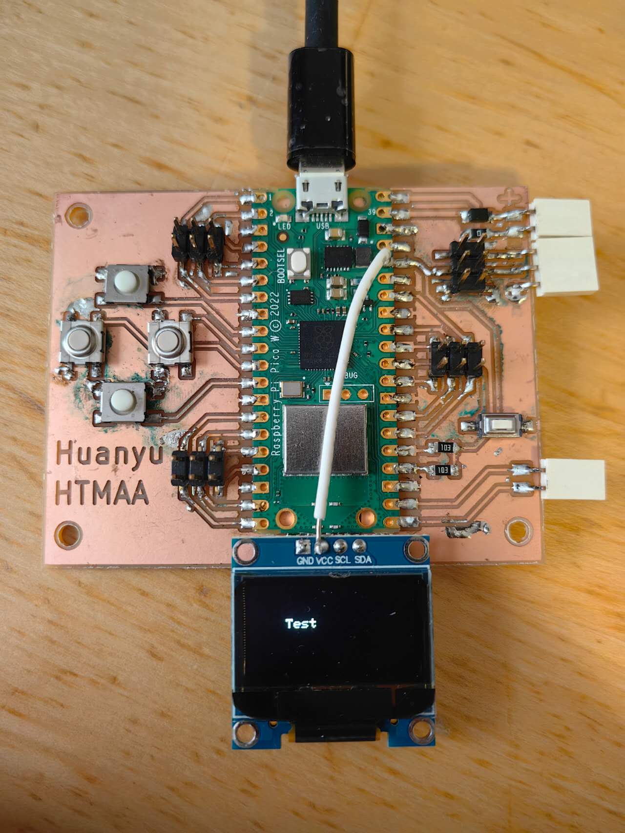
The testing of a digital microphone
From I2S I discussed before, to connect the breakout properly, I need:
Two power pins: 3V3 and GND (white and black lines); Data from microphone: DOUT to GP1 (purple line); BCLK to GP0 (blue line); LRCL to GP2 (while line, not necessary); SRL to GND (choose left channel, not necessary). And look out, this digital microphone has a small hole as a voice input position.

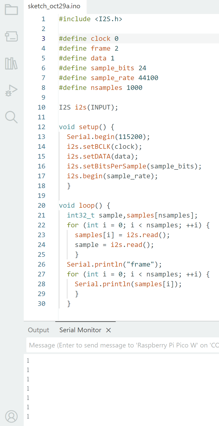
I used the test code from Neil and changed the pin number for the Raspberry Pi Pico W, just randomly chose three GPIO. However, I still can’t get any effective signal back from the microphone, since it always outputs the high-level “1”
I doubt whether the breakout board I randomly found is a broken one, since I tested it with the same setup on another commercial development board and it still can’t work. I plan to use the logic anaylzer or XIAO rp2040 to test it again to figure out where the bug is.
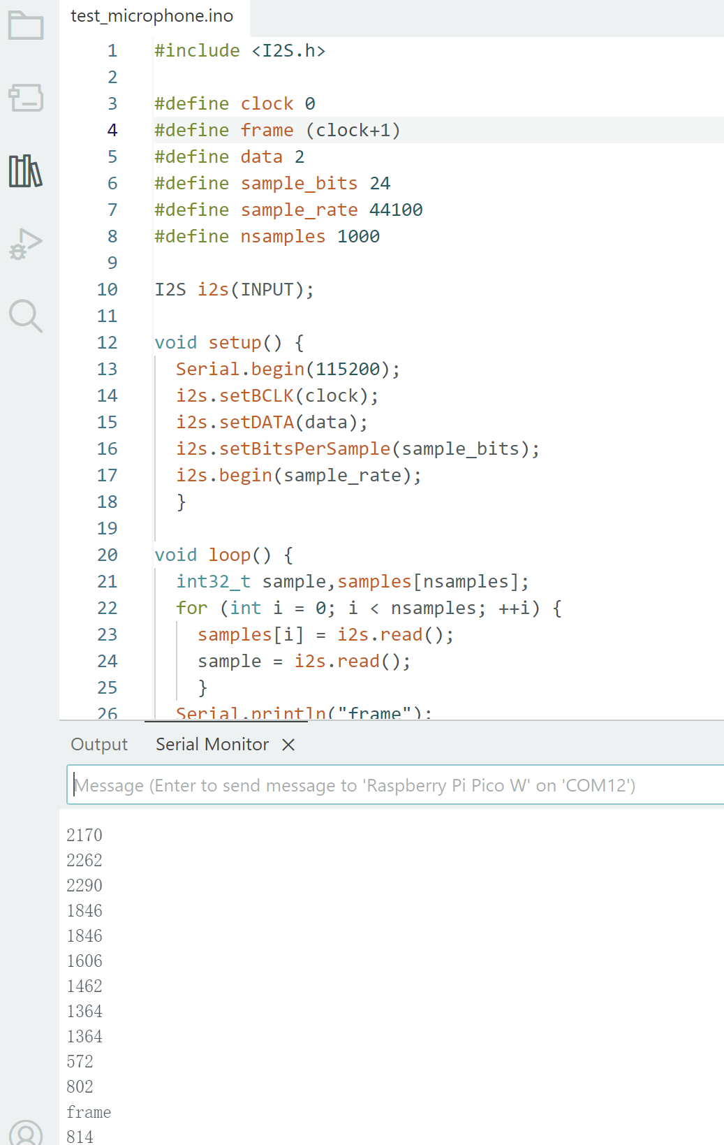
During the lecture of output devices, Edward Chen told me the micorphone library used in example code has a limitation on the pins to be used. The frame(LRCL) must use the GPIO pin number exactly after clock(BCLK). I ignored this setup in example code and I thought the pin sequence will not influence anything, but I was wrong. I fixed the pin sequeence and tried again, then I can receive signal this time:
And Sun Chuanqi shown a similar successful product with microphone on the lecture that day, so I would learn from his documentation. It seems he used a dfferent library which is better.
Sun's work reference