Introduction
This assignment is targeted at
- Use a parametric design to build a CAD model for laser cutting, which can adjust parameters easily
- Learn how to operate a laser cutting machine and understand the parameters involved
- Use the kerf test to find the best parameters
1. Background: Fullerene
Fullerene is a group of special molecules made entirely of carbon, and they form a ball structure with the combination of pentagons and hexagons, leading to their uniform geometric structures.
The most classic fullerene is C60, which is also called “Buckminsterfullerene” because the architect Buckminster Fuller proposed a lot of similar structure buildings. In chemistry, especially for astrochemistry, there’s a funny fact that C60 and C70 are the only identified interstellar molecules in IR absorption lines (DIBs, the diffuse interstellar bands). And recently, my group also detected some interstellar Polycyclic Aromatic Hydrocarbons, which are the smaller pieces of fullerenes, that can be helpful to understand how interstellar fullerenes form. With several fullerene models, we can better examine which sub-structure PAH to search next.
This is not the first time a laser-cutting buckyball has been proposed for the HTMAA class. For example: Fab Academy 2018 - Jun Kawahara; Yogi Kulkarni - Fab Academy 2016; However, they are all focusing on the faces out of structural consideration. Here, I want to build it based on the viewpoint of chemistry, which pays more attention to nodes and bonds.
I noticed a YouTube video about laser cutting C60: Laser Cutting Fullerene C60 / AEON LASER / NOVA16 Super / 3D CAD / SolidWorks. It seems ideal for me, so I tried to replicate it with parametric design, and even extend it to other fullerenes like C20 and C70.
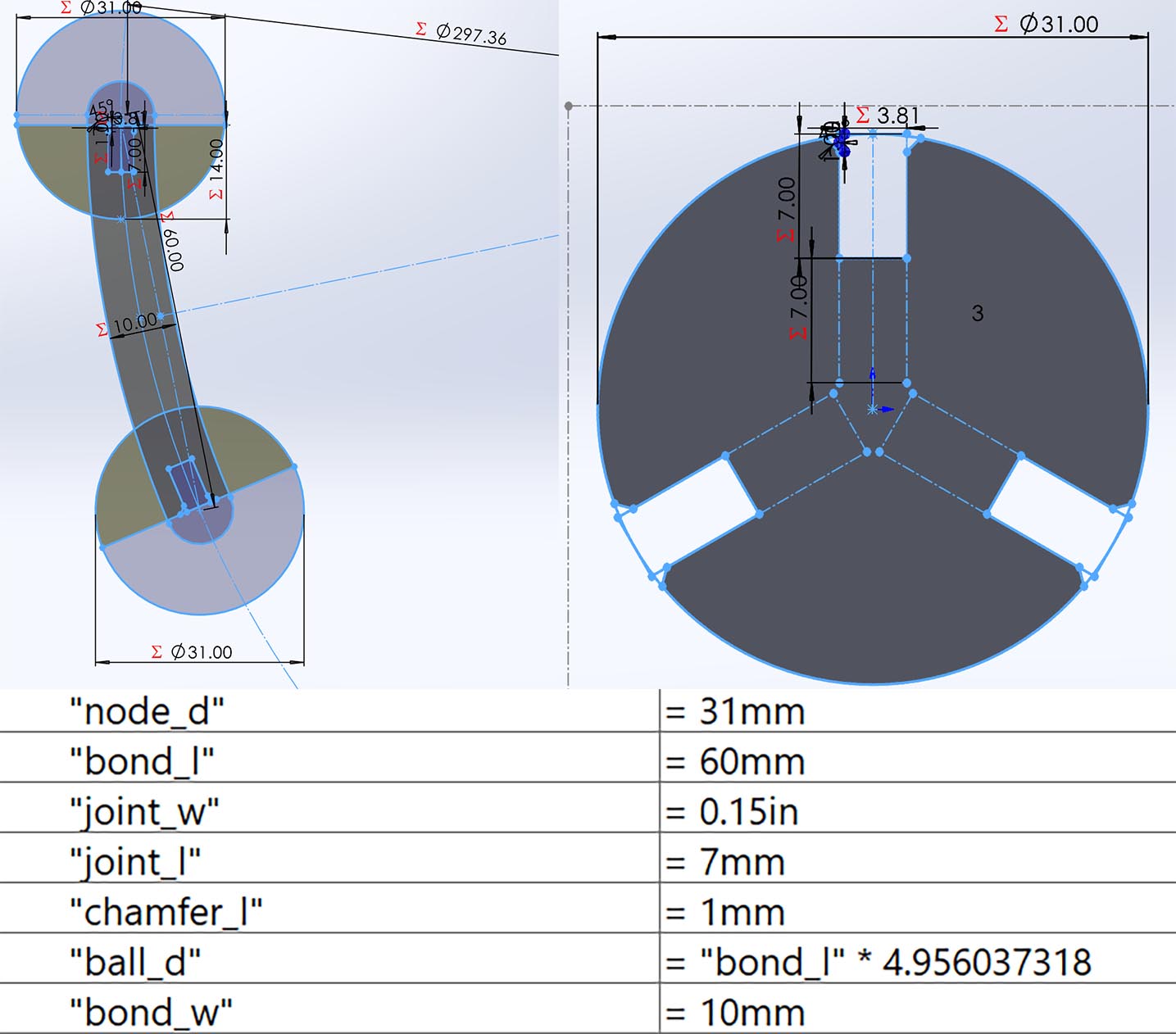
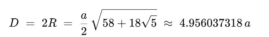
I built this parametric model in SolidWorks and set these parameters, including the length for bonds and diameters for nodes, the depth of chamfer, and the joint shape. The final buckyball circumcircle diameter is calculated based on this formula from geometry:
2. Kerf test and laser cutting parameters:
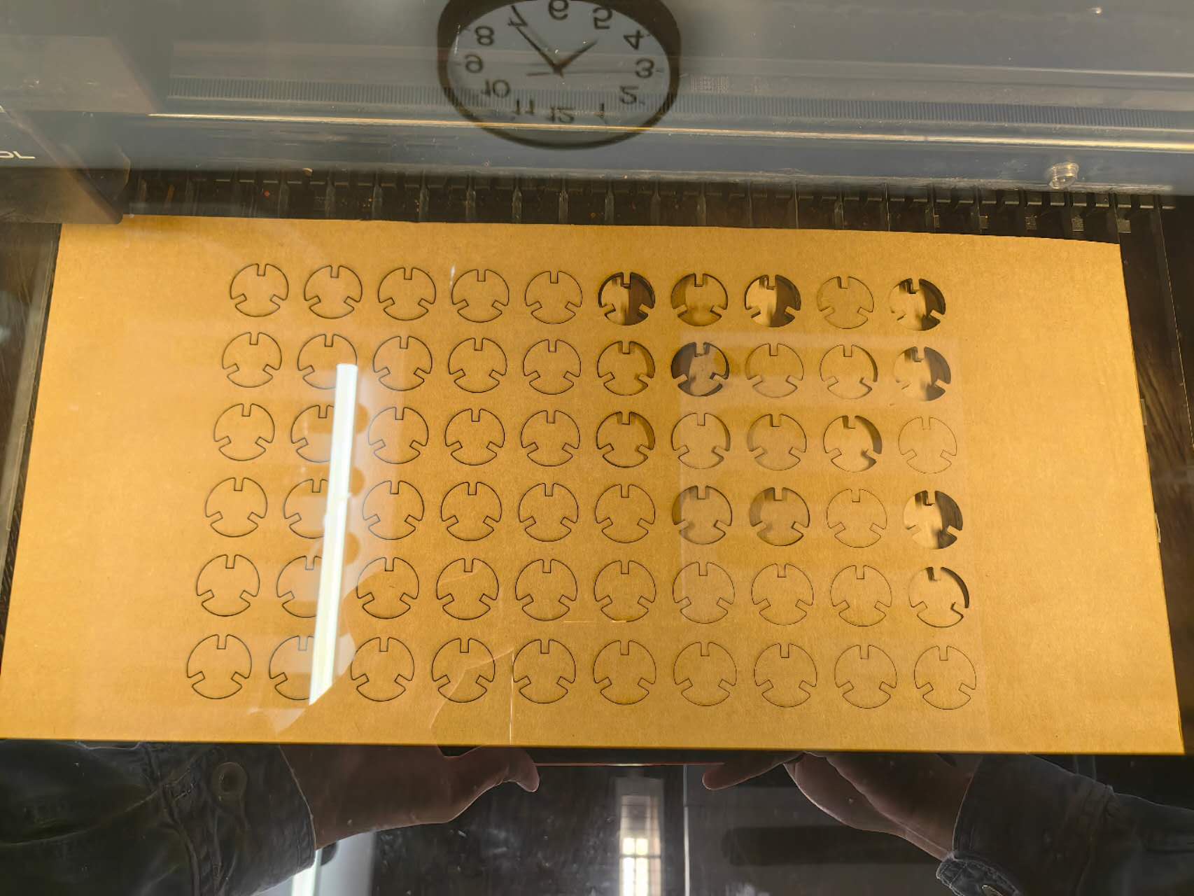
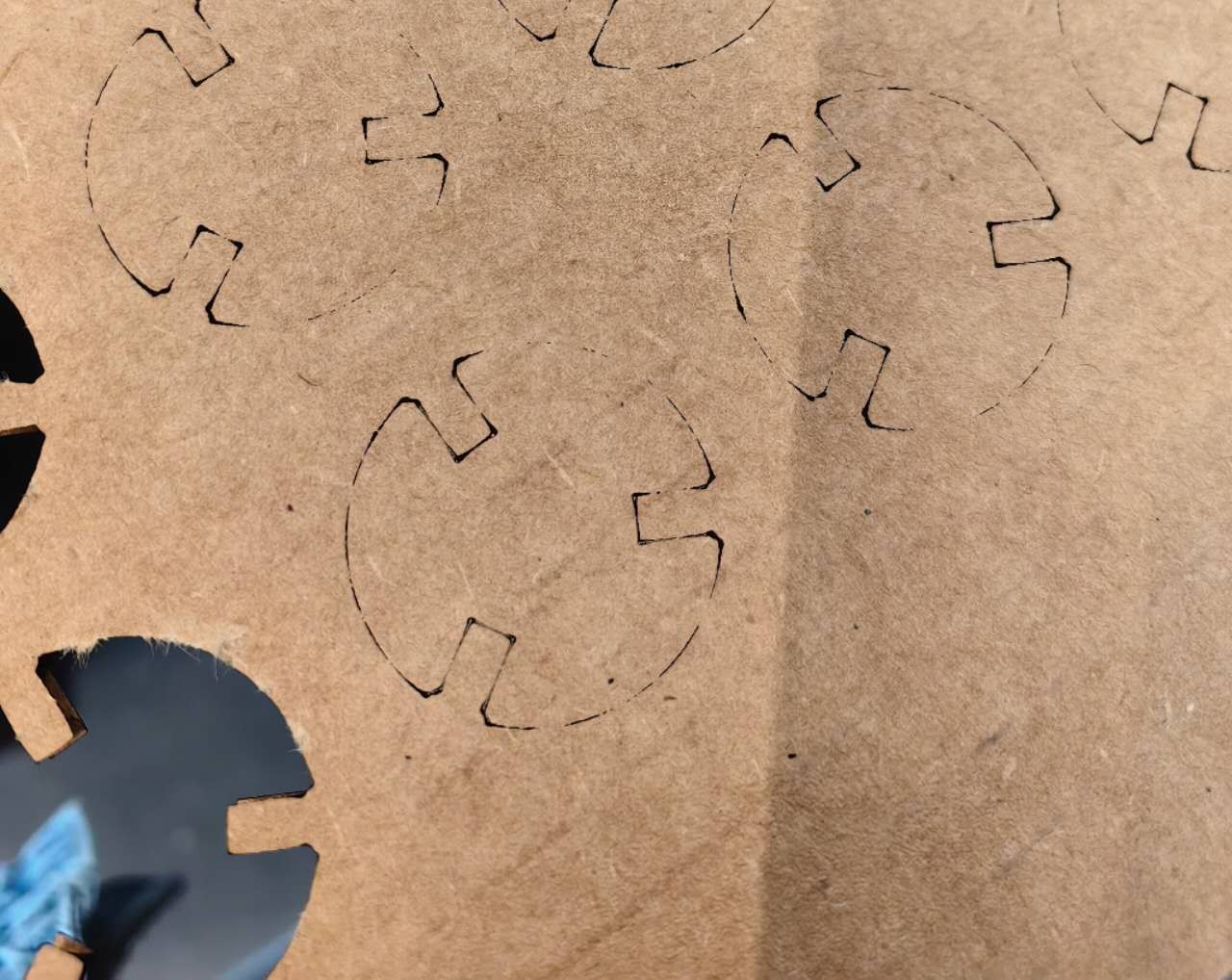
The width of the joint is set as the thickness of the cardboard, but I need to do a kerf test to figure out whether I need to change this parameter to better assemble bonds and nodes:
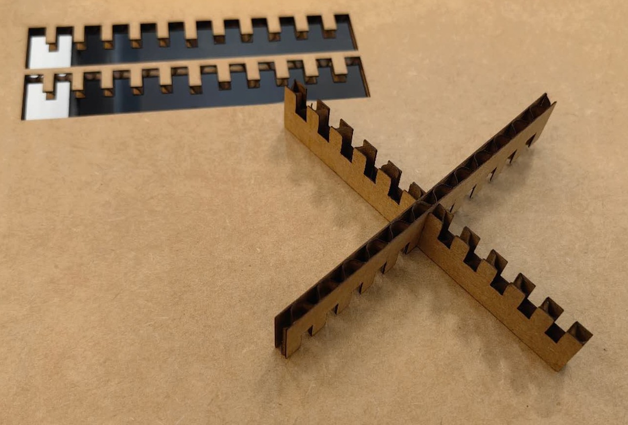
At the center of this test part is a 0.15-inch joint without any kerf; on the left side, each joint has -0.1mm kerf step; and on the right side, each joint has +0.1mm kerf step. The first laser cutting test was set with parameters from Ceci, who documented this in our section earlier: 87% power and 37mm/s speed. (XTOOL P2) It worked pretty well, and you can see even without any kerf, the joints can be tightly combined. I found -0.1mm can also work, but it really can’t work for -0.2mm. As a result, I decided to use zero kerf next, which means I didn’t need to change parameters.
(The Dxf file for 4 bonds of C60)
(The Dxf file for 2 nodes of C60)
3. Problems and solutions:
When I extended this setup to a bigger board (12 inch*23 inch), some problems happened:
 You can see that, when compared with the right side, on the left side, the cutting lines are thicker, and it’s not fully cut through the board. This problem is caused by the bending of the big board, because it’s not flat enough. To avoid the moving laser head hitting the board, I set the focus of the laser to the right side, the highest point, but the left side missed the focus, which caused a wider kerf and lower power per unit area. So, in all later cuttings, I slowed down the speed to 30 mm/s
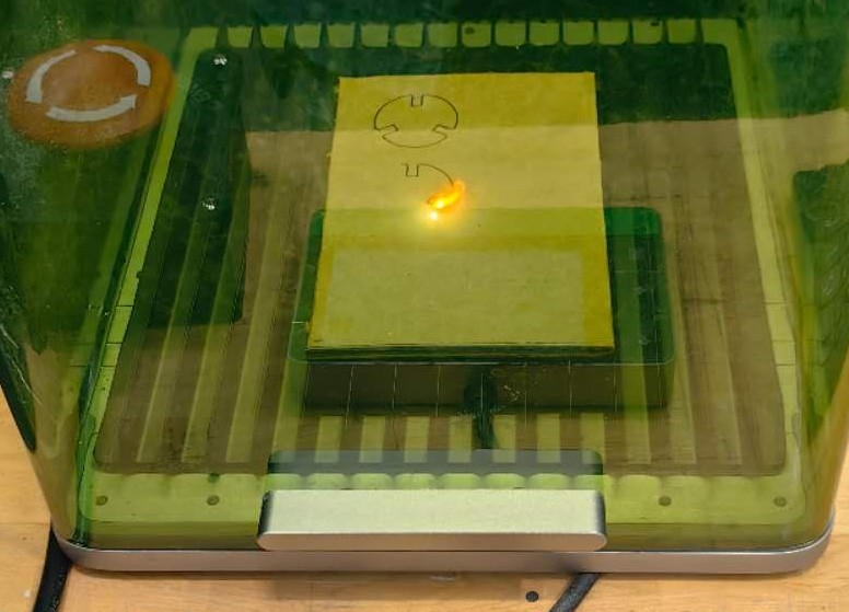
I also tried another smaller laser cutting machine, XTOOL F1 Ultra, because the bigger machine is too busy to wait. The parameters required to fully cut through our paperboard are: Blue Light laser, 100% power, 20mm/s speed. But look out for the fire! When it’s working at these parameters, a temporary flame emerges and disappears. A safer setup is 25 mm/s or 30 mm/s, but it can’t fully cut the board.
4. Assembly
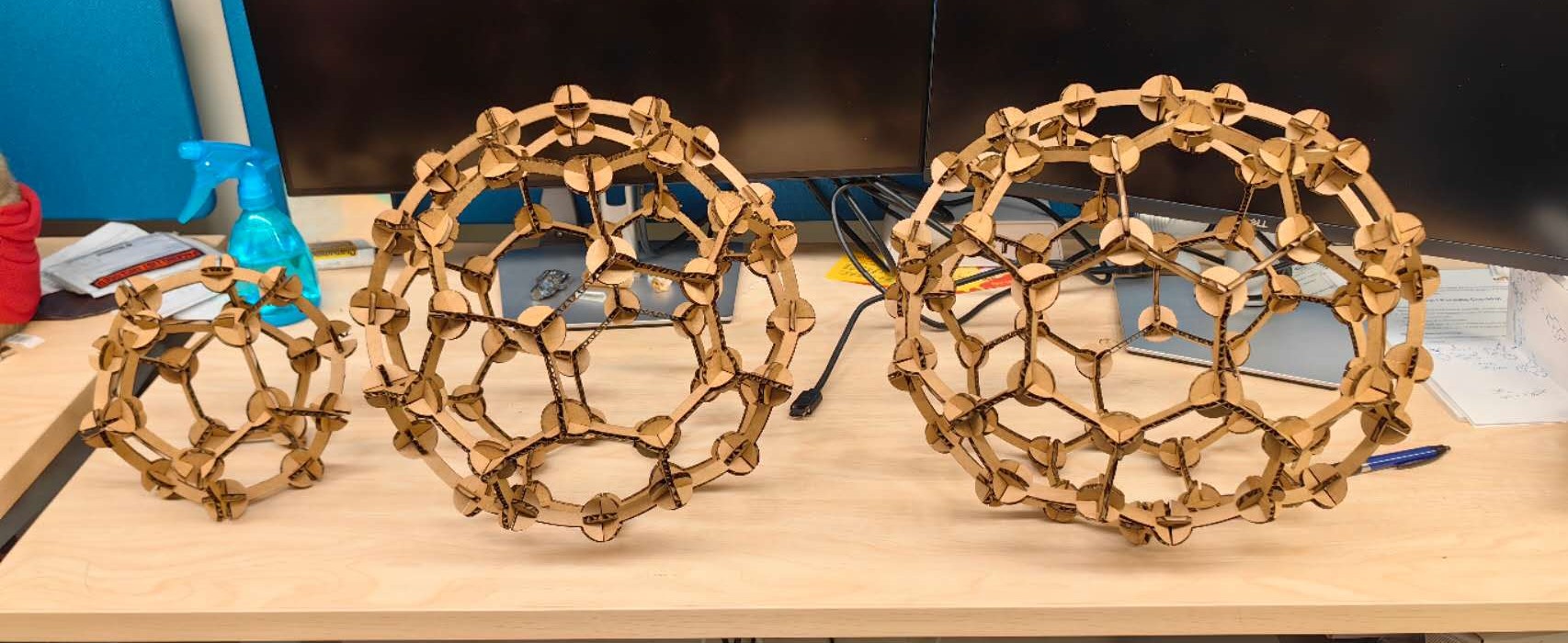
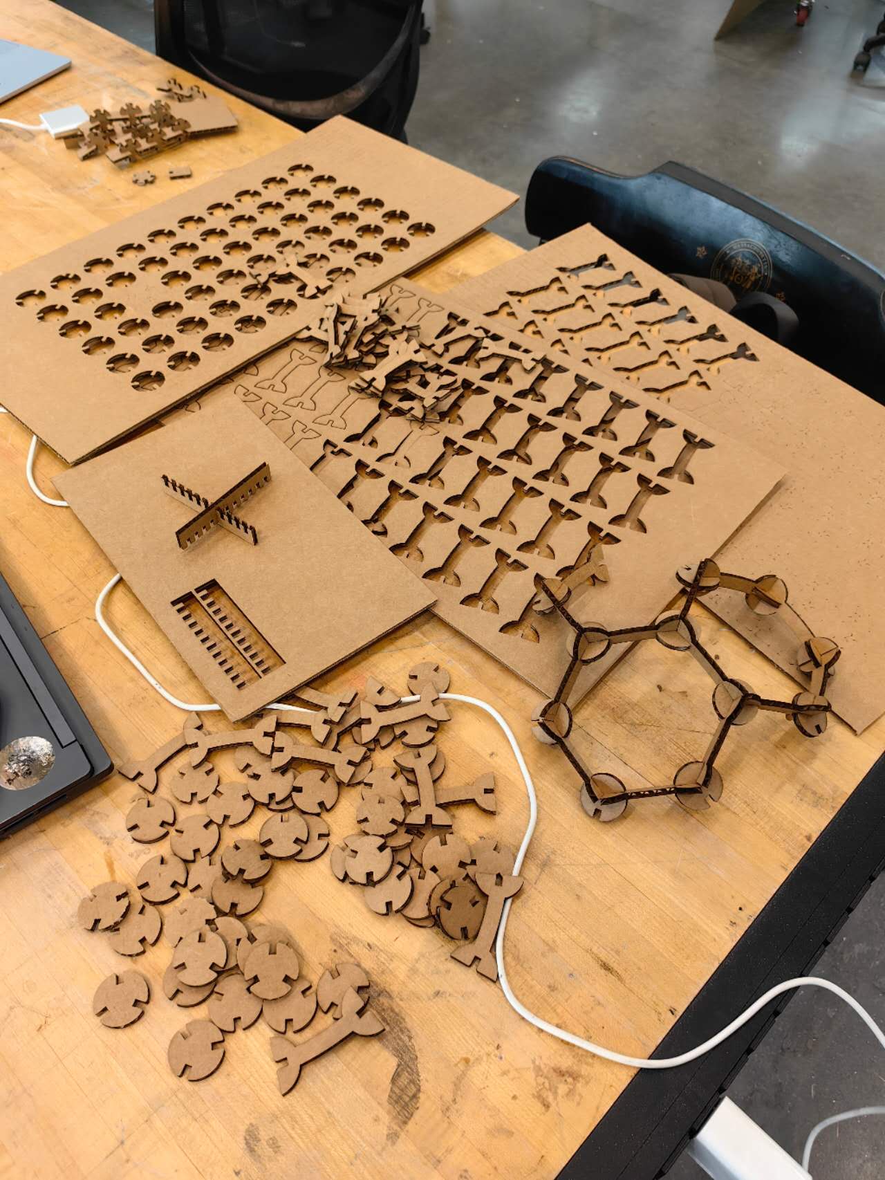
Then I got my bonds and nodes, and I began to assemble C60:
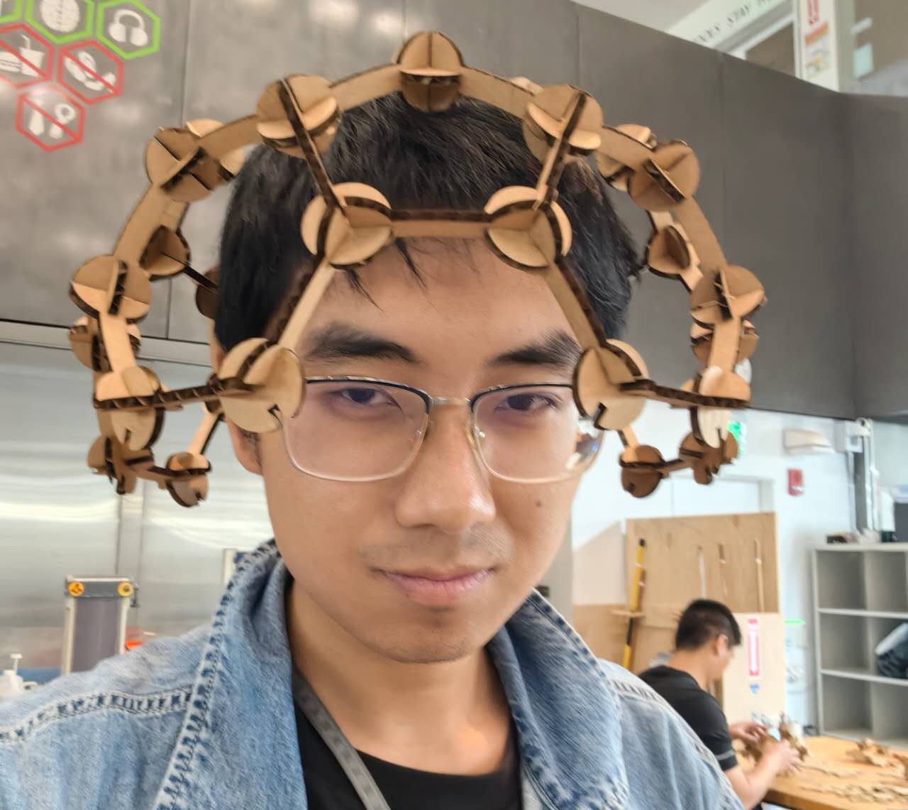
 I started from the pentagon and circled it with five hexagons, which formed a bowl structure called Corannulene; Or I can also start from another double hexagon and double pentagon structure, which is called pyracylene. These two patterns repeat and will finally form the buckyball. In the middle, I can even use it as my hat:
When it’s close to being finished, I figured out I made another mistake: I lost two nodes and I only cut exactly 60 of them without redundancy… which cost me much more time to wait for others to finish their cutting. Learnt something from these experiences!
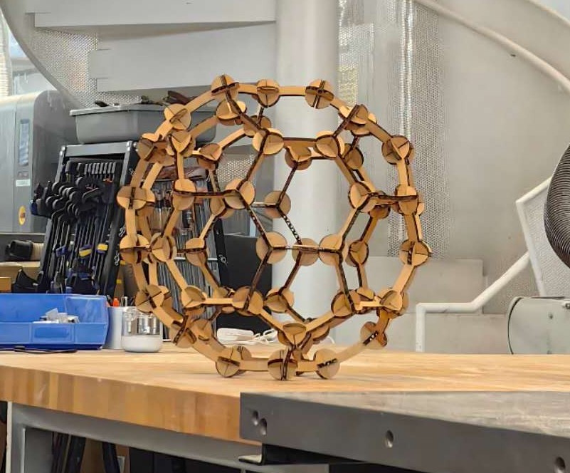
Second day, I cut more bonds and nodes, and I finally got both C20, C60, and C70! For C20, it’s a little distorted since I used the circumcircle diameter for C60. Luckily, this is cardboard, so it can change shape a little.